3D R Solo Manuale di installazione

Operation Manual

3DR Support
We’re here to help! If you have any questions about your Solo
or if you need technical support, don’t hesitate to contact us.
online: 3dr.com/support
email: [email protected]
call: +1 (858) 225-1414 (direct)
+1 (855) 982-2898 (toll free in the US and Canada)
Support line hours:
Mon-Fri 8 am to 5 pm PST
Sat 9 am to 3 pm PST
3D Robotics (3DR)
1608 4th Street, Suite 410
Berkeley, CA 94710
Tel. +1 (858) 225-1414
3dr.com
Solo Operation Manual vA
DCT0077
© 2015 3D Robotics Inc.
GoPro, HERO, the GoPro logo, and the GoPro “Be a HERO” logo are
trademarks or registered trademarks of GoPro, Inc.

Contents
1 System Description 1
1.1 System Overview 1
1.2 Aircraft Overview 2
1.3 Controller Overview 3
1.4 Operating Parameters 5
1.5 Autopilot 5
1.6 Propulsion 6
1.7 Electrical System 7
1.8 Communication 8
2 Setup 9
2.1 In the Box 9
2.2 Battery 9
2.3 Controller 11
2.4 Propellers 12
2.5 Camera 13
2.6 App 14
3 Safety 16
3.1 Location 16
3.2 Environmental Awareness 16
3.3 Propellers 16
3.4 Home Position 16
3.5 Altitude & Safety Fence 17
3.6 Emergency Procedures 17
3.7 Power Management 17
3.8 Flight Battery 18
3.9 Controller 18
3.10 GPS Management 19
3.11 Signal Management 20
4 Operating Procedures 21
4.1 Preflight Checklist 21
4.2 Takeoff 21
4.3 Land 22
4.4 In-Flight Data 23
4.5 Joystick Control 24
4.6 Smart Shots 27
5 Maintenance 28
5.1 Legs 28
5.2 Motors 29
5.3 Pairing 31
6 Appendix 32
6.1 Specifications and Operating Parameters 32
6.2 Warranty 33
6.3 Regulatory Compliance 33
6.4 Sensor Data Sheets 34

Figures
Figure 1.1.1: Solo System Context Diagram 1
Figure 1.2.1: Solo Exterior Overview 2
Figure 1.2.2: Solo Interior Overview 3
Figure 1.3.1: Controller Schematic Diagram 4
Figure 1.4.1: Solo Operating Parameters & Specifications Table 5
Figure 1.5.1: Solo Onboard Sensors Table 6
Figure 1.6.1: Motor Schematic Diagram 6
Figure 1.6.2: Solo Motor Order 7
Figure 1.7.1: Solo Electrical System 7
Figure 2.1.1: Solo Parts 9
Figure 2.2.1: Charge Solo Battery 10
Figure 2.2.2: Insert Solo Battery 10
Figure 2.3.1: Charge Controller 11
Figure 2.3.2: Power On Controller 11
Figure 2.4.1: Attach Propellers 12
Figure 2.5.1: Attach Camera 13
Figure 2.5.2: Camera Configuration Process 13
Figure 2.6.1: Connect to Solo Link 14
Figure 2.6.2: Controller Preflight Update Prompt 14
Figure 2.6.3: Solo App Update Process 14
Figure 2.6.4: Controller Updating Display 15
Figure 2.6.5: Controller Update Display 15
Figure 2.6.6: Solo Update Displays 15
Figure 2.6.7: Viewing Video on the App 15
Figure 3.5.1: Controller Maximum Altitude Warning 17
Figure 3.7.1: Low controller battery warning and return-home notifications 18
Figure 3.7.2: Low flight battery warning and auto-land notifications 18
Figure 3.10.1: Controller Waiting-for-GPS Prompt 19
Figure 3.10.2: Controller GPS Lost Notification 19
Figure 3.11.1: Controller Signal Lost Warnings With GPS 20
Figure 3.11.2: Controller Signal Lost Warnings Without GPS 20
Figure 4.2.1: Controller Start Motors Prompt 21
Figure 4.2.2: Controller Auto-Takeoff Prompt 22
Figure 4.3.1: Return Home Behavior 22
Figure 4.4.1: Controller In-Flight Data Display 23
Figure 4.5.1: Controller Left Joystick 24
Figure 4.5.2: Throttle Joystick Behaviors 24
Figure 4.5.3: Yaw Joystick Behavior 25
Figure 4.5.4: Controller Right Joystick Controls 25
Figure 4.5.5: Pitch Joystick Controls 26
Figure 4.5.6: Roll Joystick Controls 26
Figure 5.1.1: Leg Replacement Process 1 28
Figure 5.1.2: Leg Replacement Process 2 28
Figure 5.1.3: Leg Replacement Process 3 29
Figure 5.2.1: Motor Pod Replacement Process 1 29
Figure 5.2.2: Motor Pod Replacement Process 2 30
Figure 5.2.3: Motor Pod Replacement Process 3 30
Figure 5.2.4: Motor Pod Replacement Process 4 30
Figure 5.2.5: Motor Pod Replacement Process 5 31
Figure 5.3.1: Solo Pair Button 31
Figure 5.3.2: Controller Pairing Process 31

1
1 System Description
Solo is a reliable, easy-to-use quadcopter optimized for capturing aerial video and still imagery. This section
provides a technical description for the 3DR Solo system, including components, communication, control, telemetry,
and operator interaction.
1.1 System Overview
The 3DR Solo system includes the Solo quadcopter, Solo controller, “3DR Solo” app, and the human operator.
The operator interacts with the controller and app on the ground, and the controller communicates with the Solo
quadcopter during flight.
The 3DR Solo system includes the Solo quadcopter, controller, “3DR Solo” app, and the human operator. The
operator interacts with the controller and app on the ground, and the controller communicates with the Solo
quadcopter during flight.
Solo Quadcopter
Solo is a small unmanned aerial vehicle powered by four brushless motors and four propellers. Solo’s onboard
computers control navigation, attitude, and communications in flight while sending real-time telemetry and video
output and receiving control inputs over the 3DR Link secure WiFi network. Solo is optimized for aerial imagery
using a GoPro® HERO camera.
Controller
The controller provides joystick, button, and dial controls and displays in-flight data on a full-color screen. Using
twin long-range dipole antennae, the controller acts as the central hub for all communication on the 3DR Link
network, receiving all communications from Solo and the app, forwarding telemetry outputs to the app, and
controlling the transmission of all control inputs to Solo.
App
The “3DR Solo” app outputs a live video stream from Solo’s onboard camera to an Android or iOS device. The
operator can use the app to view the live video with overlaid telemetry and access a simplified graphic interface for
controlling Solo’s advanced functions. The app connects to the 3DR Link network to receive video and telemetry
outputs and send control inputs.
Figure 1.1.1: Solo System Context Diagram
Video output
Telemetry output
Control input
Operator
3DR Solo
Controller
3DR Solo
3DR Solo
App
AirGround
3DR Link
Secure WiFi
Network

2
1.2 Aircraft Overview
Smart Battery
The battery connects to Solo’s battery bay. Solo’s power button is located on the battery; Solo can only be powered
when the battery is connected.
Motors and Propellers
Solo’s arms are labelled one through four on the ends of the arms. Motors on arms #1 and #2 spin counterclockwise
and use clockwise-tightening propellers with silver tops. Conversely, motors on arms #3 and #4 spin clockwise and
use clockwise-tightening propellers with black tops.
Orientation LEDs
Each arm contains an LED for ground-to-air directional awareness; the two front arms (#1 and #3) display white, and
the two rear arms (#2 and #4) annunciate red. This LED scheme mimics the headlight and taillight style of a car for
easy association by any operator.
Fixed Camera Mount and HDMI Cable
Solo includes a GoPro® The Frame fixed mount to mount a GoPro® HERO camera. The HDMI cable connects to
the GoPro® to output video and charge the camera during flight.
Figure 1.2.1: Solo Exterior Overview
Solo Mainboard
The Solo mainboard connects all components onboard Solo. It acts as a voltage regulator and power distribution
system for the vehicle, sending power to all components and receiving voltage and current monitoring information
from the Solo Smart Battery.
3DR Pixhawk 2
The Pixhawk autopilot handles all attitude estimation, inertial navigation, and failsafe monitoring for Solo. It receives
data from internal sensors, the external GPS module, the external compass module, and 3DR Solo Link to calculate
Solo’s in-flight dynamics. Pixhawk outputs telemetry data to the 3DR Link network and send control commands to
Solo’s four electronic speed controllers. Pixhawk sends and receives all signal through the mainboard.
Silver-top propeller
Power button
Battery
Rear orientation LEDs
Black-top propeller
Motor
Arm numbering
Front orientation LEDs
Fixed camera mount
HDMI cable
Height: 10.2”
Motor-to-motor: 18.1”
Weight (no camera): 3.3 lbs.

3
Compass Module
The compass module is placed in leg #4 to avoid interference from other electronic components. Data from the
compass is sent to Pixhawk through the mainboard for use in attitude estimation.
GPS Module
The GPS module is located in front of the battery in a copper-shielded enclosure to reduce interference. GPS data is
essential for Solo’s automated flight capabilities. The GPS module sends data to Pixhawk through the mainboard.
Electronic Speed Controllers
Solo contains four electronic speed controllers (ESCs) to manage control of each of the four motors. ESCs receive
commands from Pixhawk through the mainboard and regulate the rotation of the motors to achieve the correct flight
speeds.
3DR Solo Link
The 3DR Solo Link module manages communication between Solo and the controller on the 3DR Link secure WiFi
network. 3DR Solo Link receives all control inputs, outputs telemetry, and outputs video signals to communicate
with the ground over the 3DR Link network. 3DR Solo Link also runs software processes regulating advanced
automated functions and data conversion. This module sends and receives data from Pixhawk through the
mainboard.
Antennas
Twin dipole antenna in the legs #1 and #2 send and receive signals from the 3DR Link WiFi network.
Figure 1.2.2: Solo Interior Overview
1.3 Controller Overview
Mobile-Device Holder
Mount an Android or iOS device to run the Solo app and effortlessly integrate the app into the controller’s operation
flow.
1
ESC
GPS
Mainboard
Compass
Antenna

4
Joysticks
The controller’s left and right joysticks provide direct manual control of Solo and physical control mechanisms for
using automated Smart Shots.
Screen
The controller’s full-color screen provides prompts for correct operation of Solo, live in-flight data, and control over
automated Smart Shots.
Power Button
The power button provides a quick check of the controller’s power level when pressed once and powers on the
controller when held. The controller provides vibration feedback to indicate that the power-up is successful.
Fly Button
The fly button lets you control Solo’s main flight functions: starting motors, auto-takeoff, auto-land, and activating
manual flight.
Return Home
The return-home button allows you to end your flight automatically at any point by returning Solo to its original
launch point and landing.
Pause Button
The pause bottom is Solo’s emergency air brake. Press pause to stop Solo and hover in place.
Option Buttons
The A and B buttons change functionality based on where you are in the operational flow. The screen will show
the currently assigned functions of A and B at all times. You can program A and B to specific functions using the
controller.
Figure 1.3.1: Controller Schematic Diagram
Antennae
Mobile-device holder
Gimbal controls
Joysticks
Screen
Pause
Return home
Fly
Power
Options

5
1.4 Operating Parameters
The operating parameters in Figure 1.4.1 apply to Solo. Always operate Solo within these parameters. Solo’s
performance and behaviors are not guaranteed when conditions violate the parameters listed below.
Figure 1.4.1: Solo Operating Parameters & Specifications Table
*Flight time varies with payload, wind conditions, elevation, temperature, humidity, flying style,
and pilot skill. Listed flight time applies to elevations less than 2,000 ft above sea level.
1.5 Autopilot
Solo uses a Pixhawk 2 autopilot running APM:Copter 3.3-dev software. APM:Copter is open-source flight control
based on the MAVlink communication protocol and part of the ArduPilot project. Pixhawk 2 runs an ARM Cortex-M4
STM32F427 processor with 2 MB of flash memory and 256 KB of RAM. Combined with an array of CAN, I2C, SPI,
PWM, and UART interfaces, Pixhawk 2 uses a suite of onboard sensors to calculate Solo’s orientation and motion in
flight. This data is input into APM:Copter’s inertial navigation and position estimation algorithms and combined with
control inputs to send commands to Solo’s propulsion system.
Communication frequency 2.4 GHz
Estimated flight time 25 minutes*
Maximum altitude 400 ft.
Range 2,000 ft. from launch point
Payload capacity 1.1 lbs.
Cruise speed 5 kts (2.5 m/s)
Maximum speed 55 mph (24.5 m/s)
Maximum climb rate 11 mph (4.9 m/s)
Maximum descent rate 6 mph (2.6 m/s)
Headwind limitation 17 mph (7.7 m/s)
Crosswind limitation 17 mph (7.7 m/s)
Operating temperature 32 F - 113 F
Operating relative humidity 0-85% RH
Max altitude above sea level 10,000 ft.
6
Figure 1.5.1: Solo Onboard Sensors Table
*Links to data sheets for sensors listed in this table are location in Appendix 6.4.
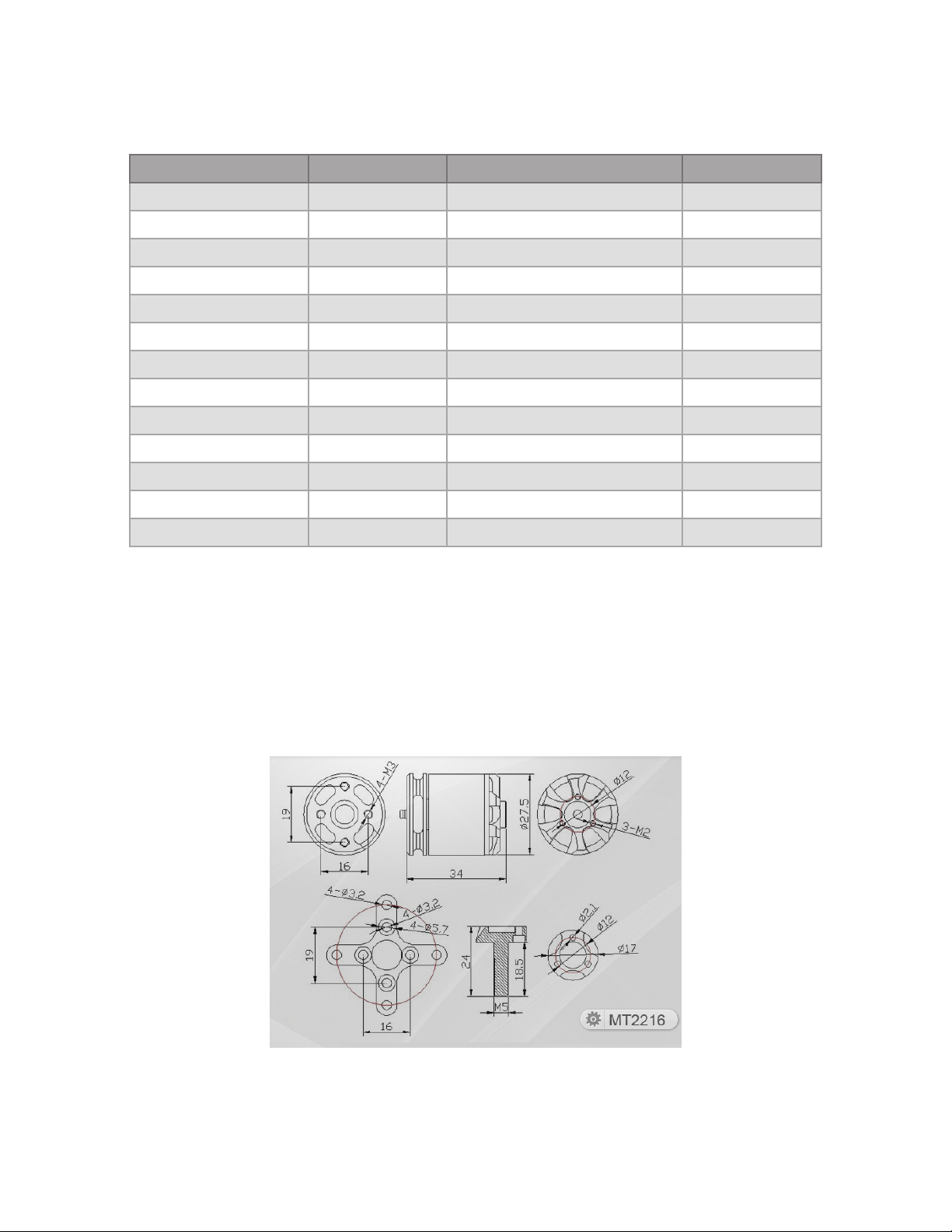
1.6 Propulsion
Solo uses four brushless, 880 KVmotors and four propellers for propulsion. For control and aerodynamic efficiency,
two motors spin clockwise and two motors spin counterclockwise. Navigation in the air is achieved by mixing
propulsion of the four motors to actuate flight control along the roll, pitch, and yaw axes.
Figure 1.6.1: Motor Schematic Diagram
Location Sensor Manufacturer / Part Number* Data Type
Pixhawk 2 FMU Accelerometer InvenSense / MPU6000 Orientation
Pixhawk 2 FMU Gyroscope InvenSense / MPU6000 Motion
Pixhawk 2 FMU Magnetometer Honeywell / HMC 5983 Cardinal direction
Pixhawk 2 FMU Barometer Measurement Specialties / MS5611 Altitude
Pixhawk 2 Stabilized IMU Accelerometer InvenSense / MPU6000 Orientation
Pixhawk 2 Stabilized IMU Gyroscope InvenSense / MPU6000 Motion
Pixhawk 2 Stabilized IMU Barometer Measurement Specialties / MS5611 Altitude
Pixhawk 2 Stabilized IMU Accelerometer STMicroelectronics / LSM303D Orientation
Pixhawk 2 Stabilized IMU Magnetometer STMicroelectronics / LSM303D Cardinal direction
Pixhawk 2 Stabilized IMU Gyroscope STMicroelectronics / L3GD20 Motion
3DR Solo GPS GPS u-blox / NEO-7N Longitude & latitude
3DR Solo GPS GPS patch antenna Taoglas / GP.1575.25.4.A.02 Longitude & latitude
3DR Solo Compass Magnetometer Honeywell / HMC 5983 Cardinal direction
Altri manuali per Solo
8
Questo manuale è adatto per i seguenti modelli
1
Indice
Altri manuali 3D R Drone

3D R
3D R Y6 Manuale utente

3D R
3D R X8-M Manuale utente

3D R
3D R IRIS Manuale utente

3D R
3D R Y6 Manuale utente

3D R
3D R IRIS+ Manuale utente

3D R
3D R H520-G Specifiche tecniche

3D R
3D R Solo Manuale utente

3D R
3D R ArduCopter Quad-C Manuale utente

3D R
3D R Solo Manuale utente

3D R
3D R LiveView Kit for GoPro Manuale utente


 Manuale utente")


