
3M 5458A-IJ Manuale utente

3M™ Cold Shrink Integrated Splice
Kit QS-III 5458A-IJ
for Jacketed Concentric Neutral (JCN) Cable
Instructions
IEEE Std. 404
25/28 kV Class
200 kV BIL
CAUTION
Working around energized systems may cause serious injury or death. Installation should
be performed by personnel familiar with good safety practice in handling electrical
equipment. De-energize and ground all electrical systems before installing product.
KitSelectionTable
Kit Number Cable Insulation O.D. Range Conductor Size Range
5458A-IJ 1.24"–2.07"
(31,5–52,6 mm)
500–1000 kcmil*
(240–500 mm2)
* Splices (including size transitions) can be made to smaller or larger conductors (but larger conductors may require special neutral
handling), provided both cables are within the Insulation O.D. Range and the connector meets the dimensional requirements
shownbelow.
ConnectorDimensionalRequirements
Minimum Inches (mm) Maximum Inches (mm)
Outside Diameter 1.05" (26,7 mm) 2.07" (52,6 mm)
Length
Aluminum (Al/Cu) Compression —7.50" (191 mm)
Length
Copper Compression and
3M™ Shearbolt Connector QCI 500-1000
—8.25" (210 mm)
September2010
78-8127-8872-3-B3

2 78-8127-8872-3-B
1.0 Kit Contents
a. 3M™ColdShrinkIntegratedSpliceBody5458A-IJ(1ea.)
b. ConstantForceSprings(4ea.)
c. RedCompoundTubes(non-siliconegrease)(2ea.)
d. Scotch®RubberMasticTape2228Rolls,2"x48"(2ea.)
e. Scotch®MasticSealingStrips2230,6"length(8ea.)
f. ColdShrinkAdapterTube(1ea.*)
g. 3M™CableCleaningPadsCC-3(1ea.)
h. Scotch®ElectricalShieldingTape24,1"x15'(1ea.)
i. 3M™AluminumFoilTapeStrips1115B,10"length(2ea.)
j. Cut-backTemplate(2ea.**)
k. InstructionBooklet(1ea.)
*Cold shrink adapter tube may not be included in all kits.
**Kits contain either 1 or 2 cut-back templates as needed per conductor size.
Note: Do not use knives to open plastic bags.
Note: Connector not shown, but if included, it is indicated on the packaging label.
78-8127-8872-3-B 3
2.0 Prepare Cables
2.1 Checktobesurethecablefitswithinthekitrangesasshownonthecoverpage.
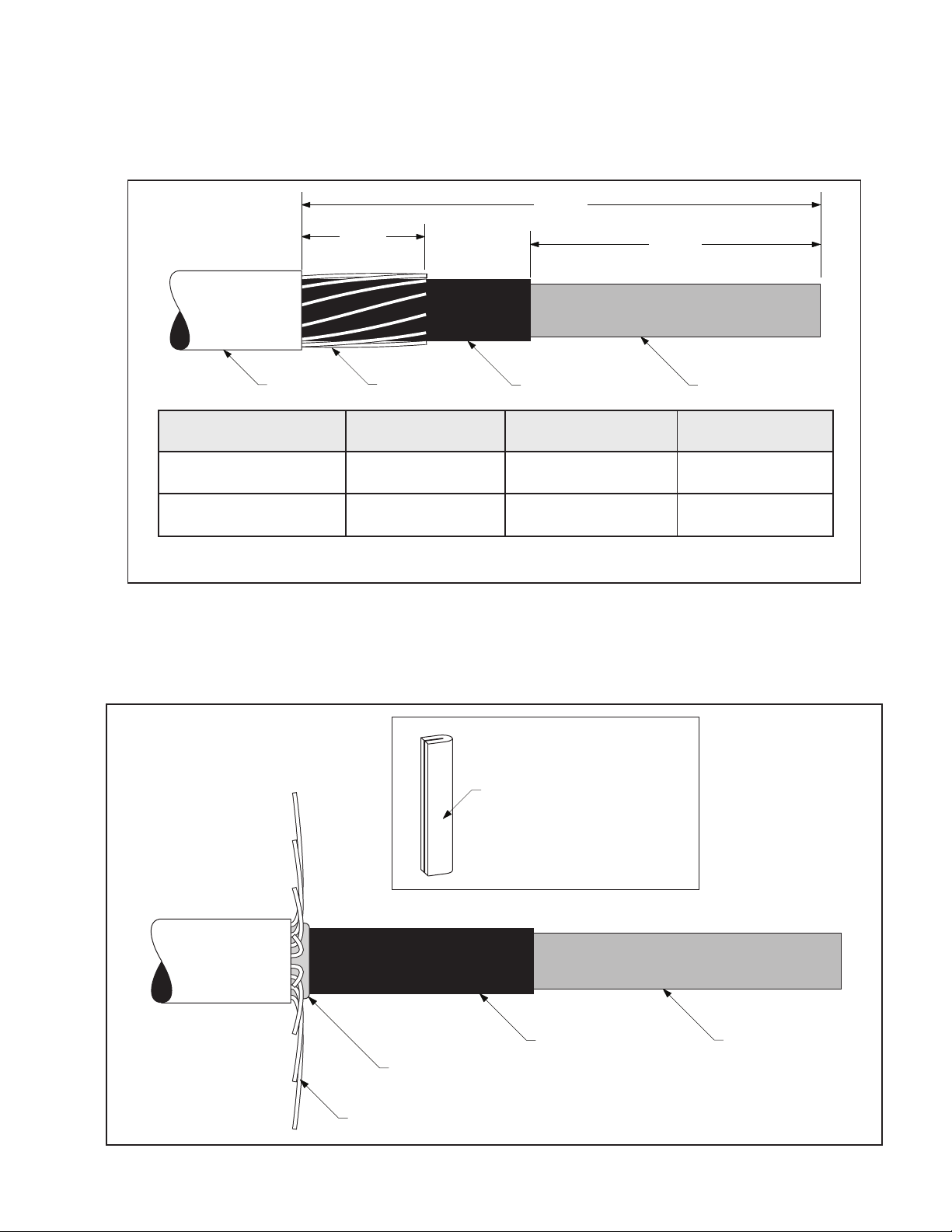
2.2 Preparecablesaccordingtostandardprocedures.Refertotemplateprovidedorillustrationbelowforproper
dimensions(Figure1).
“A”
“B”
3 1/2"
(89 mm)
Insulation
Semi-Con
Neutral Wires
Cable Jacket
Typical Conductor Size*
kcmil (mm2)
Insulation OD Range
Inches (mm)
Jacket Cutback "A"
Inches (mm)
Semi-con Cutback "B"
Inches (mm)
500**-750
(240-400)
1.24–1.70
(31,5–43,2)
15 3/4
(400)
9 1/4
(235)
1000**
(500)
1.59–2.07
(40,4–52,6)
15 1/4
(387 mm)
8 3/4
(222)
*For 100% and 133% insulation levels, Insulation OD is the final determining factor.
**Cables must be within the Insulation OD Range of the splice kit and the connector must meet the dimensional requirements shown on the front page.
Figure1
2.3 Carefullybendthecutneutralwiresupandawayfromthecablesemi-conasshown.FoldoneScotch®Mastic
SealingStrip2230inhalflengthwiseandapplyonewraponlyatcablejacketedgeundertheneutralwires
(Figure2).
Insulation
Semi-Con
Neutral Wires
Scotch® Mastic Sealing Strip 2230
Fold mastic strip in half lengthwise
Figure2
4 78-8127-8872-3-B
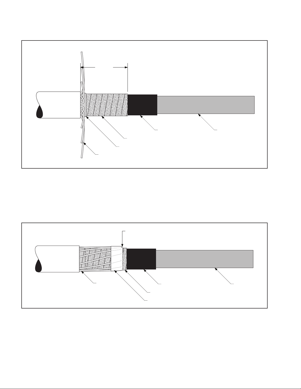
2.4 Markthecablesemi-con4"(102mm)fromthecablejacketedge.Applytwohalf-lappedlayersofScotch®
ElectricalShieldingTape24overthecablesemi-con,startingfromthemasticedgeouttothemarkonthe
semi-conandback.Half-hitchtotieoff(Figure3).
Insulation
Semi-Con
Neutral Wires
Scotch® Mastic Sealing Strip 2230
4"
(102 mm)
Scotch® Electrical Shielding Tape 24
Figure3
2.5 Carefullylayneutralwiresbackdownontopoftheshieldingtapeandpressintomastic.Keepwireprofilelow
byfollowingtheconcentricturninthecable(Figure4).
2.6 Removethelinerfromone3M™AluminumFoilTapeStrip1115Bandsecuretheendsoftheneutralwires.
Wrapthealuminumtapeontopofitselfandtightlypressdownontheedgeofthetapetowardtheendofthe
electricalshieldingtape(Figure4).
Insulation
Semi-Con
Neutral Wires
3M™ Aluminum Foil Tape Strip 1115B
Scotch® Electrical Shielding Tape 24
Press down edge tightly
Figure4

78-8127-8872-3-B 5
2.7 ApplyaScotch®MasticSealingStrip2230overthepreviouslyappliedmasticstripandoverlappingontothe
cablejacket.Kneadmasticaroundneutralwires.Overwrapmasticwithvinyltape,takingcarenottoextend
tapealongneutralwires(Figure5).
Scotch® Mastic Sealing Strip 2230
Overwrap with vinyl tape
Cable Jacket
Figure5
2.8 Cleanorcovercablejacket30"(760mm)fromjacketedgeonsidewheresplicebodywillbeparked.
2.9 Slideintegratedsplicebodyontocleancablejacket,loosecoreendfirst(Figure6).
Loose core end
Integrated splice body
Cleaned cable jacket
Figure6
3.0 Install Connector
Note: If using a crimp-type connector, go to step (3.3).
3.1 Ifusinga3M™ShearboltConnectorQCI500-1000,refertotheinstructionsincludedwiththeconnectorfor
insulationcut-backdimension.Insulationremovallengthshallnotexceed33/4"(95mm)fromconductorend
(Figure7).
Refer to connector instructions for dimensions
Figure7

6 78-8127-8872-3-B
3.2 Install3M™ShearboltConnectorQCI500-1000accordingtotheinstructionsincludedwiththeconnector
(Figure8).
Connector
Shearbolt
Figure8
Go to section 4.0 “Install Splice.”
3.3 Ifusingacrimptypeconnector,removecableinsulationfor1/2connectorlengthplusanallowance*for
increasesinconnectorlengthduetocrimping.Insulationremovallengthshallnotexceed4-1/8"(105mm)from
conductorend.Donotinstallconnectornow(Figure9).
*Note: This assumes that the installer has determined the increased length of an aluminum connector crimped
with a specific tool and die.
Aluminum (Al/Cu) Crimp Connector Growth Chart
Conductor Size Typical growth allowance (per end)
500 kcmil 1/4" (6 mm)
750–1000 kcmil 3/8" (10 mm)
Note: 1) Copper connectors do not require a length change allowance.
2) Maximum aluminum connector crimped length allowed is 8.25" (210 mm).
One-half connector length
+ growth allowance*
Figure9

78-8127-8872-3-B 7
3.4 For500kcmilcopperconnectors,orconnectorswithanO.D.between1.05–1.24"(26,7–31,5mm):
Parkcoldshrinkadaptertubeoncableinsulation(Figure10).
Cold shrink adapter tube
Figure10
3.5 Installconnector.Seetable(oncover)forproperconnectordimensions.(Forstandard3M™Connectors,refer
totableattheendofthisinstructionforcrimpinginformation).Removeanyexcessoxidationinhibitorfrom
connectorendsifaluminumconnectorisused(Figure11).
Connector
Figure11
4.0 Install Splice
4.1 Applyatapemarkertosemi-coninsulationshieldoncablewhichdoesnotcontainsplice.Measure11-1/2"
(292mm)fromcenterofconnector(Figure12).
Tape Marker
Semi-con
11 1/2"
(292 mm)
Figure12

8 78-8127-8872-3-B
4.2 Ifusingcoldshrinkadaptertube:Positionadaptertubeovertheconnector.Shrinkadapternearcenterof
connectorbypullingandunwindingtheloosecoreendinacounter-clockwisedirection(Figure13).
Cold shrink adapter tube
Figure13
4.3 Cleancablesusingstandardpractice:
a.Donotallowsolventorabrasivetocontactthecablesemi-conductiveinsulationshield.
b.Donotreducecableinsulationdiameterbelow1.24"(31,5mm)specifiedforthesplice.
c.Theinsulationsurfacemustberound,smoothandfreeofcuts/voids.Sandingmaybenecessary,finish
sandingshouldbedonewitha300gritorhigherelectricalgradeabrasive.
d.Makecertainthatthecableinsulationissmooth,cleananddrybeforecontinuing.
4.4 Applyredcompoundoncableinsulations,makingcertaintofillinedgeofcablesemi-con.Donotuse
siliconegrease(Figure14).
Apply Red
Compound
Apply Red
Compound
Fill semi-con step Fill semi-con step
Figure14

78-8127-8872-3-B 9
4.5 Positionthesplicebodyoverconnectorarea,aligningendofthesplicebody(notthecore)atthecenter
ofthetapemarker.Slowlystarttoremovethesplicecorebypullingandunwindingtheloosecoreend
counterclockwise,allowingonly¼"(6mm)ofthesplicetoshrinkontothetapemarker.Carefullyslidethe
splicebodyoffthetapemarkerbypullingandtwistinguntiltheentiretapemarkerisexposed.Continue
removingthecoretocompletethesplicebodyinstallation(Figure15).
Note: The splice body ends must overlap onto the semi-con of each cable by at least 1/2" (13 mm).
Note: Do not push the splice body toward the tape marker as this may cause the end to roll under. If the end
does roll under, DO NOT use sharp-edged tools to pull it out as this could cut and damage the splice.
Unwind Counter-clockwise
Align splice body with tape marker
Figure15
5.0 Connect Shielding
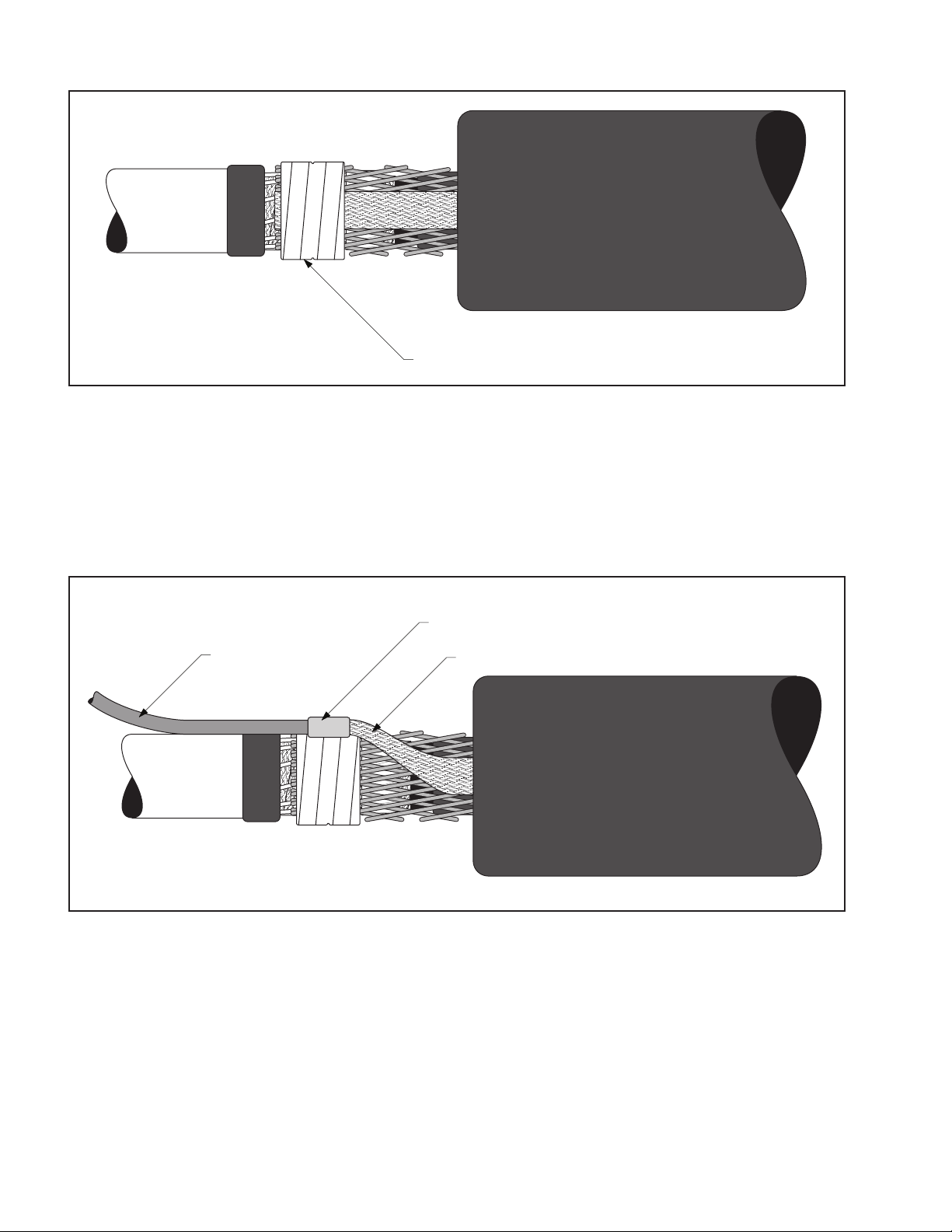
5.1 Removethevinyltapeholdingtheshieldsleeveontherejacketingtube,andspreadtheshieldsleeveouttoward
thecablejacket.
Note: The 3M™ Cold Shrink Integrated Splice Body includes a pre-installed ground braid for external
grounding on either side of the splice body. If not using the ground braid, it may be tied into the ground
system with the shield sleeve using constant force springs as shown below.
5.2 Hand-tightentheshieldsleeveoutwardandsecureit(alongwiththegroundbraidifnotgroundingexternally)
totheneutralwiresoneithersideofthespliceusingtwoconstantforcespringsoneachendbetweenthe
vinlytapeatthejacketedgeandthealuminumfoiltapeasshown.Trimexcessgroundbraidifneeded.Cinch
(tighten)thespringafterwrappingthefinalwinding(Figure16).
Ground Braid
Aluminum Foil Tape beneath Shield Sleeve
Constant Force Springs
Cable Jacket
Rejacketing Tube
Vinyl Tape
Figure16
10 78-8127-8872-3-B
5.3 Wraptwohalf-lappedlayersofvinyltapeovertheconstantforcesprings(Figure17).
Vinyl Tape
Figure17
6.0 External Grounding (Optional)
Note: Use these instructions if circuit grounding is required at this location.
6.1 Connectagroundwiretothepre-installedgroundbraidontheintegratedspliceusinganappropriateconnector.
Keepconnectorprofileaslowaspossible.ForC-taporH-tapconnectors,positionflatagainstthecable.Crimp
connectorfollowingtheconnectormanufacturer’srecommendations(Figure18).
Ground Wire
Connector
Ground Braid
Figure18
Altri manuali 3M Cavi e connettori

3M
3M 5415A-IJ Manuale utente

3M
3M 103 12R1-00 Series Manuale utente

3M
3M 4075 Guida

3M
3M Crimplok 8700-PS/APC Manuale utente

3M
3M Litmann Quality 3100 Manuale utente

3M
3M 8800-APC/AS/AGC Manuale utente

3M
3M Fibrlok II 2539 Manuale utente

3M
3M 3104 Manuale utente

3M
3M TTS-5-1-OJ Guida utente

3M
3M 7620-S-2 Manuale utente

3M
3M 7700 Series Istruzioni operative

3M
3M 3443-112 Istruzioni per il montaggio

3M
3M 50P Guida di riferimento

3M
3M Liqui-Cel MM 0.5x1 Series Manuale

3M
3M Cold Shrink QT-III 7620-S-INV-3G Series Manuale utente

3M
3M 5810 Series Manuale utente

3M
3M ECAM-27MM-D Manuale utente

3M
3M 36110-3000 Series Manuale utente

3M
3M 5300 Series Manuale utente

3M
3M 4655 Manuale utente


