3M DBI-SALA 8000140 Manuale utente

© 3M 2023
USER INSTRUCTIONS
5908150 Rev. A
3M™ DBI-SALA®
TRIPOD
;For identication of product codes, refer to Table 1. See “Table 1 - Product Specications” for more product information.
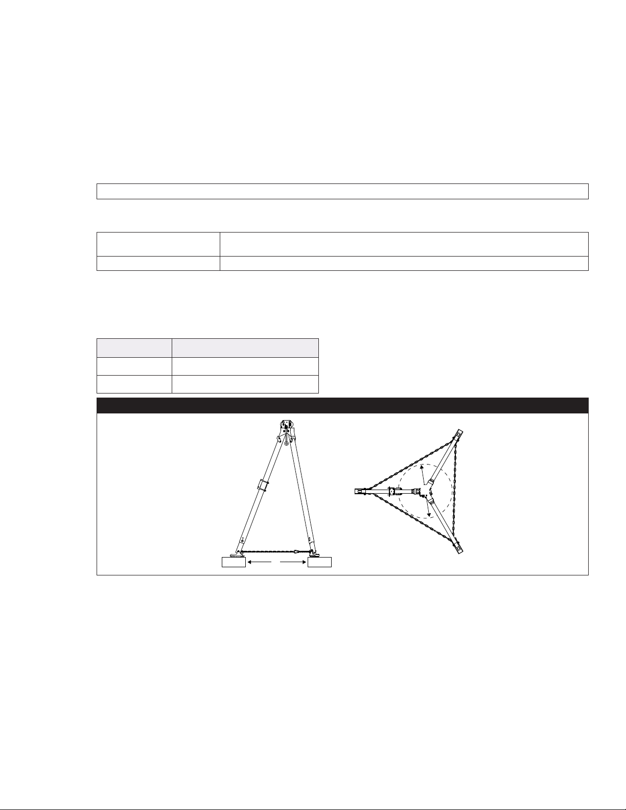
Figure 1 - Product Overview
Model D1 D2 D3 Weight
8000140 68 in. (172.7 cm) at lowest position;
93 in. (236.2 cm) at highest position 70 in. (177.8 cm) 58 in. - 77 in.
(147.3 cm - 195.6 cm) 47 lb. (21 kg)
8000141 96 in. (243.8 cm) at lowest position;
118 in. (299.7 cm) at highest position 102 in. (259 cm) 79 in. - 96 in.
(200.7 cm - 243.8 cm) 56 lb. (25 kg)
D1
D2
D3
OSHA 29 CFR 1910.140
OSHA 29 CFR 1926.502

FORM NO: 5908277 REV: B 2
SAFETY INFORMATION
Please read, understand, and follow all safety information contained in these instructions, prior to the use of this product. FAILURE TO DO SO
COULD RESULT IN SERIOUS INJURY OR DEATH.
These instructions must be provided to the user of the equipment. Retain these instructions for future reference.
Intended Use:
This product is used as part of a complete Fall Protection system.
Use in any other application including, but not limited to, non-approved material handling, recreational or sports-related activities, or other activities not
described in these instructions, is not approved by 3M and could result in serious injury or death.
This product is only to be used by trained users in workplace applications.
!WARNING
This product is used as part of a complete Fall Protection system. All users must be fully trained in the safe installation and operation of their complete Fall
Protection system. Misuse of this product could result in serious injury or death. For proper selection, operation, installation, maintenance, and service,
refer to all instruction manuals and manufacturer recommendations. For more information, see your supervisor or contact 3M Technical Services.
• To reduce the risks associated with using a Conned Space Entry-Rescue System which, if not avoided, could result in serious injury or
death:
- Inspect the product before each use and after any fall event, in accordance with the procedures specied in these instructions.
- If inspection reveals an unsafe or defective condition, remove the product from service immediately and clearly tag it “DO NOT USE”. Destroy or
repair the product as required by these instructions.
- Any product that has been subject to fall arrest or impact force must be immediately removed from service. Destroy or repair the product as
required by these instructions.
- Ensure that Fall Protection systems assembled from components made by dierent manufacturers are compatible and meet all applicable Fall
Protection regulations, standards, or requirements. Always consult a Competent or Qualied Person before using these systems.
- The product must only be installed as described in its instruction manuals. Installations and use outside the scope of these instruction manuals must
be approved in writing by 3M.
- Only connect Fall Protection subsystems to the designated anchorage connection points on the product.
- Before installing, ensure that the installation methods and the product will not interfere with electric lines, gas lines, or other critical materials or
systems.
- Ensure the product is congured and installed properly for safe operation as described in these instructions.
- Do not exceed the number of allowable users specied in these instructions.
- Do not twist, tie, knot, or allow slack in the lifeline.
- Do not connect to the system while it is being transported or installed.
- Use caution when installing, using, or moving the product as moving parts may create pinch points.
- Lockout/tagout procedures must be followed when applicable.
- Ensure the lifeline of your connecting subsystem does not extend outside the legs of the tripod.
- Never use the tripod without the leg chains secured.
• To reduce the risks associated with working at height which, if not avoided, could result in serious injury or death:
- Your health and physical condition must allow you to safely work at height and to withstand all forces associated with a fall arrest event. Consult
your doctor if you have questions regarding your ability to use this equipment.
- Never exceed allowable capacity of your Fall Protection equipment.
- Never exceed the maximum free fall distance specied for your Fall Protection equipment.
- Do not use any Fall Protection equipment that fails inspection, or if you have concerns about the use or suitability of the equipment. Contact 3M
Technical Services with any questions.
- Some subsystem and component combinations may interfere with the operation of this equipment. Only use compatible connections. Contact 3M
Technical Services before using this equipment in combination with components or subsystems other than those described in these instructions.
- Use extra precautions when working around moving machinery, electrical hazards, extreme temperatures, chemical hazards, explosive or toxic
gases, sharp edges, abrasive surfaces, or below overhead materials that could fall onto you or your Fall Protection equipment.
- Ensure use of your product is rated for the hazards present in your work environment.
- Ensure there is sucient fall clearance when working at height.
- Never modify or alter your Fall Protection equipment. Only 3M, or persons authorized in writing by 3M, may make repairs to 3M equipment.
- Before using Fall Protection equipment, ensure a written rescue plan is in place to provide prompt rescue if a fall incident occurs.
- If a fall incident occurs, immediately seek medical attention for the fallen worker.
- Only use a full body harness for Fall Arrest applications. Do not use a body belt.
- Minimize swing falls by working as directly below the anchorage point as possible.
- A secondary Fall Protection system must be used when training with this product. Trainees must not be exposed to an unintended fall hazard.
- Always wear appropriate Personal Protective Equipment when installing, using, or inspecting the product.
- Never work below a suspended load or worker.
- Always maintain 100% tie-o.
ENEN

3
;Always ensure you are using the latest revision of your 3M instruction manual. Visit www.3m.com/userinstructions or
contact 3M Technical Services for updated instruction manuals.
PRODUCT OVERVIEW:
Figure 1 identies available product models. Tripods are adjustable systems that may secure connecting subsystems in various
congurations for use in conned space applications. This product may be used in Fall Arrest, Rescue, and Work Positioning
applications.
Figure 2 identies key components of the available product models. The Head Mount Pulley (A) routes the lifeline of the user’s
primary subsystem, which is secured by a pin atop the pulley. Below the tripod head, the Eye Bolt (B) may also be used to
secure a connecting subsystem. The Leg Lock (C) secures the Tripod Leg (D) in place during use. The length may be adjusted
and secured with use of each leg’s Adjustment Pin (E). The Tripod Foot (F) levels the tripod and routes the Tripod Chain (G),
which secures the tripod legs. The Mounting Bracket (H) receives a connecting subsystem for routing through the tripod pulleys.
There are a number of accessories that may be used with this product. Additional Mounting Brackets (8005048) may be
purchased for securing connecting subsystems to the tripod. The Leg Mount Pulley (8003238) attaches to a tripod leg and may
be used to route an additional lifeline. The Snatch Block Pulley (8003205) is secured to the eye bolt and is an additional means
of routing a lifeline. All accessories are sold separately.
See Table 1 for more information on Component Specications.
Figure 2 - Components
A
B
C
F
G
H
E
D
8003205 8003238 8005048

4
;Before using this equipment, record the product identication information from the ID label in the ‘Inspection and
Maintenance Log’ at the back of this manual.
Table 1 – Product Specications
System Specications:
User Capacity: The user capacity of this system is determined by its maximum static strength. See Section 4 for
more information.
Material Handling: This product may be used for material handling as described in these instructions. See Section 4 for
more information.
Standards: Each product model is certied to, or conforms with, the applicable standards and regulations listed
within Figure 1. If none are specied, then all standards and regulations listed on the cover apply.
Component Specications:
Figure 2
Reference Component Materials
A Head Mount Pulley Zinc-plated steel
B Eye Bolt Zinc-plated steel
C Leg Lock Zinc-plated steel
D Tripod Leg Aluminum
E Adjustment Pin Zinc-plated steel
FTripod Foot Aluminum, rubber
G Tripod Chain Zinc-plated steel
HMounting Bracket Zinc-plated steel
Accessories:
Model
Number Component Materials
8003205 Snatch Block Pulley Zinc-plated steel
8003238 Leg Mount Pulley Zinc-plated steel, nylon plastic
8005048 Mounting Bracket Zinc-plated steel

5
1.0 PRODUCT APPLICATION
1.1 PURPOSE: Conned space systems are products designed for use in work areas with limited room or maneuverability.
System applications vary with the product. For more information on system applications, refer to the “Product Overview”
and Table 1.
1.2 SUPERVISION: Use of this equipment must be supervised by a Competent Person. Installation must be supervised by a
Qualied Person.
1.3 STANDARDS: Your product conforms to the national or regional standards identied on the front cover of these
instructions. If this product is resold outside the original country of destination, the re-seller must provide these
instructions in the language of the country in which the product will be used.
;For more information on certication or conformance requirements, refer to the applicable standards and
regulations listed for your product (e.g. the ANSI/ASSP Z359 Fall Protection codes).
1.4 TRAINING: This equipment must be installed and used by persons trained in its correct application. These instructions are to be used
as part of an employee training program as required by national, regional, or local standards. It is the responsibility of the users and
installers of this equipment to ensure they are familiar with these instructions, trained in the correct care and use of this equipment,
and are aware of the operating characteristics, application limitations, and consequences of improper use of this equipment.
1.5 RESCUE PLAN: When using this equipment and connecting subsystems, the employer must have a written rescue plan and
the means to implement and communicate that plan to users, authorized persons, and rescuers. A trained, on-site rescue team
is recommended. Team members should be provided with the equipment and techniques necessary to perform a successful
rescue. Training should be provided on a periodic basis to ensure rescuer prociency. Rescuers should be provided with these
instructions. There should be visual contact or means of communication with the person being rescued at all times during the
rescue process.
2.0 SYSTEM REQUIREMENTS
2.1 ANCHORAGE: The anchorage structure securing this product must be able to withstand any required loads as permitted by its
Fall Protection system. See Section 4 for more information.
2.2 CAPACITY: The user capacity of a complete Fall Protection system is limited by its lowest rated maximum capacity component.
For example, if your connecting subsystem has a capacity that is less than your harness, you must comply with the capacity
requirements of your connecting subsystem. See the manufacturer instructions for each component of your system for capacity
requirements.
2.3 ENVIRONMENTAL HAZARDS: Use of this equipment in areas with environmental hazards may require additional
precautions to prevent injury to the user or damage to the equipment. Hazards may include, but are not limited to: high
heat, chemicals, corrosive environments, high voltage power lines, explosive or toxic gases, moving machinery, sharp
edges, or overhead materials that may fall and contact the user or equipment. Contact 3M Technical Services for further
clarication.
2.4 LIFELINE HAZARDS: Ensure the lifeline is kept free from all hazards including, but not limited to: entanglement with
users, other workers, moving machinery, other surrounding objects, or impact from overhead objects that could fall onto
the lifeline or users.
2.5 COMPONENT COMPATIBILITY: 3M equipment is designed for use with 3M equipment. Use with non-3M equipment
must be approved by a Competent Person. Substitutions made with non-approved equipment may jeopardize equipment
compatibility and may aect the safety and reliability of your Fall Protection system. Read and follow all instructions and
warnings for all equipment prior to use.
2.6 CONNECTOR COMPATIBILITY: Connectors are compatible with connecting elements when the size and shape of either
component does not cause the connector to inadvertently open, regardless of orientation. Connectors must comply with
applicable standards. Connectors must be fully closed and locked during use.
3M Connectors (snap hooks and carabiners) are designed to be used only as specied in each instruction manual. Ensure
connectors are compatible with the system components to which they are connected. Do not use equipment that is non-
compatible. Use of non-compatible components may cause the connector to unintentionally disengage (see Figure 3). If
the connecting element to which a connector attaches is undersized or irregular in shape, a situation could occur where
the connecting element applies a force to the gate of the connector (A). This force could then cause the gate to open (B),
disengaging the connector from the connecting element (C).

6
2.7 MAKING CONNECTIONS: All connections must be compatible in size, shape, and strength. See Figure 4 for examples of
inappropriate connections. Do not attach snap hooks and carabiners:
A. To a D-Ring to which another connector is attached.
B. In a manner that would result in a load on the gate. Large-throat snap hooks should not be connected to D-Rings or
other connecting elements, unless the snap hook has a gate strength of 16 kN (3,600 lbf) or greater.
C. In a false engagement, where size or shape of the connector or connecting element is not compatible and, without
visual conrmation, would seem to be fully engaged.
D. To each other.
E. Directly to harness webbing, lanyard leg material, or tie-back material unless such a connection is explicitly allowed
for by the manufacturer instructions.
F. To any object whose size or shape does not allow the connector to fully close and lock, or that could cause connector
roll-out.
G. In a manner that does not allow the connector to align properly while under load.
Figure 3 - Connector Compatibility Figure 4 - Making Connections
A. B. C. D.
E. F. G.
A B C
7
3.0 INSTALLATION
3.1 OVERVIEW: Conned space systems must be installed as described in their manufacturer instructions. All system
requirements must be met as described. Eective planning and awareness of your worksite and your equipment are of
great help in making this process move as smoothly as possible.
3.2 PLANNING: Plan your Fall Protection system before starting your work. Account for all factors that may aect your safety
before, during, and after a fall. Consider all requirements and limitations specied in these instructions.
A. SHARP EDGES: Avoid working where system components may be in contact with, or scrape against, unprotected
sharp edges and abrasive surfaces. All sharp edges and abrasive surfaces should be covered with protective material.
B. NUMBER OF USERS: The number of users that may secure to this product is limited by the weight of those users
and the maximum static load that can be expected with their use of the product. The maximum static load expected
through use of this product must always be equal to or less than its maximum static strength. See Section 4 for more
information about user capacity.
;The number of users may also be limited by product design.
C. COMPATIBILITY: When installing your system, it is important that you use compatible components. Each product
model is compatible for use with a specic set of product models or designs.
Self-Retracting Devices
(SRDs) The maximum arresting force for connecting subsystems must meet the requirements
listed in Section 4.
Winches Use must not exceed the lifting capacity of the winch.
D. SECONDARY SYSTEMS: When using this product for Work Positioning applications, a secondary or backup Fall
Arrest system is recommended and may be required by some standards.
E. DIMENSIONS AND WORKING AREA: Before installing the tripod, the user should conrm that their working area
will t the tripod. The tripod feet must be planted rmly on the working surface, outside the hole or opening where
users will be raised or lowered.
Model Number Opening Diameter (A)
8000140 23 in. - 32 in. (58.4 cm - 81.3 cm)
8000141 33 in. - 44 in. (83.8 cm - 111.7 cm)
Figure 5 - Working Area
A
A
3.3 INSTALLING THE TRIPOD: See Figure 6 for reference. To install the tripod:
1. Prepare the tripod. Lay the tripod at on the ground and adjust each leg to the proper height. Use the adjustment
pins to set each leg at its selected position.
2. Spread the tripod legs. Position the tripod upright and spread each tripod leg. Pull the leg out to release its spring,
then set the leg at its full width. Once set, release the leg to re-engage the spring and secure the leg lock.
3. Position the tripod. Place the tripod over the opening so that the lifeline of any secured connecting subsystem will
be routed through the center of the opening. Level the tripod by adjusting the height of the tripod legs.
4. Secure the tripod chain. Route the tripod chain through the rings at the bottom of each tripod leg. Adjust the
length of the tripod chain to match the spread of the tripod legs, then secure the chain with its connector.
5. Complete nal system setup. Before using the tripod, secure any additional equipment and connecting subsystems
as necessary for your conguration.
A. Connect any additional equipment. This includes any additional pulleys or brackets that may be needed for
your connecting subsystem. See “Connecting Additional Equipment” for more information.
B. Secure any connecting subsystems. Connecting subsystems may be secured to the Eye Bolt (A) or to a
Mounting Bracket (B) installed on a tripod leg. Route the subsystem lifeline through one of the tripod pulleys.
See “Securing Connecting Subsystems” for more information.

8
Figure 6 - Installing the Tripod
12345
A
B
3.4 CONNECTING ADDITIONAL EQUIPMENT: Additional equipment may be necessary depending on your system’s
conguration.
A. MOUNTING BRACKETS: Mounting brackets are used to secure a winch or Self-Retracting Device (SRD) to the
tripod. To install a mounting bracket, position the bracket at the desired location on a tripod leg, then secure with the
provided fasteners. Tighten fasteners to 15 ft-lb. (20.3 N-m). See Figure 7 for reference.
;Never install mounting brackets onto the telescoping portion of the tripod legs.
Figure 7 - Connecting Mounting Brackets
B. PULLEYS: The user’s primary subsystem should route through the built-in head mount pulleys. Additional pulleys
may be installed when additional connecting subsystems are used. See Figure 8 for reference.
;All tripod pulleys can accommodate lifelines with diameters up to 1/4 in. (6 mm).
1. Leg Mount Pulley: The leg mount pulley is secured to one of the tripod legs. Position the leg mount pulley
within 12 in. (30.5 cm) of the leg lock. Secure the pulley to the tripod leg using the provided fasteners. Tighten
fasteners to 15 ft-lb. (20.3 N-m).
;It may be necessary to remove one of the tripod’s eye bolts to gain clearance for the lifeline.
2. Snatch Block Pulley: The snatch block pulley is secured to one of the eye bolts. Secure the pulley to the eye
bolt using the provided pin.
;Never route winch lifelines through the snatch block pulley.
Figure 8 - Connecting Additional Pulleys
8.1 8.2
<12 in.
(30.5 cm)

9
3.5 SECURING CONNECTING SUBSYSTEMS: Connecting subsystems may be secured to one of the tripod’s eye bolts or
onto a mounting bracket. See Figure 9 for reference. To secure a connecting subsystem:
;This product may have a total of four connecting subsystems secured at any given time. This includes two primary
subsystems and two secondary subsystems.
;See “Planning” for more information on connecting subsystem compatibility.
A. EYE BOLTS: Secure the connecting subsystem to the eye bolt using the connector atop the connecting subsystem.
Alternatively, a clevis pin may be used.
B. MOUNTING BRACKETS: Place the connecting subsystem’s bracket onto the mounting bracket, aligning the holes
in the two brackets. Secure the brackets by threading the locking pin on the subsystem bracket through the aligned
bracket holes. Thread the lifeline of the connecting subsystem through one of the tripod pulleys.
;It is recommended that you thread your primary subsystem’s lifeline through the head mount pulleys.
;Never secure two connecting subsystems to the same tripod leg.
Figure 9 - Securing Connecting Subsystems
4.0 USE
4.1 BEFORE EACH USE: Verify that your work area and Fall Protection system meet all criteria dened in these instructions.
Verify that a formal Rescue Plan is in place. Inspect the product per the ‘User’ inspection points dened in the “Inspection
and Maintenance Log”. If inspection reveals an unsafe or defective condition, or if there is any doubt about its condition
for safe use, remove the product from service immediately. Clearly tag the product “DO NOT USE”. See Section 5 for more
information.
4.2 ANCHORAGE: In addition to product capacity, any fall protection system must take into account the strengths of any
supporting structures or components.
A. ANCHORAGE STRUCTURE: The anchorage structure securing this product must be able to withstand the required
loads, as permitted by this product’s fall protection system.
Static Load 5,000 lbf (22.2 kN)
B. ANCHORAGE CONNECTION POINTS: Anchorage connection points used with the product must be able to
withstand any loads applied by the product.

10
4.3 USER CAPACITY: The user capacity of this product is determined by its maximum static strength. Maximum static
strength is dened by the applicable standard or regulation and states the maximum static load that the product can
withstand. The maximum static load for your system must always be equal to or less than the product’s maximum static
strength.
;When using this product, you may use one of the example congurations provided, or you may design your own
conguration using the described methods.
;Maximum arresting force is limited by the user’s connecting subsystem.
A. USER CAPACITY - OSHA
To calculate your maximum static load, double the maximum arresting force of your connecting subsystem and add
twice the weight of any additional users beyond the rst.
;OSHA static load and static strength values as tested include a 2:1 safety factor.
Maximum Static Strength 5,000 lbf (22.2 kN)
Primary Subsystem Location Maximum Arresting Force
Eye Bolt (A) 1,800 lbf (8 kN)
Mounting Bracket (B) 1,500 lbf (6.7 kN)
See Figure 10 for reference. Each user’s primary subsystem must have a maximum arresting force less than or equal
to the limit for its mounting point, whether it is an eye bolt or mounting bracket.
The following example congurations may be used in compliance with these regulations.
Maximum Arresting Force: 1,350 lbf (6 kN)
Number of
Users Maximum
User Weight Maximum
Static Load
Primary Subsystem Location
User 1 User 2
1 user Not applicable 2,700 lbf (12 kN) A or B ---
2 users 420 lb. (191 kg) 3,540 lbf (15.8 kN) A or B A or B
Maximum Arresting Force: 1,500 lbf (7 kN)
Number of
Users Maximum User Weight Maximum Static Load Primary Subsystem Location
User 1 User 2
1 user Not applicable 3,000 lbf (13.3 kN) A or B ---
2 users 420 lb. (191 kg) 3,540 lbf (15.7 kN) A or B A or B
Maximum Arresting Force: 1,800 lbf (8 kN)
Number of
Users Maximum User Weight Maximum Static Load Primary Subsystem Location
User 1 User 2
1 user Not applicable 3,600 lbf (16.0 kN) A ---
2 users 420 lb. (191 kg) 4,440 lbf (18.7 kN) A B (≤1,500 Maximum
Arresting Force)
Figure 10 - Tripod Mounting Locations
A
B
Questo manuale è adatto per i seguenti modelli
1
Indice
Lingue:
Altri manuali 3M Accessori per fotocamere


