Acer AF705 Manuale utente

1
AF705
Service Guide
17-inch CRT Monitor

2
Table of Contents
1. DISPLAY ALIGNMENT............................................................................... 3
A. TIMING & DISPLAY SIZE ....................................................................................................................... 3
B. PICTURE POSITION .............................................................................................................................. 3
C. LINEARITY ............................................................................................................................................. 3
D. ALIGNMENT PROCEDURE ................................................................................................................... 3
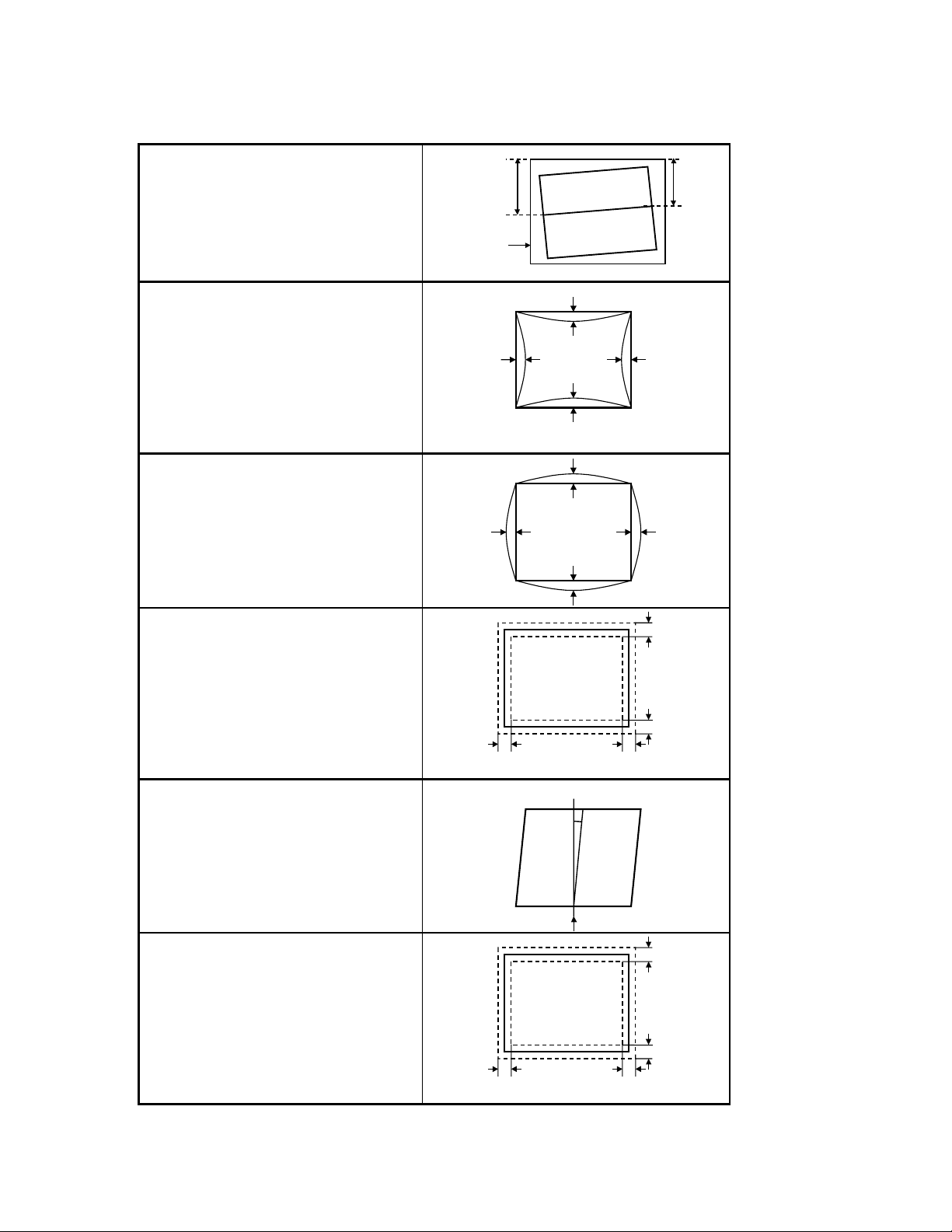
E. GEOMETRIC DISTORTION ................................................................................................................... 4
F. WHITE BALANCE ALIGNMENT.............................................................................................................. 5
2. CONTROL AND CONNECT LAYOUT ....................................................... 7
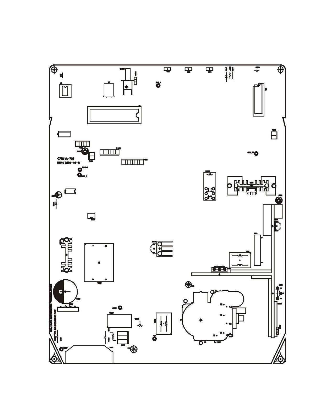
A. MAIN PCB .............................................................................................................................................. 7
C. PIN ASSIGNMENT ................................................................................................................................. 9
3. INTRODUCTION: ..................................................................................... 10
A. POWER SUPPLY ................................................................................................................................. 10
B. DEFLECTION: ...................................................................................................................................... 10
C. VIDEO: ................................................................................................................................................. 10
D. DIGITAL CONTROLLOR: ..................................................................................................................... 10
4. POWER SUPPLY ..................................................................................... 12
A. RECTIFIER AND FILTER CKT:............................................................................................................. 13
B. FLYBACK AND PWM CKT :.................................................................................................................. 13
C. SNUBBER CKT:.................................................................................................................................... 13
D. SYNCHRONIZED CKT: ........................................................................................................................ 13
E. POWER SAVING CKT: ......................................................................................................................... 13
F. DEGAUSS CKT: .................................................................................................................................... 14
G. OVERLOAD PROTECTION CKT:......................................................................................................... 14
5. DEFLECTION ........................................................................................... 14
A. SYNC RPOCESSOR: ........................................................................................................................... 15
B. HORIZONTAL PROCESSOR ............................................................................................................... 15
C. VERTICAL OUTPUT............................................................................................................................. 15
D. HORIZONTAL OUTPUT STAGE........................................................................................................... 15
E. FLYBLACK TRANSFORMER ............................................................................................................... 15
6. VIDEO AMP. CIRCUIT .............................................................................. 17
A. VIDEO PRE. AMP. ................................................................................................................................ 18
B. VIDEO AMPLIFIER ............................................................................................................................... 18
7. TROUBLESHOOTING ............................................................................. 19
A. POWER SUPPLY CHECK .................................................................................................................... 20
B. MONITOR CHECK FLOW CHART ....................................................................................................... 21
APPENDIX A: PARTS LIST ....................................................................... 23
APPENDIX B: P. C. B. ASSEMBLY ............................................................ 57
APPENDIX C: DISPLAY UNIT ASSEMBLY ............................................... 75
APPENDIX D: CRT & YOKE ASSEMBLY .................................................. 79

3
1. DISPLAY ALIGNMENT
A. TIMING & DISPLAY SIZE
For all presetting mode shall be within the limitation:
H. WIDTH 310 ±5mm
V. HEIGHT 232 ±3 mm
The external control range of the data area, shall be as follows;
Max. horizontal size : full the screen
Max. vertical size : full the screen
B. PICTURE POSITION
For all presetting mode shall be within the limitation:
H.PHASE SCREEN CENTE ±4 mm
V.CENTER SCREEN CENTE ±3 mm
C. LINEARITY
The linearity of an image displayed on the CRT must meet the following requirements, with reference to figure
4.05 for both X and Y and axis.
The measured value of linearity shall be less than 6%(p) or 8%(s) when calculated using all lattices and shall be
less than 5%(p) or 6%(s) when calculated using adjcent lattices.
Xmax-Xmin OR Ymax-Ymin
Xmax+Xmin Ymax+Ymin
Where: Xmax,Xmin,be Calculated Same Line
Ymax,Ymin,be Calculated Same Row
D. ALIGNMENT PROCEDURE
●Warm up the monitor for at least 30 minutes before adjustment.
●Set the front of CRT to the east.
●Turn all VR set to center position.
D-1. H.V
1. Use front control key adjust the display size about 300mm, adjust VR801 Let the Plus of C824 is
28.14V in Timing 68kmode FULL WHITE PATTERN, it can be got a stable H.V.

4
E. GEOMETRIC DISTORTION
E-1 Raster Rotation
SignalNo.1to6
|a - b |≤2.0 mm
a
b
Bezel
E-2 Pincushion
SignalNo.1to6
Top :d1 ≤2.0 mm
Bottom :b1 ≤2.0 mm
Leftside :a1 ≤1.5 mm
Rightside :c1 ≤1.5 mm
a1
b1
c1
d1
E-3 Barrel
Signal No.1 to 6
Top :d2 ≤2.0 mm
Bottom :b2 ≤2.0 mm
Leftside :a2 ≤1.0 mm
Rightside :c2 ≤1.0 mm
a2
b2
c2
d2
E-4 Trapezoid
Signal No.1 to 6
Top :d ≤2.5 mm
Bottom :b ≤2.5 mm
Leftside :a ≤2.5 mm
Rightside :c ≤2.5 mm
c
b
a
d
E-5 . Parallelogram
Signal No.1 to 6
a ≤0.5 degree
a
E-6 Overall Distortion
Signal No.6 only
Top :d ≤2.5 mm
Bottom :b ≤2.5 mm
Leftside :a ≤2.5 mm
Rightside :c ≤2.5 mm
c
b
a
d

5
F. WHITE BALANCE ALIGNMENT
?? F.1.1 Select timing #6 (VESA 68K 1024X768) with crosshatch pattern, adjust both horizontal and vertical
OSD’s size control to get display size within 310x232p±2mm.
?? F.1.2 Disconnect R.G.B. signal inputs, adjust OSD’s brightness and G1 control to it’s maximum position.
F.1.3 Auto alignment(P103 must be short)
Use automatic alignment equipment and program to get color temperature within specified coordinates.
F.1.4 Manual alignment
P103 must be short in order to into factory mode. Select OSD function to color temperature adjustment.
F.1.5 For 9300( 7500 ; 6500 ) color coordinate ( notes: set the minimum value of R.G.B. bias is 0,
setthevalueofsub-contrast“SC”is0).
F.1.6 Disable the video pattern( for a raster pattern ), set the maximum value of contrast and
brightness is 255, adjust G1 to Y=0.01 cd/mm
F.1.7 Adjust bias G to get Y=1.8 ±0.06 cd/mm
Adjust bias B to get y=297 ( y=315 for 7500 ; y=329 for 6500 ) ±5
Adjust bias R to get x=283 ( x=295 for 7500 ; x=313 for 6500 ) ±3
F.1.8 Fine tune the bias G and R for x=283 , y=297 ( x=299, y=315 for 7500; x=313, y=329 for
6500) ±3.
F.1.9 Select 7500 and 6500 color coordinate separately. Repeat item 2.5.5 ~ 2.5.8 to
meetspecificity.
F.1.10 Adjust brightness control to get raster is <= 0.25cd/mm, change pattern to 2 inch square.
F.1.11 Enable G signal output of pattern generator, adjust gain G to get Y=98 ± 1 cd/mm
F.1.12 Enable B signal output, adjust gain B to get y=297 ( y=315 for 7500 ; y=329 for 6500 ) ±2
Enable B signal output, adjust gain R to get x=283 ( x=299 for 7500 ; x=313 for 6500 )
±
1
??
F.1.13 Fine tune the gain G and R for x=283 , y=297
( x=299, y=315 for 7500; x=313, y=329, for 6500 )
±
2
F.1.14 Check 150 >Y> 130 cd/mm, if not , adjust G to get Y>130 cd/mm, then repeat item 2.5.12
F.1.15 Change pattern to fall white, adjust SB to get 92< Y <113 cd/mm .
F.1.16 Select 7500 and 6500 color coordinate separately. Repeat item 2.5.11 ~ 2.5.15 to meet
specificity. 7500 X=300 Y=315 6500 X=313 Y=329

6
G. PRESET TIMING
Preset Timing Chart
No
Signal Name Clock
(MHz)
Fh
(kHz)
Fv
(Hz)
Th
(uSec)
(dot)
Tsh
(uSec)
(dot)
Tfh
(uSec)
(dot)
Tbh
(uSec)
(dot)
Tdh
(uSec)
(dot)
Tv
(mSec)
(line)
Tsv
(mSec)
(line)
Tfv
(mSec)
(line)
Tbv
(mSec)
(line)
Tdv
(mSec)
(line)
Hs
Vs
1
VGA
640*480(60) 25.175 31.469 59.940 31.778
(800)
3.813
(96)
0.636
(16)
1.907
(48)
25.422
(640)
16.683
(525)
0.064
(2)
0.318
(10)
1.049
(33)
15.253
(480) - -
2
VESA
800*600(85) 56.250 53.674 85.061 18.631
(1048)
1.138
(64)
1.138
(64)
2.702
(152)
14.222
(800)
11.7 56
(631)
0.056
(3)
0.019
(1)
0.503
(27)
11.179
(600) + +
3
VESA
1024*768(85) 94.500 68.677 84.997 14.561
(1376)
1.016
(96)
0.508
(48)
2.201
(208)
10.836
(1024)
11.7 65
(808)
0.044
(3)
0.015
(1)
0.524
(36)
11.183
(768) + +
4
VESA
800*600(75) 49.500 46.875 75.000 21.333
(1056)
1.616
(80)
0.323
(16)
3.232
(160)
16.162
(800)
13.333
(625)
0.064
(3)
0.021
(1)
0.448
(21)
12.800
(600) + +
5
VESA
1024*768(75) 78.750 60.023 75.029 16.66
(1312)
1.219
(96)
0.203
(16)
2.235
(176)
13.003
(1024)
13.328
(800)
0.050
(3)
0.017
(1)
0.466
(28)
12.795
(768) + +
6
VESA
1280*1024(60) 108.00 63.981 60.020 15.630
(1688)
1.037
(112)
0.444
(48)
2.296
(248)
11.852
(1280)
16.661
(1066)
0.047
(3)
0.016
(1)
0.594
(38)
16.005
(1024) + +
Tbh
Tbv
Th
Tdh
Tfh
Ts h
Tsv
Tv
Tdv
Tfv
[ H-SYNC ]
[ V-SYNC ]
[ VIDEO ]
[ VIDEO ]

7
2. CONTROL AND CONNECT LAYOUT
A. Main PCB

8
B. VIDEO PCB

9
C. PIN ASSIGNMENT
C-1. Connect Table
P102 P105-P202 P104-P203
1 DETECT V-OUT AFC
2 DDC-SCL OSD-SDA GHD
3 DDC-SDA OSD-SCL G1
4 GND H-out HEATER
5 V-sync GND 5V
6 H-sync 80V
7 5V from PC 12V
8 ABL
9
10
C-2. Connect Function
P803 : H-CENTER CONN
P501 : TILT CONN
P103: PRESET CONN
P902 : DEGAUSSING COIL CONN
P804 : X-RAY TEST PAD

10
3. INTRODUCTION:
C708 is a 17” multisync color monitor. The horizontal frequency range is from 30khz to
70khz, and the refresh rate is from 50hz to 160hz. The circuit includes four major parts, the
power supply circuit, the deflection circuit, the video circuit and the digital control circuit. is
the function block diagram.
A. POWER SUPPLY
Transfer AC source to DC source that supply all the circuit power. It includes:
(1) +13.5V: For horizontal and vertical deflection circuit.
(2) –11.5V: For vertical deflection circuit.
(3) +7.2V: For CRT heater, parts of video pre-amp circuit.
(4) +53V: For B+Boost circuit.
(5) +80V: For video circuit
(6) 9.2V: for MIRCO- P
Fig 2 is the function block diagram of power CKT.
B. DEFLECTION:
Produce YOKE deflection current of horizontal and vertical, CRT H.V and bias that makes
screen raster.
C. VIDEO:
amplify the video signal and add the signal to the cathode of CRT to produce video on the
screen.
D. DIGITAL CONTROLLOR:
With the EEPROM and PROGRAM, the micro-processor (u-P) control all the picture
performance.
From the key control, the user can change the H-size, V-size, V-center, H-phase.
Altri manuali per AF705
1
Indice
Altri manuali Acer Monitor

Acer
Acer F51 Manuale utente

Acer
Acer H233H Manuale utente

Acer
Acer X233HZ Manuale utente

Acer
Acer BC0 Series Manuale utente

Acer
Acer EB275U Manuale utente

Acer
Acer RC271U Manuale utente

Acer
Acer T230H - Bmidh Wide Touch Screen Display Manuale utente

Acer
Acer BL0 Series Manuale utente

Acer
Acer AL1921h Manuale utente

Acer
Acer EK240Q Manuale utente


