3/27 CS2-TM(Pulse)-OperatingManual2012-05-10
■ RELAY FUNCTIONS ■ 3 External Control Inputs(E.C.I.)
Multi-Cross Function selection
4 relay can be programmable to relative Totalizer,
Batch, Batch Counter and Immediate Value(PV) with
individual functions.
Relative to Immediate Value(PV)
Relay energized mode Hi / Lo / Hi.HLd / Lo.HLd /
DO/ Go-1.2
Hi: Relay will energize when PV > Set-Point
Lo: Relay will energize when PV < Set-Point
Hi.HLd (Lo.HLd): When the PV Higher (or lower) than
set-point, the relay will be energized and hold until
manual reset by from key in【User Level】or【E.C.I.】.
DO: Relay is energized by RS485 command directly,
and no longer to compare with set-point of relay
Go-1.2: Go function with【Set-Point 1】and【Set-point
2】. Go relay energized when the condition is
set-point 1(Hi) > PV > set-point 2(Lo)
Hi / Lo / Go Relay
Energized Hi(Lo) Energized Hold &
Reset
Hi Setting
Hi RL Energized ON
Lo Setting
Lo RL Energized ON
ON
Go RL Energized ON
Hi.HLd(High Hold)
Rela
Ener
ized ON
Reset the relay Hold
by ECI or Front Key
ON
Level Trigger
Hi Setting
Hysteresis: Settable range from 0~9999 Counts
Relay energized delay: Settable range from
0.1(second)~9(minutes)59.9(seconds);
Relay de-energized delay: Settable range from
0.1(second)~9(minutes)59.9(seconds)
Start Delay Energized
De-energized
Delay & Hysteresis
Start Dela
Time
Start Band
Hi Setting
Relay
Energized ON
Inhibit
Inhibit
Energized delay tim
ON
H
steresis
De-energized
delay time
Hi Setting
Relay
Energized
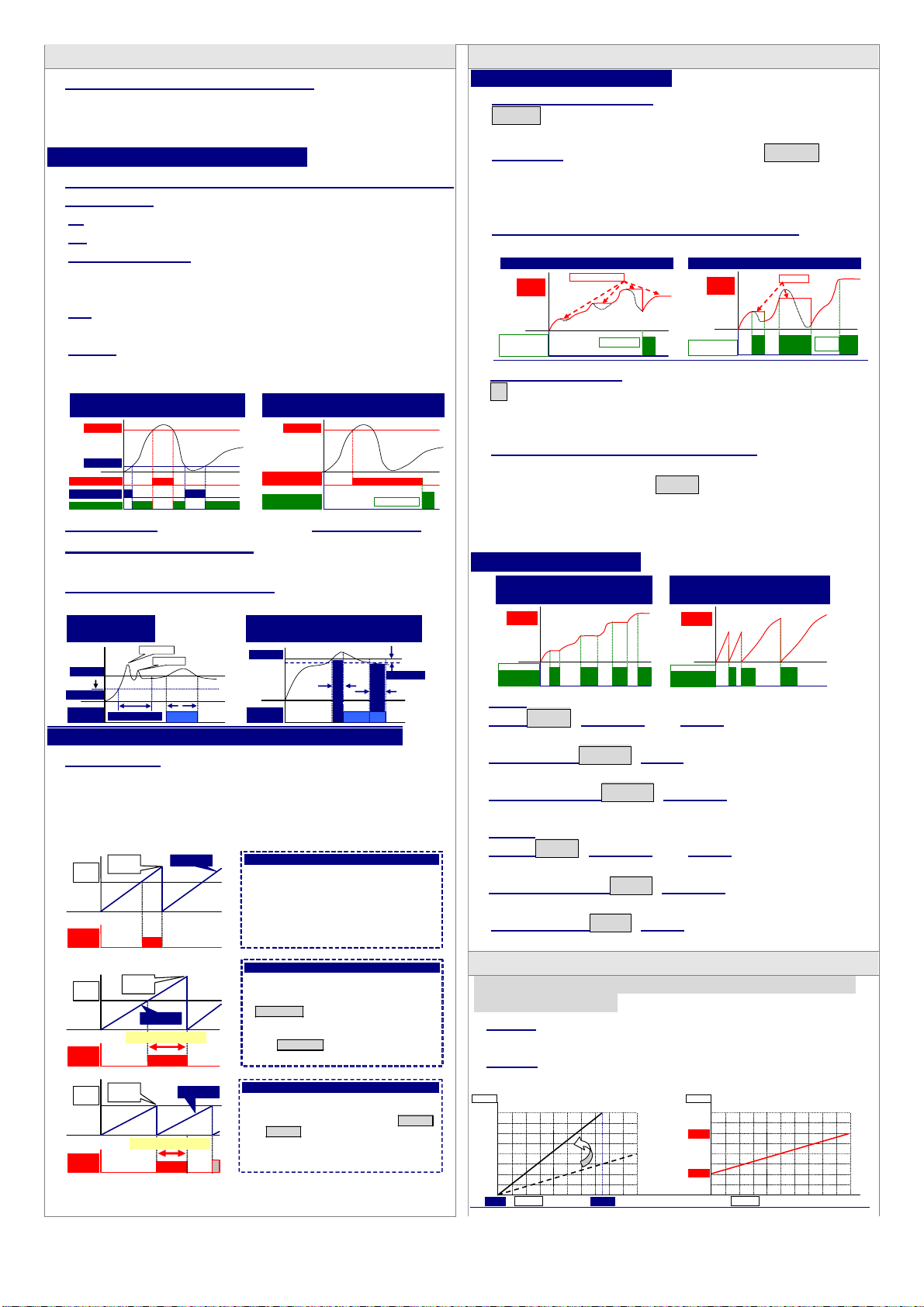
Relative to Totalizer / Batch / Batch Counter
N/C/R Mode
The 3 mode are very useful idea to control the
totalizer and batch. The relay energized condition is
according to not only energized level, but also time
and reset for totalizer, batch and batch counter.
N MODE:
When the condition of Set Point is met:
1. the relay will be energized;
2. The totalizer will run as same as
usual; until manual reset by front key
or by rear terminal, the totalizer will
be reseted to “0” and the relay will be
de-energized.
Set
Point
Relay
Output ON
Totalizer
Manual
Reset
R MODE:
When the condition of Set Point is met:
1. The relay will be energized; until the
time is over Relay output time
rY.1(2).ot(Relay1(2) output time).
2. The totalizer will run as same as
usual; until the time is over Relay output
time rY.1(2).ot(Relay1(2) output
time),The totalizer will be reset to “0”.
ON
Auto
Reset
Relay output Time
Totalizer
Set
Point
Relay
Output
C MODE:
When the condition of Set Point is met:
1. The relay will be energized; until the
time is over Relay output time rY.1.ot
or rY.2.ot.
2. The totalizer will be reset to “0”, then
counts-up from “0”.
ON
Relay
Output
Set
Point
Auto
Reset Totalize
Relay output Time
Period of Relay on:
0:00.0~9(Minutes):59.9(Second)
Fo
Immediate
alue(PV)
Relative PV or Tare: The E.C.I. can be set to be
Rel.Pv(Relative PV) function. When the E.C.I. is
closed, the reading will show the differential value.
PV Hold: The E.C.I. can be set to be Pv.HLd(PV
Hold) function. The display will be hold when the
E.C.I. is closed, until the E.C.I. is to be open. Please
refer to the below figure.
Reset for Maximum or Minimum Hold: Please
refer to the below figure.
Max. ( Mini.) Hold & Reset PV Hold & Reset
Present
Value
Reset Data Hold
by E.C.I. ON
Level
ON
ON
Reset the Max.(or
Mini.) Hold by
E.C.I. or Front Key
ON
Level Trigger
Maximum Hold
PV Hold
Present
Value
DI(Digital Input): The E.C.I can be set to be
DI(Digital Input) function, when the meter building in
RS485 port. The computer is easier to get a switch
status through the meter as like as DI of PLC.
Reset for Relay Energized Latch: If relay
energized mode was set to be Energized hold, the
E.C.I. can be set to be rY.rSt(Reset Relay function).
When the PV meets the condition of relay
energizing, the relay will be hold until the E.C.I. is
closed.
For Totalizer / Batch)
Gate for Energy / Batch
Energy Reset for Energy / Batch
Energy
Energy
/ Batch
Gate by E.C.I.
or Front Key
O
N
Level Trigge
ON ON ON Reset by E.C.I.
or Front Key
O
N
Ed
e Tri
e
ON ON
Energy
/ Batch
Gate
Gate GAtE: Totalizer and Batch will be stop to
count, when E.C.I. Iis close.
Batch Gate bt.GtE: Batch will be stop to count,
when E.C.I. Iis close.
Totalizer Gate tL.GtE: Totalizer will be stop to
count, when E.C.I. Iis close.
Reset
ResetrESEt: Totalizer and Batch will be reset to “0”,
when E.C.I. Iis close.
Totalizer ResettL.rSt: Totalizer will be reset to “0”,
when E.C.I. Iis close.
Batch Resetbt.rSt: Batch will be reset to “0”, when
E.C.I. Iis close.
■ ANALOGUE OUTPUT FUNCTIONS
Relative to immediate value(PV), totalizer, batch or batch
count programmable.
Ao.LS: Setting range: -19999~+29999;
Analogue Output Low relative Low Scale
Ao.HS: Setting range: -19999~+29999;
Analogue Output relative High Scale
SCALE
Default: Ai.Lo: 0%, Ai.Hi: 100%; Lo.SC: 0.00, Hi.SC: 100.00
Chan
e to Ai.Lo: 0%, Ai.Hi: 75%; Lo.SC: 0.00, Hi.SC: 199.99
0.00
199.99
100.00
0.00%
100.00%
50.00%
INPUT
75.00%
0.00% 100.00%
50.00%
OUTPUT
199.99
100.00
0.00
Setted Scaling: Lo.SC: 0.00, Hi.SC: 199.99;
Desired Output: Ao.Lo: 50.00
PV
, Ao.Hi: 150.00
PV
150.00
SCALE