Aeris XR2 Manuale utente

XR2
DIVE COMPUTER
OPERATING MANUAL

2
LIMITED TWO-YEAR WARRANTY
For details, refer to the Product Warranty Registration Card provided.
COPYRIGHT NOTICE
This Operating Manual is copyrighted, all rights are reserved. It may not, in hole or in part, be copied, pho-
tocopied, reproduced, translated, or reduced to any electronic medium or machine readable form ithout prior
consent in riting from AERIS / 2002 Design.
XR2 Operating Manual, Doc. No. 12-7195
© 2002 Design, 2005
San Leandro, CA USA 94577
TRADEMARK NOTICE
AERIS, the AERIS logo, XR2, and the XR2 logo are all registered and unregistered trademarks of AERIS.
Those Trademarks Registered are Registered in the U.S. Patent and Trademark Office. All rights are reserved.
PATENT NOTICE
U.S. Patents have been issued, or applied for, to protect the follo ing design features:
Dive Time Remaining (U.S. Patent no. 4,586,136), Data Sensing and Processing Device (U.S. Patent no.
4,882,678), and Ascent Rate Indicator (U.S. Patent no. 5,156,055). User Setable Display (U.S. Patent no.
5,845,235) is o ned by Suunto Oy (Finland).
DECOMPRESSION MODEL
The programs ithin the XR2 simulate the absorption of nitrogen into the body by using a mathematical
model. This model is merely a ay to apply a limited set of data to a large range of experiences. The XR2
dive computer model is based upon the latest research and experiments in decompression theory. Still, using
the XR2, just as using the U.S. Navy (or other) No Decompression Ta les, is no guarantee of avoiding de-
compression sickness, i.e. the ends. Every divers physiology is different, and can even vary from day to
day. No machine can predict ho your body ill react to a particular dive profile.

3
CONTENTS
WARRANTY ................................................................................................................................................................. 2
NOTICES ..................................................................................................................................................................... 2
DECOMPRESSION MODEL ....................................................................................................................................... 2
FULL LCD LAYOUT .................................................................................................................................................... 6
FEATURES AND DISPLAYS ............................................................................................. 7
CONTROL BUTTONS ................................................................................................................................................. 9
BAR GRAPHS ............................................................................................................................................................. 9
Nitrogen Bar Graph ................................................................................................................................................ 9
Oxygen (O2) Bar Graph ....................................................................................................................................... 10
Variable Ascent Rate ndicator ............................................................................................................................. 10
INFORMATIONAL DISPLAYS ................................................................................................................................... 11
Depth Displays ...................................................................................................................................................... 11
Time and Date Displays ....................................................................................................................................... 11
Temperature Display ............................................................................................................................................. 12
AUDIBLE ALARM ...................................................................................................................................................... 13
LED WARNING INDICATOR ..................................................................................................................................... 14
BACKLIGHT .............................................................................................................................................................. 14
POWER SUPPLY ...................................................................................................................................................... 15
Battery ndicator ................................................................................................................................................... 15
Low Battery Condition .......................................................................................................................................... 16
FO2 MODE ................................................................................................................................................................ 17
FO2 50% Default .................................................................................................................................................. 18
DI E TIME REMAINING ........................................................................................................................................... 19
ACTIVATION AND SETUP .............................................................................................. 21
ACTI ATION .............................................................................................................................................................. 22
SURFACE MODE ...................................................................................................................................................... 23
SET MODES .............................................................................................................................................................. 24
ENTER NG SETT NGS -SET MODE #1 .............................................................................................................. 25
ENTER NG SETT NGS -SET MODE #2 .............................................................................................................. 29

4
RESET (CLEAR) FEATURE ........................................................................................... 42
PRE DIVE PLAN MODE ................................................................................................. 43
DI E PLANNER ......................................................................................................................................................... 44
DIVE MODES .................................................................................................................. 47
DI E MODE BAR GRAPHS ...................................................................................................................................... 48
CONTROL OF DISPLAYS ......................................................................................................................................... 48
NO DECOMPRESSION DI E MODE ....................................................................................................................... 49
DECOMPRESSION DI E MODE .............................................................................................................................. 52
IOLATION MODES .................................................................................................................................................. 55
Conditional Violation ............................................................................................................................................. 56
Delayed Violation 1/2/3 ......................................................................................................................................... 57
mmediate Violation Mode and Violation Gauge Mode ........................................................................................ 58
HIGH PO2 .................................................................................................................................................................. 60
HIGH OXYGEN ACCUMULATION ............................................................................................................................ 61
USER SET DIGITAL GAUGE MODE ........................................................................................................................ 63
POST DIVE MODES ....................................................................................................... 65
POST DI E SURFACE MODE .................................................................................................................................. 66
TRANSITION PERIOD .............................................................................................................................................. 66
AFTER THE TRANSITION PERIOD (THE FIRST 2 HOURS) .................................................................................. 68
To access the Dive Planner (Plan Mode) ............................................................................................................. 68
To access the Time to Fly Countdown ................................................................................................................. 69
To access the Time to Desaturate Countdown .................................................................................................... 70
LOG MODE .......................................................................................................................................................... 70
AFTER THE FIRST 2 HOURS .................................................................................................................................. 73
WET ACTI ATION CONTACTS ................................................................................................................................73
DOWNLOADING DATA TO A PC .............................................................................................................................. 73
CONTENTS (con inued)
5
SIMULATOR (DEMO) MODE .......................................................................................... 75
CARE, MAINTENANCE, AND SERVICE ........................................................................ 81
CARE AND CLEANING ............................................................................................................................................. 82
INSPECTIONS AND SER ICE ................................................................................................................................. 83
BATTERY REPLACEMENT ...................................................................................................................................... 84
REFERENCE ................................................................................................................... 89
ALTITUDE SAMPLING/COMPENSATION ............................................................................................................... 90
SPECIFICATIONS ........................................................................................................... 92
SERVICE RECORD ........................................................................................................ 99
CONTENTS (con inued)
Pay special a en ion o i ems marked wi h his Warning symbol.
6
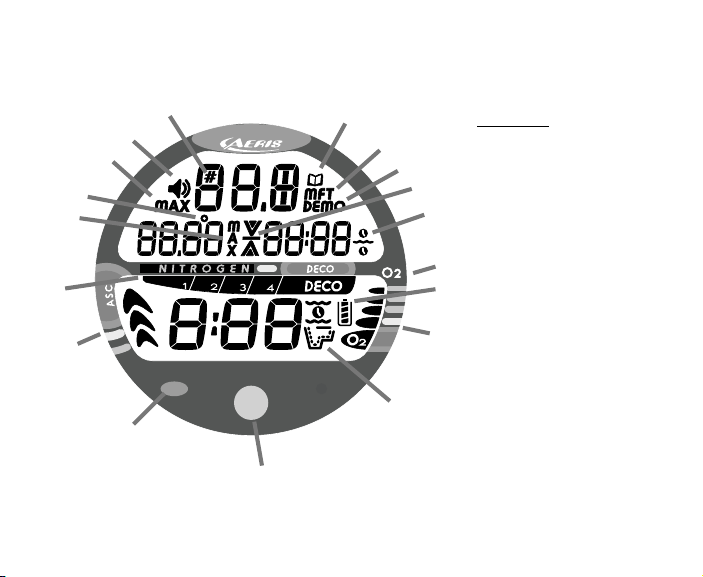
FULL LCD LAYOUT
Components:
a. Advance (Front) Button
b. Red Alarm Light
c. VAR
d. NiBG
e. con - Max Depth (Dive)
f. con - Temperature
g. con - Max Depth (Log)
h. con - Set Alarm
i. con - Dive Number
j. con - Log Mode
k. con - Depth Units
l. con - Demo Mode
m. con - Ascend Arrow
con - Deco Ceiling Bar
con - Descend Arrow
n. con - Time
o. Select (Side) Button
p. con - Battery Status
q. O2BG
r. con - Operating Mode
a
b
c
d
e
f
g
h
ij
k
l
m
n
o
p
q
r
7
FEATURES and DISPLAYS
WARNING: Prior o diving wi h he XR2, you mus also read and
unders and he AERIS Dive Compu er Safe y & Reference Manual,
Doc. No. 12-7203, which provides Impor an Warnings and Safe y
Recommenda ions as well as general produc informa ion.

8
WELCOME TO AERIS !
AND
THANK YOU FOR CHOOSING THE XR2 !
Your XR2 presents the information that you need before, during, and after your air (or nitrox)
dives using a combination of easy to read displays and identification icons. It can also be set to
operate simply as a digital depth gauge timer. This instructional guide is intended to help you be-
come familiar with the functions and features available and show you examples of displays that
you could expect to see in the various operational modes. Relax and read through the complete
owner's guide.
Remember that the rules you learned in your basic scuba certification course(s) still apply to the
diving you will do while using a dive computer - some will become even more important. Tech-
nology is no substitute for common sense, and a dive computer only provides the person using it
with data, not the knowledge to use it.
Since the XR2 can be used when diving with either Air or Nitrox, the term Breathing Gas is used
in this manual.
Breathing Gas is the gaseous mixture breathed during a dive.
Air is a breathing gas that contains approximately 21% oxygen and 79% nitrogen (nature's
common nitrogen-oxygen mixture).
Nitrox is a nitrogen-oxygen breathing gas that contains a higher fraction of oxygen (22 to 50%)
than air.

9
CONTROL BUTTONS
The two Control Buttons allow you to select display options, access specific information when
you want to see it, and activate the Backlight.
The Front button is named Advance (Fig. 1a) and the Side button Select (Fig. 1b).
BAR GRAPHS
Ni rogen Bar Graph
The Nitrogen Bar Graph (Fig. 1c) represents tissue loading of nitrogen, showing your relative No
Decompression or Decompression status. As your Depth and Elapsed Dive Time increase, seg-
ments will add to the Graph, and as you Ascend to shallower depths, the Bar Graph will begin to
recede, indicating that additional No Decompression Time is allowed for multilevel diving.
The Nitrogen Bar Graph monitors 12 different nitrogen compart-
ments simultaneously and displays the one that is in control of your
dive. It is divided into a gray No Decompression (normal) zone, a
yellow Caution zone (also No Decompression), and a red Decom-
pression (danger) zone.
While you cannot provide a guarantee against the occurrence of de-
compression sickness, you may choose your own personal zone of
caution based upon age, physique, excessive weight, etc., to reduce
the statistical risk.
Fig. 1 - Buttons and NiBG
a
b
c
10
Oxygen (O2) Accumula ion Bar Graph
The O2 Bar Graph (Fig. 2a) represents Oxygen Loading, your rela-
tive oxygen tolerance dosage (OTU), showing the maximum of ei-
ther per dive accumulated Oxygen, or 24 hour period accumulated
Oxygen. As your accumulation increases during the dive, seg-
ments will add to the Bar Graph, and as loading decreases, it will
begin to recede, indicating that additional exposure is allowed.
NOTE: Displays associa ed wi h Oxygen and he
O2 Bar Graph will only appear if FO2 has been se
a a value o her han 'Air' (e.g., a numerical value).
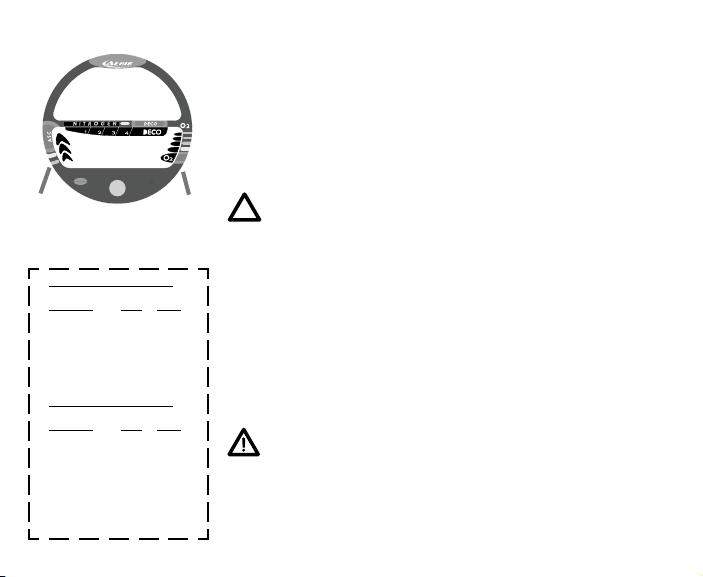
Variable Ascen Ra e Indica or
The Variable Ascent Rate Indicator (Fig. 2b) provides a visual rep-
resentation of Ascent Speed (i.e., an ascent speedometer). Gray is
a 'normal' rate, yellow a 'caution' rate, and red is 'Too Fast'. The
segments of the Variable Ascent Rate Indicator represent 2 sets of
speeds which change at a reference depth of 60 feet (18 meters).
Refer to the chart for segment values.
WARNING: A dep hs grea er han 60 fee (18
me ers), Ascen Ra es should no exceed 60 fee
per minu e (18 mpm). A dep hs of 60 fee (18
me ers) and shallower, Ascen Ra es should no
exceed 30 fee per minu e (9 me ers per minu e).
Fig. 2 - O2BG & VAR
Variable Ascent Rate ndicator
Deeper than 60 feet (18 m)
Segments Ascent Rate =
Displayed FPM MPM
0 0-20 0 - 6
1 21-30 6.5-9
2 31- 0 9.5-12
3 1-50 12.5-15
51-60 15.5-18
5 >60 >18
60 feet (18 m) & Shallower
Segments Ascent Rate =
Displayed FPM MPM
0 0-10 0 - 3
1 11-15 3.5- .5
2 16-20 5-6
3 21-25 6.5-7.5
26-30 8-9
5 >30 >9
a
b
Indice
Altri manuali Aeris Strumento subacqueo

Aeris
Aeris A300 XT Manuale utente

Aeris
Aeris ATMOS ai Manuale utente

Aeris
Aeris XR1 Manuale utente

Aeris
Aeris A300 CS Manuale utente

Aeris
Aeris Elite T3 Manuale utente

Aeris
Aeris 750GT Manuale utente

Aeris
Aeris Manta Manuale utente

Aeris
Aeris ATMOS 2 Manuale utente

Aeris
Aeris CompuMask Manuale utente

Aeris
Aeris Manta Manuale utente


