AIR SYSTEMS INTERNATIONAL SVB-E8 Manuale

OPERATING INSTRUCTIONS AND REPLACEMENT PARTS
Models: SVB-E8, SVB-E8-2, SVB-E8EC,
SVB-E8EXP, SVB-A8, AND SVB-G8
AIR SYSTEMS INTERNATIONAL, INC.
829 Juniper Crescent, Chesapeake, Va, 23320
Telephone (757) 424-3967
Toll Free 1-800-866-8100
Fax No. (757) 424-5348
www.airsystems.com.
e-mail: [email protected]
This manual must be read carefully and followed by all persons who have or will have the responsibility
for using or servicing this equipment. This equipment will perform as designed only if used according
to the instructions. Otherwise it could fail to perform as designed, causing personal injury or death.
WARNING
All ventilation procedures should comply with federal, state, and local regulations. Air quality should be tested prior to
ventilating a con ned space. A purge chart is provided on our website, www.airsystems.com, help assist in estimating the
approximate time needed to ventilate con ned spaces. Air quality should be tested continuously during con ned space
occupancy to ensure a stable atmosphere and worker safety because atmospheric conditions can change rapidly. Addi-
tional procedures and recommendations are available from federal, state, and local agencies. DO NOT operate these fan
unit in a vertical position or with the ange or guards removed.
Note: If volatile or explosive vapors are suspected, use Air Systems’ explosion proof electric blower, Model No. SVB-
E8EXP, explosion proof in-line fan, Model No. SVF-10EXP, explosion proof contractors fan, Model No. CVF-8EXP or Air
Systems’ intrinsically safe pneumatic blower, Model No. SVB-A8.
Note: For con ned space ventilation in non-hazardous locations, use Air Systems’ con ned space ventilation kit, Model
SV-CUP. For hazardous locations use ventilation kit, Model SV-CUPCND along with one of the above explosion proof
blowers or fans.
SAFETY PRECAUTIONS
READ AND FOLLOW ALL INSTRUCTIONS BELOW
WARNING
Fan and blower models with the “EX” or “X” designation are the
only models approved for use in hazardous locations. These
models are NOT approved for use in mines.
2
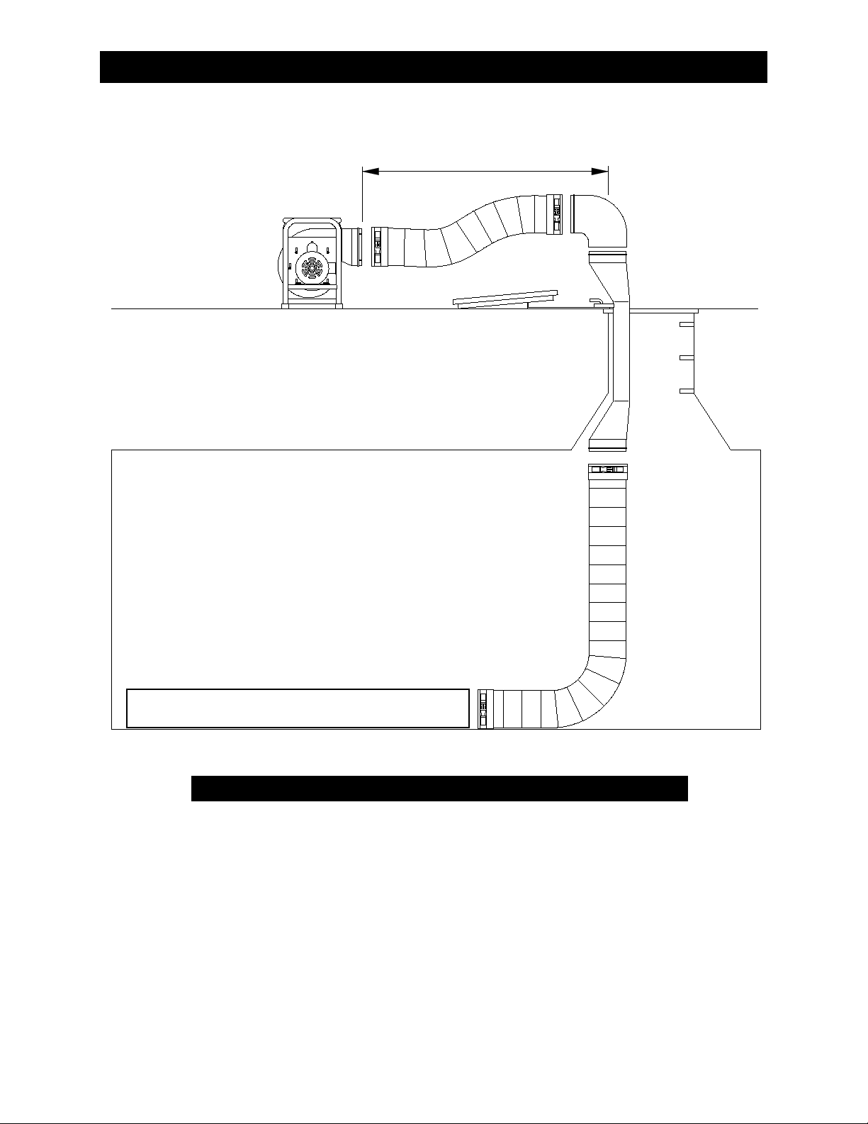
Typical Saddle Vent® Setup Procedure
Place fan or blower a minimum of
5 ft. (1.6m) from manhole opening
Blower or Fan
90° Elbow
Manhole
Opening
Manhole Lid
Universal Mount
Saddle Vent®
Select a blower or fan based on environmental
conditions and the size of the con ned space.
For information or guidance in selecting the
proper set-up, please contact Customer Service.
STEP 1) Install 6 ft. (1.8m) duct on blower or fan
STEP 2) Install 90° elbow on top of Saddle Vent®
STEP 3) Install duct on bottom of Saddle Vent®
STEP 4) Install universal mount on Saddle Vent® and
set in place with manhole lid for support
STEP 5) Install duct from blower to 90° elbow
STEP 6) Turn on blower or fan
Warning: For explosive environments,
follow ANSI/API 2015 and 2016 procedures
The Saddle Vent® is a registered trademark of Air Systems International, Inc.
The Conductive Saddle Vent® is covered by U.S. and Foreign Patents
WARNING: HAZARDOUS LOCATION OPERATIONS
Use an explosion-proof or intrinsically safe blower or fan,
conductive ducting, and The Conductive Saddle Vent® System.
Attach all grounding wires and assure a complete circuit to the
blower or fan in order to remove static charges.
The Saddle Vent® Ventilation System
3

STEP 1)
Place blower in a clean fresh air environment. Set blower a minimum of 5 ft. from the man-
hole opening. Note: Inspect blower for damaged or worn parts. Inspect all ducting
and couplings for possible air leaks prior to blower operation.
Note: Air quality of the conned space should be tested prior to ventilation. If air
quality of the conned space is unacceptable, consult a trained professional.
STEP 2)
Install duct cuff to exhaust ange and tighten cinch strap. Keep bends and kinks in ducting
to a minimum to maximize air ow.
STEP 3)
Connect to 120 VAC/60 Hz/15 amp service. All standard electric blowers listed are
supplied with a GFI (Ground Fault Interrupter) plug per the 1996 NEC code require-
ment: Section 305-6.
Note: If an extension cord is required, the minimum recommended size is 12
AWG (maximum 100 ft.). For further information; refer to the National Electric
Code Tables, Article 400. The use of generators is not recommended unless
they are of sufcient output capacity. Some generator’s output current will not
allow the use of GFI plugs. A standard 3 prong plug would need to be installed
instead of the GFI.
STEP 4)
Push the “ON/OFF” switch, located on the GFI plug, to the “ON” position. The unit is
now operational.
4
General Setup & Operation
Models: SVB-E8EC, SVB-E8, & SVB-E8-2

PROBLEM POSSIBLE CAUSE SOLUTION
Excessive vibration
Air intake blocked Turn blower off and clear debris from intake.
Possible internal damage Turn blower off and inspect fan blades, shaft, and
housing for debris, damage, and loose screws.
Possible external damage Turn blower off and inspect blower housing and
frame.
Blower will not start Circuit breaker trips Wattage output of power source insufcient*
Extension cord improperly sized
Faulty wall outlet Test voltage with meter.
* Note: The use of generators is not recommended unless they are of sufcient output capacity.
Model SVB-E8EC SVB-E8 SVB-E8-2
Motor
1/2 HP (.37 kw) electric,
115 VAC/60 Hz, single speed,
GFI cord installed
3/4 HP (.56 kw) electric,
115 VAC/60 Hz, single
speed, GFI cord installed
3/4 HP (.56 kw) electric,
115 VAC/60 Hz, two Speed, GFI
cord installed
Full Load
Amperage 8.0 amps 10.8 amps 11.2 amps
Flow Rates
Free air: 1390 CFM
25 ft. duct with one 90° bend:
931 CFM
25 ft. duct with two 90° bends:
779 CFM
Free air: 1570 CFM
25 ft. duct with one 90°
bend: 1047 CFM
25 ft. duct with two 90°
bends: 873 CFM
Free air: 750/1570 CFM low/high
25 ft. duct with one 90° bend: 490
CFM Low/ 1047 CFM High
25 ft. duct with two 90° bends:
425/873 CFM low/high
Inlet/Outlet Size 8” Diameter 8” Diameter 8” Diameter
Noise Level 76 dba @ 3 ft. 76 dba @ 3 ft. 76 dba @ 3 ft.
Weight 37 lbs. 53 lbs. 58 lbs.
5
Troubleshooting
Specications

SVB-E8 AND SVB-E8-2 SVB-E8EC
C US
®
ITEM # DESCRIPTION SVB-E8 SVB-E8-2 SVB-E8EC
1 MOTOR MTR002 MTR021 MTR040
2GFI POWER CORD ELCB013 ELCB013 ELCB013
3INTAKE/DISCHARGE GUARD SVB-GRD SVB-GRD SVB-GRD
4 RUBBER FOOT HDWR025 HDWR025 HDWR025
5 WHEEL HOUSING SVB-WH SVB-WH SVB-WH
6
System Components

STEP 1)
Place blower in a clean fresh air environment. Set blower a minimum of 5 ft. from the man-
hole opening. Note: Inspect blower for damaged or worn parts. Inspect all ducting
and couplings for possible air leaks prior to blower operation.
Note: Air quality of the conned space should be tested prior to ventilation. If air
quality of the conned space is unacceptable, consult a trained professional.
STEP 2)
Install duct cuff to exhaust ange and tighten cinch strap. Keep bends and kinks in ducting
to a minimum to maximize air ow.
NOTE: The use of conductive ducting is recommended when operating in potentially
explosive environments. Assure that the blower is properly grounded before oper-
ating and the ground wire in the conductive ducting is attached to the blower and
Saddle Vent®, if used.
Grounding lug provided for
ground wire attachment from
conductive duct.
STEP 3)
Explosion-proof models should be tted with an approved explosion-proof plug to meet Class 1, Div. 1, Groups C and D,
Class II, Div. I, Groups E, F, G specications. The plug should not be disconnected or connected in an explosive environ–
ment when the blower is energized.
STEP 4)
Switch the explosion-proof “ON/OFF” switch to the “ON” position. The unit is now operational.
CAUTION:
If explosive or volatile vapors are suspected or present, follow ANSI/API
procedure 2015 and 2016 for proper grounding of the blower. All static
electricity must be removed from the blower and attached ducting prior to
energizing the blower. Conductive ducting should be tested semi-annually
to assure resistance (ohms) does not exceed 300k. If sufcient resistance is
not achieved, the duct should be removed from service.
PROBLEM POSSIBLE CAUSE SOLUTION
Excessive vibration
Air intake blocked Turn blower off and clear debris from intake.
Possible internal damage Turn blower off and inspect fan blades, shaft, and
housing for debris, damage, and loose screws.
Possible external damage Turn blower off and inspect blower housing and
frame.
Blower will not start Circuit breaker trips Wattage output of power source insufcient*
Extension cord improperly sized
Faulty wall outlet Test voltage with meter.
7
Troubleshooting
General Setup & Operation
Model: SVB-E8EXP

ITEM # DESCRIPTION SVB-E8EXP
1 EXPLOSION PROOF MOTOR MTR003
2 EXPLOSION PROOF ON/OFF SWITCH ELSW028
3INTAKE/DISCHARGE GUARD SVB-GRDCND
4 RUBBER FOOT HDWR025
5 WHEEL HOUSING SVB-WH-CND
6POWER CORD (SOLD BY THE FOOT) ELCB011
7 BLOWER WHEEL (SET SCREWS - FS5/16X038) METL039
8GROUND LUG ELA051
C US
®
Model # SVB-E8EXP
Motor
3/4 HP electric, 115/208-230 VAC/60Hz , single speed,
factory wired with 25 ft. power cord, no plug, explosion proof
Class I, Div. I, Groups C, and D, Class II, Div. I, Groups E, F, G
Full Load
Amperage
12.6 amps @ 115 VAC
6.3 amps @ 208-230 VAC
Switch Type Explosion-proof
Inlet/Outlet Size 8” diameter
Flow Rate
Free air: 1570 CFM
25’ duct w/one 90° bend: 1047 CFM
25’ duct w/two 90° bends: 873 CFM
Weight 72 lbs.
Noise Level 76 dbA @ 3 ft.
WARNING
For Hazardous Environments, Always Use Air Systems’ Model SV-CUPCND, Conductive
Saddle Vent® Ventilation Kit, With An Explosion-Proof Blower
8
System Components - Model: SVB-E8EXP
Specications - Model: SVB-E8EXP

STEP 1)
Operate blower in shown position only. Place in a clean fresh air environment away from
toxic gases and dust. Set blower a minimum of 5 ft. from the manhole opening.
Note: Inspect blower for damaged or worn parts. Inspect all ducting and couplings
for possible air leaks prior to blower operation.
Note: Air quality of the conned space should be tested prior to ventilation. If air
quality of the conned space is unacceptable, consult a trained professional.
STEP 4)
Install duct cuff to exhaust ange and tighten cinch strap. Keep bends and kinks in ducting
to a minimum to maximize air ow. The use of conductive ducting is recommended
when operating in potentially explosive environments. Assure that the blower is
properly grounded before operating and that the ground wires from the conductive
ducting and Saddle Vent®, if used, are securely attached to the blower’s grounding
wire.
STEP 2)
Attach and tighten the lter/regulator and lubricator assembly. Make sure oil level in the
lubricator is at the full mark (approximately 3/4 of bowl height); add additional oil if neces-
sary. Factory recommended oil is #F44200 Parker tool oil,
viscosity 100 or higher, mineral oil base, (Sunvis #932 or equivalant).
STEP 3)
Secure a primary air source with a ow capacity of 10–100cfm and a pressure range of 10
–100psi. Attach a minimum 1/2” I.D hose to the inlet tting. Note: Maximum inlet pres–
sure should not exceed 150psi (10 bar).
CAUTION:
If explosive or volatile vapors are suspected or present,
follow ANSI/API procedure 2015 and 2016 for proper
grounding of the blower. All static electricity must be
removed from the blower and attached ducting prior to
energizing the blower. Conductive ducting should be
tested semi-annually to assure resistance (ohms) does not
exceed 300k. If sufcient resistance is not achieved, the
duct should be removed from service.
9
General Setup & Operation
Model: SVB-A8
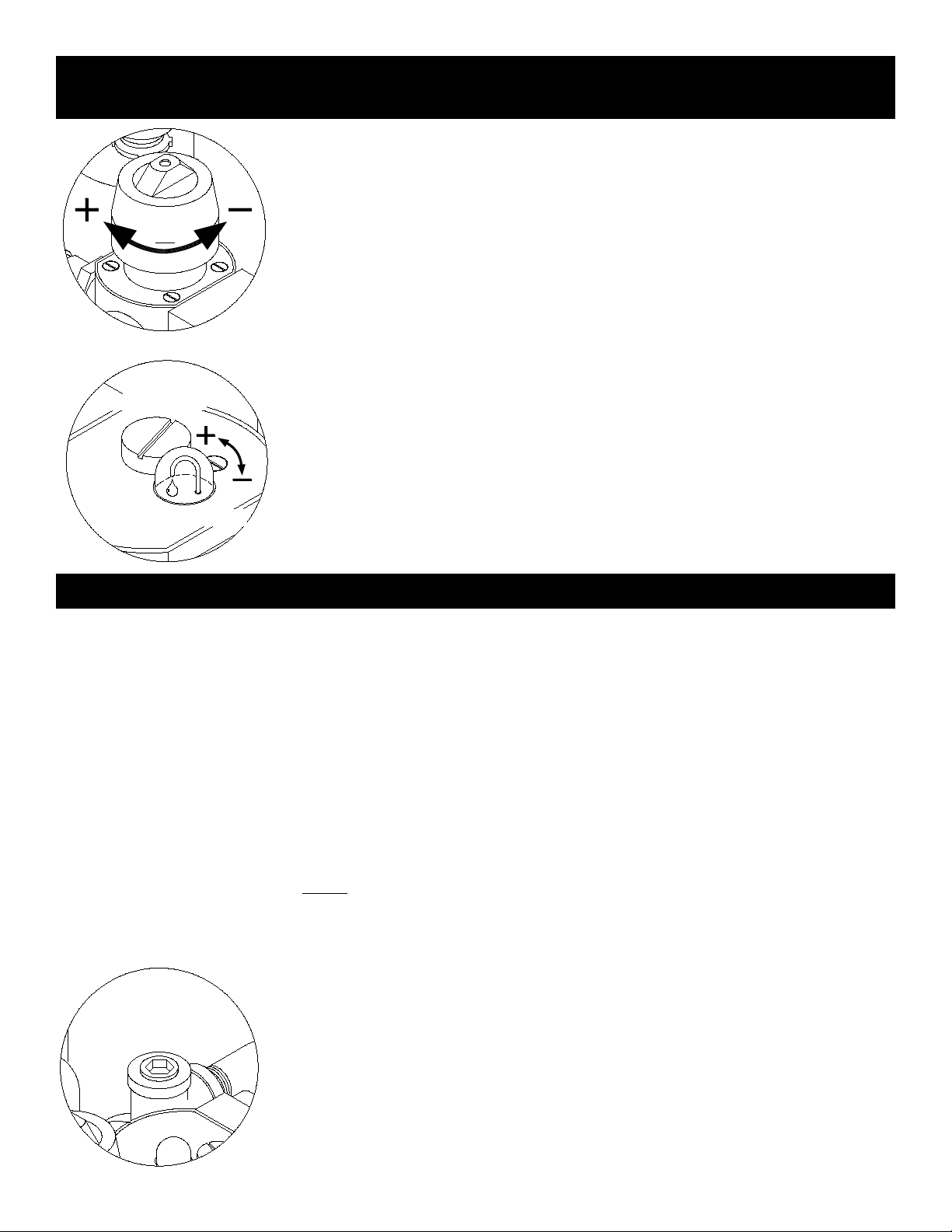
STEP 5)
Adjust pressure regulator clockwise to increase, counterclockwise to decrease motor
speed. This adjustment will increase or decrease the air ow.
Note: Available air pressure (psi) and volume (cfm) will determine blower
performance.
STEP 6)
The proper amount of oil mist has already been factory preset. However, depending on
the viscosity of the oil being used, slight adjustments may be necessary. With the blow-
er running, the proper oil mist should be one drop/min. The oil mist adjustment screw is
located next to the oil ll cap. Turn this screw clockwise to decrease or counterclockwise
to increase oil ow.
Note: Approximately 1 drop per minute can be achieved by turning the adjust-
ment screw fully clockwise, then counterclockwise 1 1/2 turns.
SIGHT GLASS
OIL FILL CAP
Keep blower motor dry and free from contaminants and dust.
Check periodically to ensure moving parts are free from obstructions.
Change lter (Part# WL040B) located in regulator after approximately 300–500 hours.
Factory recommended oil is SAE #10 non-detergent automotive engine oil or lighter. (Petroleum based only,
do not use synthetic oils)
Clean mufer assembly every 100–300 hours with safety solvent (Part #BAC–1001).
Flush air motor every 100 hours with safety solvent (#BAC–1001) through maintenance port (see below).
Remove air exhaust lter before ushing and reinstall after several minutes of running unit. Flush unit
after every 200 hours or after storing for long periods.
AIR MOTOR FLUSHING PROCEDURE
Use Air Systems’ Part #BAC-1001 safety solvent.
Do not use a ammable solvent or a solvent with a
toxicity rating of 500ppm or greater to ush the unit.
Note: Eye protection should be worn when ushing the unit.
STEP 1)
To ush the motor, turn blower off and remove exhaust lter element.
STEP 2)
Open the maintenance port. Spray 1-2 ounces of safety solvent into the maintenance port.
Close the maintenance port. Run the blower in an open area away from sparks and ames
for a minimum of ve minutes before reinstalling the exhaust lter.
10
General Setup & Operation
Model: SVB-A8
Maintenance
Questo manuale è adatto per i seguenti modelli
5
Indice


