Akw P12 Manuale utente

Please read all instructions before installation and leave this document with the end user for future reference as
it contains important warranty information
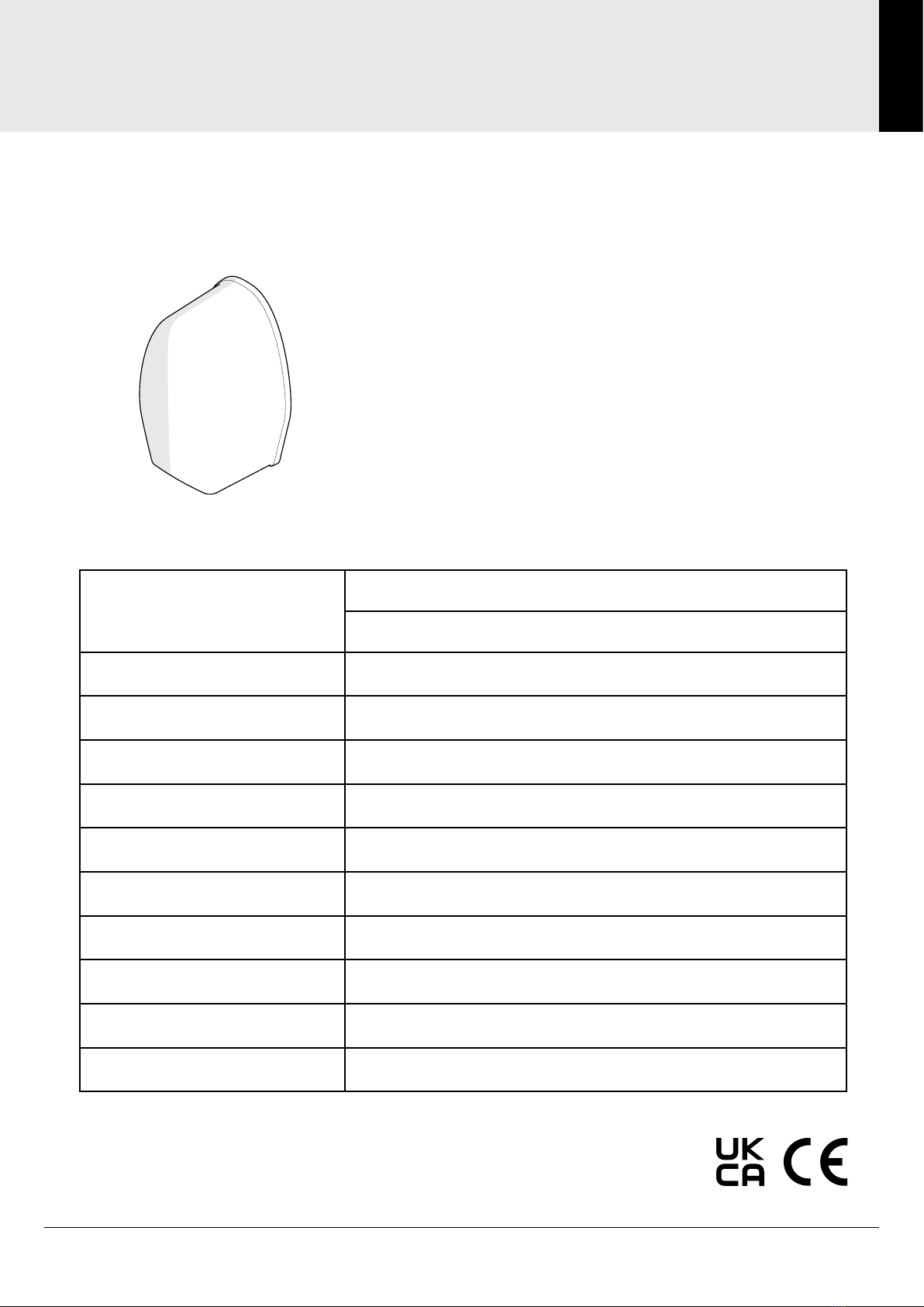
P12 Shower Waste Pump
INSTALLATION MANUAL

General: 01905 823 298 | www.akw-ltd.co.uk2
2
TABLE OF CONTENTS
Table of Contents
Specification .........................................................................................................................................................................3
Dimensions............................................................................................................................................................................4
Main Components................................................................................................................................................................5
Plumbing Zone......................................................................................................................................................................6
Preparing the Pump .............................................................................................................................................................7
Plumbing Connections .................................................................................................................................................. 8 - 9
Setting Flow Direction .......................................................................................................................................................10
Electrical Installation..........................................................................................................................................................11
Commissioning Checks ....................................................................................................................................................12
Troubleshooting..........................................................................................................................................................13 - 14
Notes.....................................................................................................................................................................................15
Contact Us ...........................................................................................................................................................................16
Technical Support: 01905 560 219 3Order: 01905 823 299 |orders.akw-ltd.co.uk
3
SPECIFICATION
Specication
P12 Shower Waste Pump
Specification
Shower Compatibility
Electric Shower
Mixer Shower
Maximum Capacity 12 lpm
Ingress Protection IPX4
Inlet Connectors 22 mm
Outlet Connectors 22 mm
Max. Outlet head 2 m
Max. Inlet lift 350 mm
Variable Speed Yes (with P12D Controller)
Compatible Wastes 22 mm Outlet
Inlet/outlet direction Selectable
Supply 24v DC
General: 01905 823 298 | www.akw-ltd.co.uk4
4
DIMENSIONS
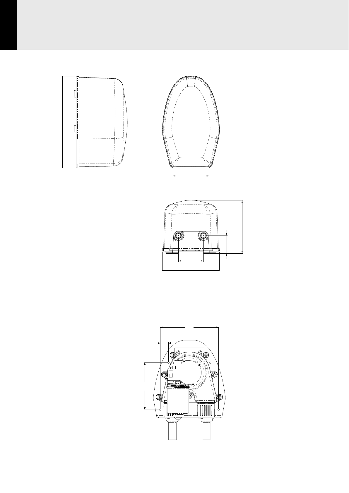
Dimensions
133.2
209.5
92.0
66.0
196.2
337.3
Mounting Dimensions
160
23
129

Technical Support: 01905 560 219 5Order: 01905 823 299 |orders.akw-ltd.co.uk
5
MAIN COMPONENTS
Main Components
Conrm you have all the correct parts required. Ensure the volume of water from the shower does not exceed
the pumps drainage capacity. Note: Increased Head/Lift conditions will affect the pump’s performance.
Box Contents
Main Components
Pump Terminals
Latch
Cover
Pump
Wall Plate
Assembly
Inlet and Outlet
Connections
Wall Plate
Pump Motor
P12 Flexible Installation Kit -
Standard (see page 8)
X1 FS-X062 Flow Switch,
X2 Push-Fit Fittings
X1 Y Filter
X2 FS-X062 Flow Switch,
X4 Push-Fit Fittings
X2 Y Filter
Mixer Shower Electric Shower
OR

General: 01905 823 298 | www.akw-ltd.co.uk6
6
PLUMBING ZONE
Plumbing Zone
This product is rated IPX4 and suitable to be installed within Zone 1 or Zone 2 of a shower room only if
these instructions are fully complied with. It must not be fitted within Zone 0.
The unit must be located away from the direct line of water jets.
Zone 1 lies above Zone 0 up to a minimum of 2.25m or to the height of the fixed shower head from the
finished floor level, which ever is greater.
If the shower has no tray then zone 1 extends to 1.2m around the fixed shower head.
Zone 2 is the area extending 0.6m beyond Zone 1 and up to the same height as Zone 1.
Diagram for guidance only - please refer to BS7671 for further details.

Technical Support: 01905 560 219 7Order: 01905 823 299 |orders.akw-ltd.co.uk
7
PREPARING THE PUMP
Preparing the Pump
Preparing Pump for mounting
1) Remove cover
2) Unscrew and open bracket with a 5 mm hexagonal key, then twist pipe connectors to unlock pump
3) Remove Pump from mounting plate
Fit to a finished surface.
Pipe connections must be easily accessible and
a clearance of 100 mm around the base and
sides is recommended. Using the back plate as a
template mark the fixing holes.
Drill and plug the wall taking care there are no
hidden cables or pipes. Use all the screw fixing
positions.
Mount the backplate to the finished surface and
attach pump component. Ensure it is secure by
locking the pipe connectors, closing the bracket
and tightening the bolt.

General: 01905 823 298 | www.akw-ltd.co.uk8
8
PLUMBING CONNECTIONS
Plumbing Connections
Note: Item 1 will need cutting down to create two hoses.
Illustrations below show the waste outlet direction going from
Left to Right - to change the direction, see page 10.
P12 Flexible Installation Kit - Standard (Stock Code: 05PP21)
Installation - Tray
Installation - Former
Item No. Title Qty.
1 3 m Flexible Hose 1
2 Ø43 mm Straight Solvent
Weld Coupler ABS
1
3 22 mm Pipe 2
4 Flexible Hose Collar 1
5 Pipe Coupling Kit 1
6 Hose Clamp 20-32 mm 4
43 mm Solvent
Weld Pipe
43 mm Solvent
Weld Pipe
Waste Tray
Former
Floor
Waste
Floor
Use item 4 to protect the
exible pipe when detailing
the oor covering

Technical Support: 01905 560 219 9Order: 01905 823 299 |orders.akw-ltd.co.uk
9
PLUMBING CONNECTIONS
Plumbing Connections
350 mm max.
LIFT
2 m max.
HEAD
Shower Head
Shower Tray/Waste
MINIMISE PIPEWORK LENGTH WHEREVER POSSIBLE.
DO NOT LEAVE EXCESS PIPE COILED UP BENEATH SHOWER TRAY
OR
For best performance locate within 1m (39in) of shower and minimise the number of
lifts, bends and the length of all pipes connecting the pump to the waste outlet pipe.
Note: Increased Head/Lift conditions will affect the pump’s performance.
CAUTION
CAUTION
READ INSTRUCTIONS
BEFORE INSTALLING
THIS PRODUCT
Important: pipe connections must be easily accessed and pipework must be secured to prevent vibration and
noise.
General: 01905 823 298 | www.akw-ltd.co.uk10
10
SETTING FLOW DIRECTION
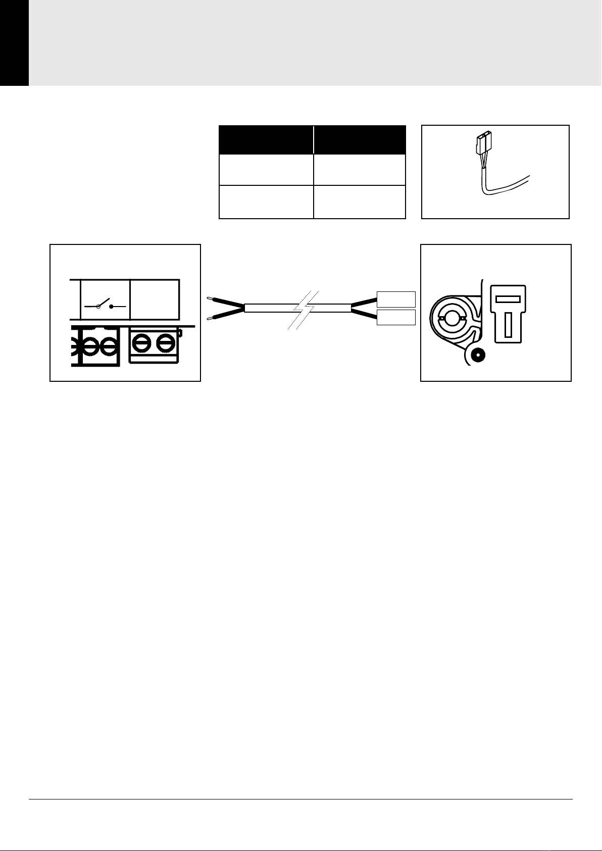
Setting Flow Direction
Select the direction using the
table shown and connect the
pump cable to the P12 using
the spades and wire end to the
control interface.
Connection Flow Direction
A to A and B to B Left to Right
B to A and A to B Right to Left
Control Interface
SENSOR 1
0 S +
SENSOR 2 AUX PUMP
0 S +
AB
P12 Pump
A
B
Pump Cable
Pump Cable
Indice
Altri manuali Akw Pompa dell'acqua


Manuali Pompa dell'acqua popolari di altre marche


Sykes AmeriPumps
Sykes AmeriPumps GP100M Guida alla risoluzione dei problemi

DUROMAX
DUROMAX XP WX Series Manuale utente

BRINKMANN PUMPS
BRINKMANN PUMPS SBF550 Manuale utente

Franklin Electric
Franklin Electric IPS Manuale utente

Xylem
Xylem e-1532 Series Manuale utente

Milton Roy
Milton Roy PRIMEROYAL Manuale utente