
ALLIANCE Dryers Manuale utente
Installation Instructions
for Dryers
Original Instructions
Keep These Instructions for Future Reference.
(If this machine changes ownership, this manual must accompany machine.)
www.alliancelaundry.com Part No. 510963R7
November 2014

Front Matter
WARNING
WARNING
FOR YOUR SAFETY, the information in this manual
must be followed to minimize the risk of fire or ex-
plosion or to prevent property damage, personal in-
jury or death.
W033
WARNING
• Do not store or use gasoline or other flammable
vapors and liquids in the vicinity of this or any
other appliance.
•WHAT TO DO IF YOU SMELL GAS:
• Do not try to light any appliance.
• Do not touch any electrical switch; do not use
any phone in your building.
• Clear the room, building or area of all occu-
pants.
• Immediately call your gas supplier from a
neighbor’s phone. Follow the gas supplier’s in-
structions.
• If you cannot reach your gas supplier, call the
fire department.
• Installation and service must be performed by a
qualified installer, service agency or the gas sup-
plier.
W052
WARNING
• Installation of unit must be performed by a quali-
fied installer.
•Install clothes dryer according to manufacturer’s
instructions and local codes.
• DO NOT install a clothes dryer with flexible plas-
tic venting materials. If flexible metal (foil type)
duct is installed, it must be of a specific type
identified by the appliance manufacturer as suita-
ble for use with clothes dryers. Refer to section
on connecting exhaust system. Flexible venting
materials are known to collapse, be easily crush-
ed, and trap lint. These conditions will obstruct
clothes dryer airflow and increase the risk of fire.
W729R1
WARNING
FOR YOUR SAFETY
Do not store or use gasoline or other flammable vapors and
liquids in the vicinity of this or any other appliance.
W053
The following information applies to the state of Massachusetts,
USA.
•This appliance can only be installed by a Massachusetts li-
censed plumber or gas fitter.
• This appliance must be installed with a 36 inch [91 cm] long
flexible gas connector.
• A "T-Handle" type gas shut-off valve must be installed in the
gas supply line to this appliance.
• This appliance must not be installed in a bedroom or bath-
room.
Front Matter
Part No. 510963R7 © Copyright, Alliance Laundry Systems LLC - DO NOT COPY or TRANSMIT 3

Table of Contents
Front Matter.......................................................................................... 3
Dimensions............................................................................................. 5
Installation............................................................................................. 7
Before You Start.............................................................................................7
Supplies..................................................................................................... 7
Order of Installation Steps............................................................................7
Position and Level the Dryer............................................................................7
Connect Dryer Exhaust System........................................................................ 9
Exhaust Direction......................................................................................10
Exhaust System.........................................................................................10
Gas Dryers - Connect Gas Supply Pipe........................................................... 12
Connect Electrical Plug (Electric Dryer Only)................................................. 13
Grounding Information.............................................................................. 13
Connecting Power Cord with Three-Wire Plug.............................................14
Connecting Power Cord with Four-Wire Plug.............................................. 16
Reverse Door, if Desired............................................................................... 17
Wipe Out Inside of Dryer.............................................................................. 19
Plug In the Dryer.......................................................................................... 19
Electric Dryer........................................................................................... 19
Gas Dryers................................................................................................19
Grounding Information.............................................................................. 20
Recheck Steps.............................................................................................. 20
Check Heat Source........................................................................................20
Electric Dryers.......................................................................................... 20
Gas Dryers................................................................................................20
Installer Checklist.................................................................................22
© Copyright 2014, Alliance Laundry Systems LLC
All rights reserved. No part of the contents of this book may be reproduced or transmitted in any form or by any means without the expressed
written consent of the publisher.
Part No. 510963R7 © Copyright, Alliance Laundry Systems LLC - DO NOT COPY or TRANSMIT 4
Dimensions
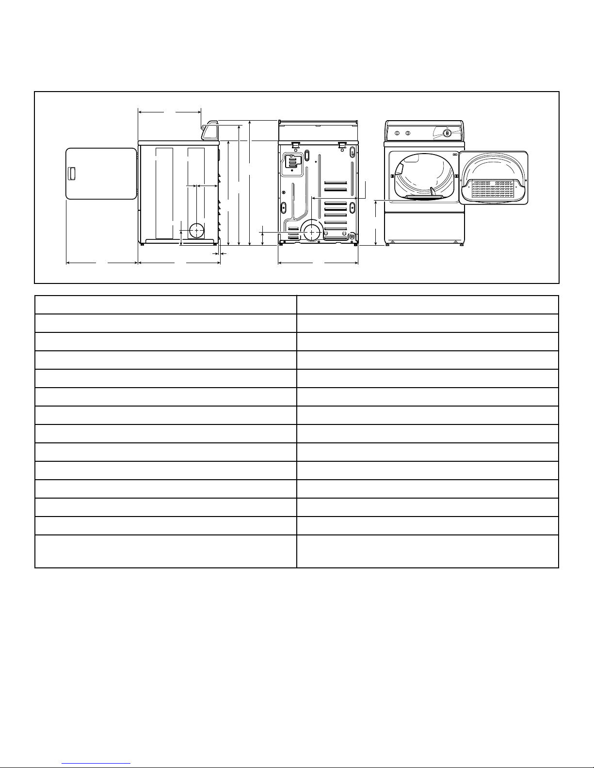
Electric Models
DRY2283N_SVG
ML
K
J
I
H
G
F
E
D
C
B
A
A 22.38 in. [569 mm]
B 8.0 in. [203 mm]
C *36 in. [914 mm]
D *40.25 in. [1022 mm]
E *43 in. [1092 mm]
F 15.4 in. [391 mm]
G * 15.44 in. [392 mm]
H 26.9 in. [683 mm]
I *4.0 in. [102 mm]
J 0.4 in. [11 mm]
K * 4.5 in. [114 mm]
L 28 in. [711 mm]
M 23.5 in. [597 mm]
NOTE: Exhaust openings are 4 inch [102 mm] metal
ducting.
* With leveling legs turned into base.
Dimensions
Part No. 510963R7 © Copyright, Alliance Laundry Systems LLC - DO NOT COPY or TRANSMIT 5
Gas Models
DRY2284N_SVG
O N
M
L
K
J
I
H
G
F
E
D
C
B
A
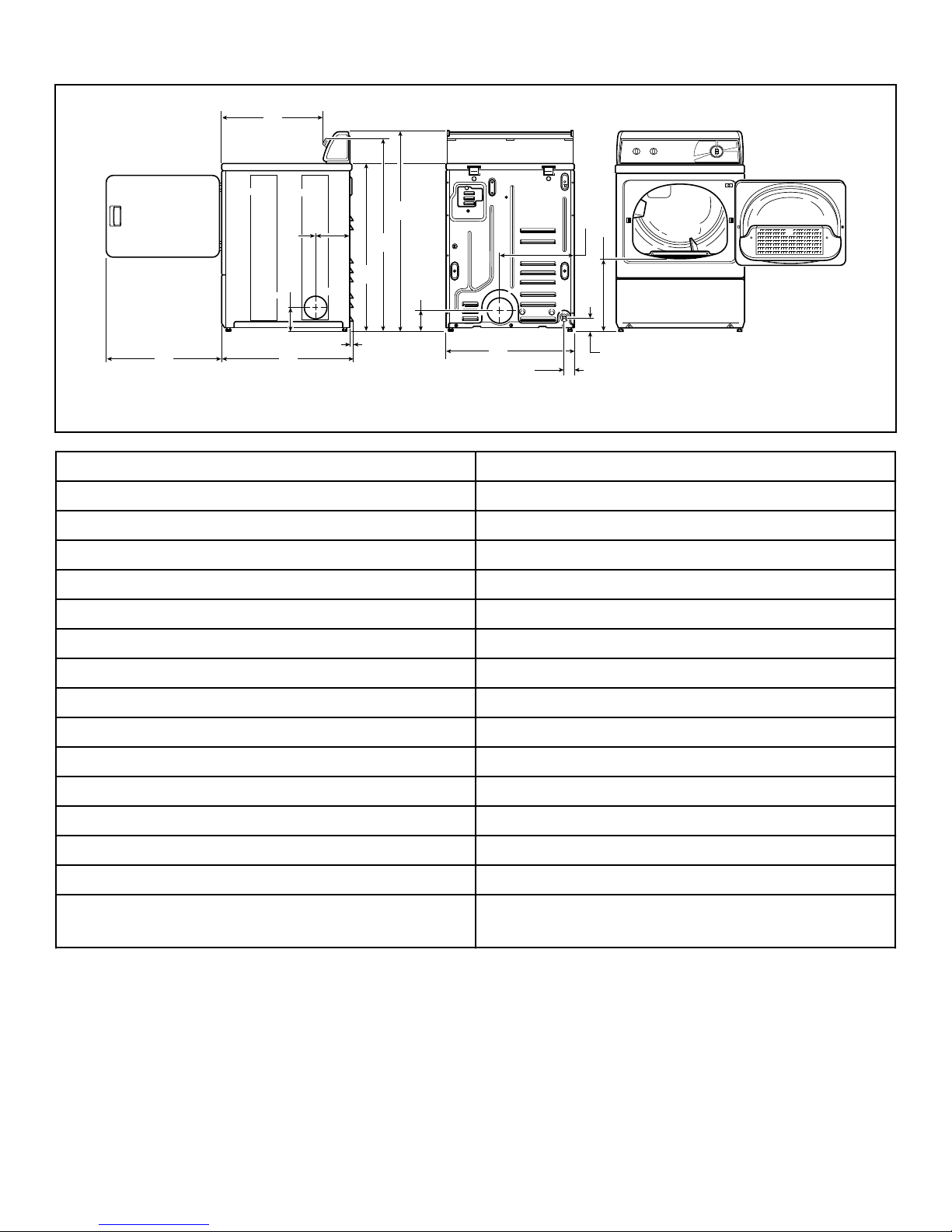
1. 3/8 in. N.P.T. Gas Connection
A 22.38 in. [569 mm]
B 8.0 in. [203 mm]
C *36 in. [914 mm]
D *40.25 in. [1022 mm]
E *43 in. [1092 mm]
F 15.4 in. [391 mm]
G *15.44 in. [392 mm]
H *2.8 in. [70 mm]
I 2.3 in. [60 mm]
J 26.9 in. [683 mm]
K *4 in. [102 mm]
L 0.4 in. [11 mm]
M *4.5 in. [114 mm]
N 28 in. [711 mm]
O 23.5 in. [597 mm]
NOTE: Exhaust openings are 4 inch [102 mm] metal
ducting.
* With leveling legs turned into base.
Dimensions
6 © Copyright, Alliance Laundry Systems LLC - DO NOT COPY or TRANSMIT Part No. 510963R7
Installation
Before You Start
Supplies
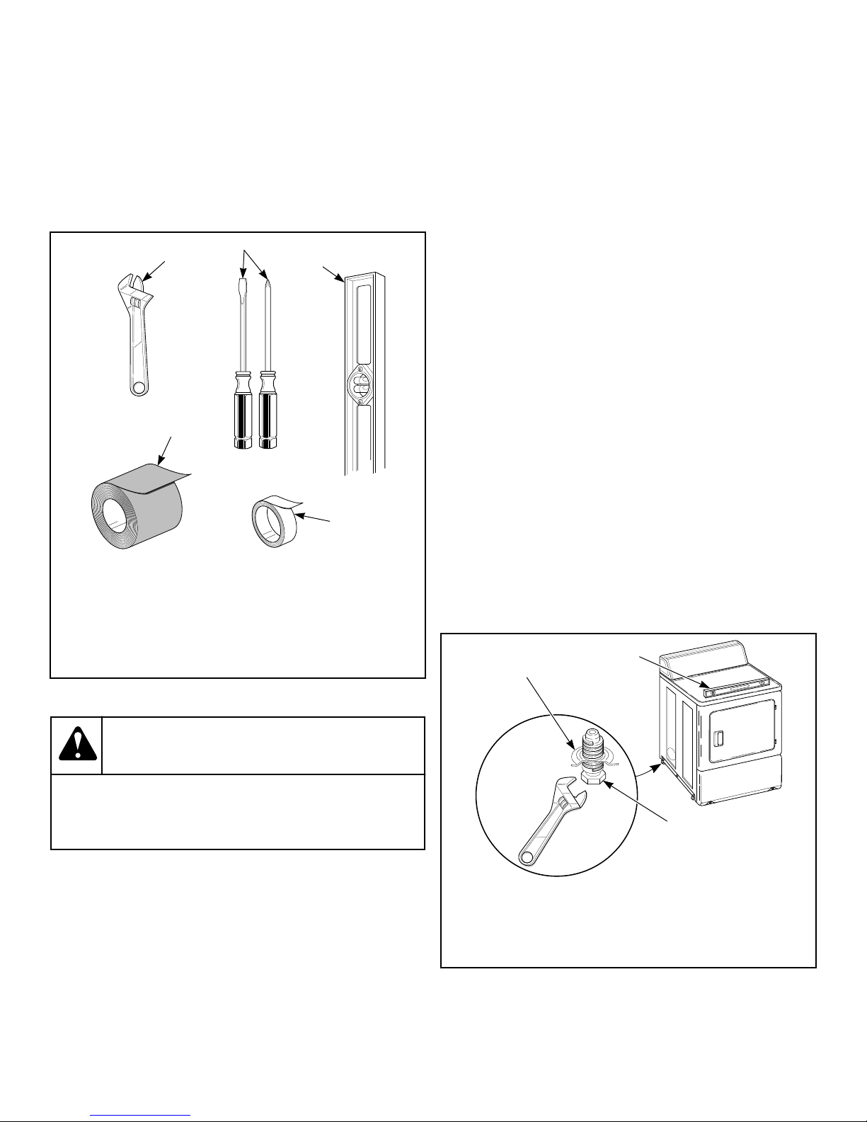
For most installations, the basic supplies you will need are:
D818I_SVG
5
4
3
2
1
1. Wrench
2. Screwdriver
3. Level
4. Duct Tape
5. Teflon Tape (Gas Models)
Figure 1
WARNING
Any disassembly requiring the use of tools must be
performed by a suitably qualified service person.
W299
Order of Installation Steps
1. Position and level the dryer.
2. Connect dryer to exhaust system.
3. For gas models only, connect the gas supply pipe. Check for
gas leaks.
4. For electric models only, connect the electrical cord.
5. Reverse the door, if desired.
6. Wipe out the inside of the dryer.
7. Plug in the dryer.
8. Recheck steps.
9. Check heat source.
Position and Level the Dryer
1. Install dryer before washer. This allows room for attaching
exhaust duct.
2. Select a location with a solid floor. Dryers installed in resi-
dential garages must be elevated 18 inches [457 mm] above
the floor.
No other fuel burning appliance should be installed in the same
closet with the dryer.
The dryer must not be installed or stored in an area where it will
be exposed to water and/or weather.
Leveling legs can be adjusted from inside the dryer with 1/4 in.
driver. All four legs must rest firmly on the floor so the weight of
the dryer is evenly distributed.
The dryer needs sufficient clearance and an adequate air supply
for proper operation and ventilation, and for easier installation
and servicing. (Minimum clearances are shown in Figure 3 ).
3. Place the dryer in position, and adjust the legs until the dryer
is level from side to side and front to back. The dryer must
not rock.
D669I_SVG
3
2
1
1. Dryer Base
2. Level
3. Leveling Leg
Figure 2
Installation
Part No. 510963R7 © Copyright, Alliance Laundry Systems LLC - DO NOT COPY or TRANSMIT 7
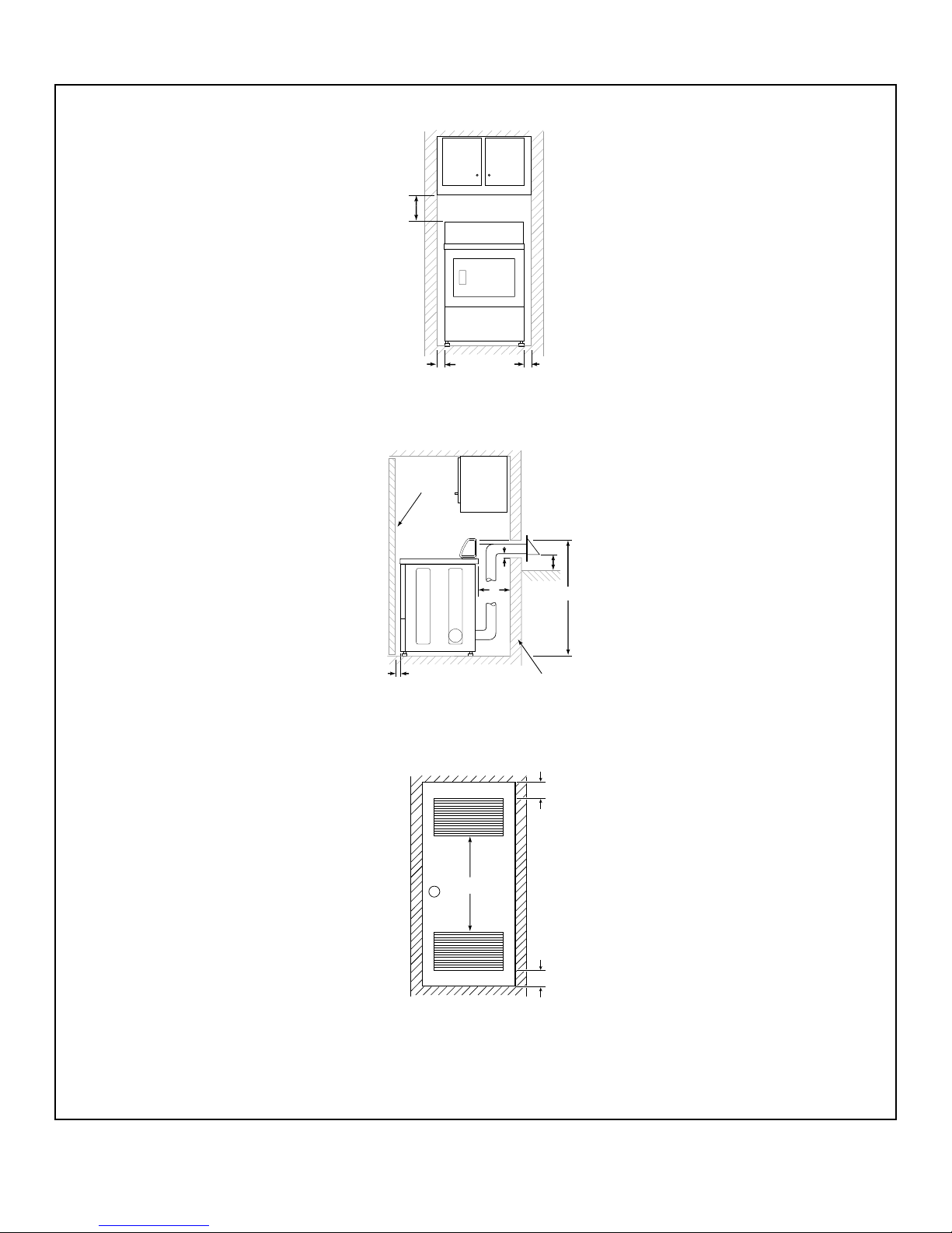
Front View (Without Closet Door)
DRY2663N_SVG
B
A A
Side View (Closet Door)
DRY2664N_SVG
1
C
A
DE
H
3
Front View (Closet Door)
DRY2637N_SVG
F
F
2 (G)
1. Closet Door
2. Centered Air Openings (G) (2 Openings minimum)
3. Outer Wall of Enclosure
Figure 3
Installation
8 © Copyright, Alliance Laundry Systems LLC - DO NOT COPY or TRANSMIT Part No. 510963R7

Area Description
Free Standing/Alcove In-
stallation Closet Installation
A* Dryer sides and rear clearance 0 in. [0 mm] 0 in. [0 mm]
B Dryer top clearance 12 in. [305 mm] 12 in. [305 mm]
C Dryer front clearance Not Applicable 2 in. [51 mm]
D Exhaust duct clearance to com-
bustible material
2 in. [51 mm] 2 in. [51 mm]
E Weather hood to ground clear-
ance
12 in. [305 mm] 12 in. [305 mm]
F Distance from floor or ceiling
to air opening edge
Not Applicable 3 in. [76 mm]
G Area of centered air openings
in closet door. Louvered door
with equivalent air openings is
acceptable. (Minimum clearan-
ces are shown.)
Not Applicable 40 sq. in./open [260 sq. cm/
open]
H For new installations, locate
top of wall vent 42 inches
[1067 mm] above floor to make
venting easier to connect.
42 in. [1067 mm] 42 in. [1067 mm]
* Rear clearance is minimum. 2 inches [51 mm] is recommended for utility connection. 6 inches
[152 mm] is recommended when venting through rear of unit.
Table 1
NOTE: For new installations, locate top of wall vent 42
inches (106.7 cm) above floor to make venting easier to
connect.
IMPORTANT: In mobile home installations, gas dryers
MUST be permanently attached to the floor at the time
of installation. Order No. 526P3 Dryer Installation Kit
(available at extra cost) for a manufactured (mobile)
home installation. Follow the instructions supplied with
the kit.
Connect Dryer Exhaust System
WARNING
To reduce the risk of fire and the accumulation of
combustion gases, DO NOT exhaust dryer air into a
window well, gas vent, chimney or enclosed, unven-
tilated area, such as an attic, wall, ceiling, crawl
space under a building or concealed space of a
building.
W045
WARNING
A clothes dryer produces combustible lint. To re-
duce the risk of fire and combustion gas accumula-
tion the dryer MUST be exahusted to the outdoors.
W116
WARNING
This gas appliance contains or produces a chemical
or chemicals which can cause death or serious ill-
ness and which are known to the State of California
to cause cancer, birth defects, or other reproductive
harm. To reduce the risk from substances in the fuel
or from fuel combustion, make sure this appliance is
installed, operated, and maintained according to the
instructions in this manual.
W115
Installation
Part No. 510963R7 © Copyright, Alliance Laundry Systems LLC - DO NOT COPY or TRANSMIT 9
WARNING
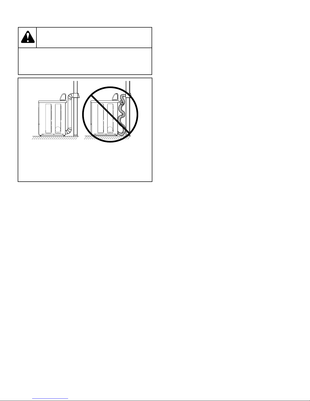
To reduce the risk of fire, DO NOT use plastic or thin
foil ducting to exhaust the dryer.
W354
DRY1915N_SVG
21
1. Correct
2. Incorrect
Figure 4
• DO NOT use plastic, thin foil or type B ducting. Rigid metal
duct is recommended.
• Locate dryer so exhaust duct is as short as possible.
• Be certain old exhaust ducts are cleaned before installing your
new dryer.
• Use 4 inch [102 mm] diameter rigid or flexible metal duct.
• The male end of each section of duct must point away from
the dryer.
• Use as few elbows as possible.
• Use of duct tape or pop-rivets on all seams and joints is rec-
ommended, if allowed by local codes. DO NOT use sheet
metal screws or fasteners on exhaust pipe joints which extend
into the duct and catch lint.
• For proper operation, it is important that the dryer has an am-
ple amount of outside make-up air. The free area of any open-
ing for the introduction of outdoor air must be at least 25 in.2
[163 cm2].
• When exhausting the dryer to the outdoors, the dryer can be
installed with "0" inch clearance at sides and rear. Clearance
of the duct from combustible construction must be a mini-
mum of 2 inches [5.08 cm] .
• Ductwork that runs through unheated areas must be insulated
to help reduce condensation and lint build-up on pipe walls.
• In mobile home installations, dryer exhaust duct must be se-
cured to mobile home structure.
• Dryer exhaust duct MUST NOT terminate under mobile
home.
• Exhaust duct must not be connected to any other duct, vent, or
chimney.
• Never install flexible duct in concealed spaces, such as a wall
or ceiling.
• Dryer exhausts 220 cfm (measured at back of dryer).
• Energy efficient buildings with low air infiltration rates
should be equipped with an air exchanger that can accommo-
date on demand make-up air needs in the laundry room. These
devices can be obtained through your building contractor or
building material suppliers.
• Static pressure in exhaust duct should not be greater than 0.6
inches water column [1.5 cm water column] measured with
manometer placed on exhaust duct two feet [610 mm] from
dryer (check with dryer running and no load).
• Exhausting dryer in hard-to-reach locations can be done by
installing 521P3 Flexible Metal Vent Kit (available as option-
al equipment at extra cost).
• Failure to exhaust dryer properly will void warranty.
NOTE: Venting materials are not supplied with the dry-
er (obtain locally).
Exhaust Direction
The dryer can be exhausted to the outdoors through the back, left,
right or bottom of the dryer. EXCEPTION: Gas dryers cannot be
vented out the left side because of the burner housing.
Dryer is shipped from factory ready for rear exhaust.
Exhausting the dryer through sides or bottom can be accomplish-
ed by installing a Directional Exhaust Kit, 528P3, available as
optional equipment at extra cost.
IMPORTANT: DO NOT block the airflow at the bottom
of the dryer’s front panel with laundry, rugs, etc. Block-
age will decrease airflow through the dryer, thus reduc-
ing the efficiency of the dryer.
Exhaust System
For best drying results, recommended maximum length of ex-
haust system is shown in Table 2 .
To prevent backdraft when dryer is not in operation, outer end of
exhaust pipe must have a weather hood with hinged dampers (ob-
tain locally).
NOTE: Weather hood should be installed at least 12 in-
ches [305 mm] above the ground. Larger clearances
may be necessary for installations where heavy snow-
fall can occur.
Installation
10 © Copyright, Alliance Laundry Systems LLC - DO NOT COPY or TRANSMIT Part No. 510963R7
Indice
Altri manuali ALLIANCE Asciugatrice

ALLIANCE
ALLIANCE BD3NGBGS303EW01 Manuale utente

ALLIANCE
ALLIANCE FDE3TRGS301NW10 Manuale utente

ALLIANCE
ALLIANCE 030 Series Manuale utente

ALLIANCE
ALLIANCE CA050L Manuale del proprietario

ALLIANCE
ALLIANCE 120 Series Manuale di istruzioni

ALLIANCE
ALLIANCE KEM377-1709 Manuale utente

ALLIANCE
ALLIANCE 513218R2 speed queen Manuale utente

ALLIANCE
ALLIANCE Speed Queen DR7003WG Manuale utente

ALLIANCE
ALLIANCE CA050L Manuale del proprietario

ALLIANCE
ALLIANCE BA120E Manuale utente


