Allied 95 Manuale del prodotto

OPERATOR AND PARTS MANUAL
022012 P4166
Loader
Models 95 & 195


3
Table of Contents - 95 & 195 Loader
Table of Contents
Introduction .................................................................................................................................4
• Terminology .....................................................................................................................4
• Hydraulic (Hose Kit).........................................................................................................5
Specifications...............................................................................................................................6
• 95 Loader ..........................................................................................................................6
• 195 Loader ........................................................................................................................8
Safety..........................................................................................................................................10
• Safety ..............................................................................................................................10
• General Safety................................................................................................................ 11
• Installation...................................................................................................................... 11
• Safety Decals..................................................................................................................12
• Important Precautions ...................................................................................................13
Operation ...................................................................................................................................14
• Operation........................................................................................................................14
• Operating Suggestions for Loading .............................................................................15
• Operating Suggestions for Backfilling .........................................................................16
• Attaching the Loader toYourTractor.............................................................................17
• Removing the Loader fromYourTractor.......................................................................19
General Instructions ..................................................................................................................21
Troubleshooting.........................................................................................................................22
Maintenance ..............................................................................................................................24
Lubrication .................................................................................................................................24
Bolt Torque .................................................................................................................................25
• Checking BoltTorque .....................................................................................................25
Parts............................................................................................................................................26
• Sub Frame Assembly and Parts List.............................................................................26
• Main Frame Assembly and Parts List ...........................................................................28
• Hydraulic Plumbing Assembly and Parts List..............................................................30
Assembly....................................................................................................................................32
• Hydraulic Cylinder Assembly........................................................................................32
Pre-delivery Check List..............................................................................................................33
Warranty.....................................................................................................................................34
Manufacturer’s statement: for technical reasons Buhler Industries Inc. reserves the right to modify
machinery design and specifications provided herein without any preliminary notice.
Information provided herein is of descriptive nature. Performance quality may depend on soil fertility,
applied agricultural techniques, weather conditions and other factors.
4
Introduction - 95 & 195 Loader
Introduction
Allied by Farm King front-end loaders are backed by years of extensive research. Factory testing
simulates specific operations to evaluate durability; days of continuous cycling in raising, twisting
and dropping loads using a programmed hydraulic power unit represents years of extreme use.
With one of the largest mounting kit application lists in the industry, there is an Allied front-end
loader available for nearly every tractor, large or small, new or old. Custom colors are available to
match all tractor brands which adds resale value and visual appeal.
Keep this manual handy for frequent reference. All new operators or owners must review the
manual before using the equipment and at least annually thereafter. Contact your Allied by Farm
King Dealer if you need assistance, information, or additional copies of the manual. Visit our
website at www.buhlerindustries.com for a complete list of dealers in your area.
The directions left, right, front and rear, as mentioned throughout this manual, are as seen facing
in the direction of travel of the implement.
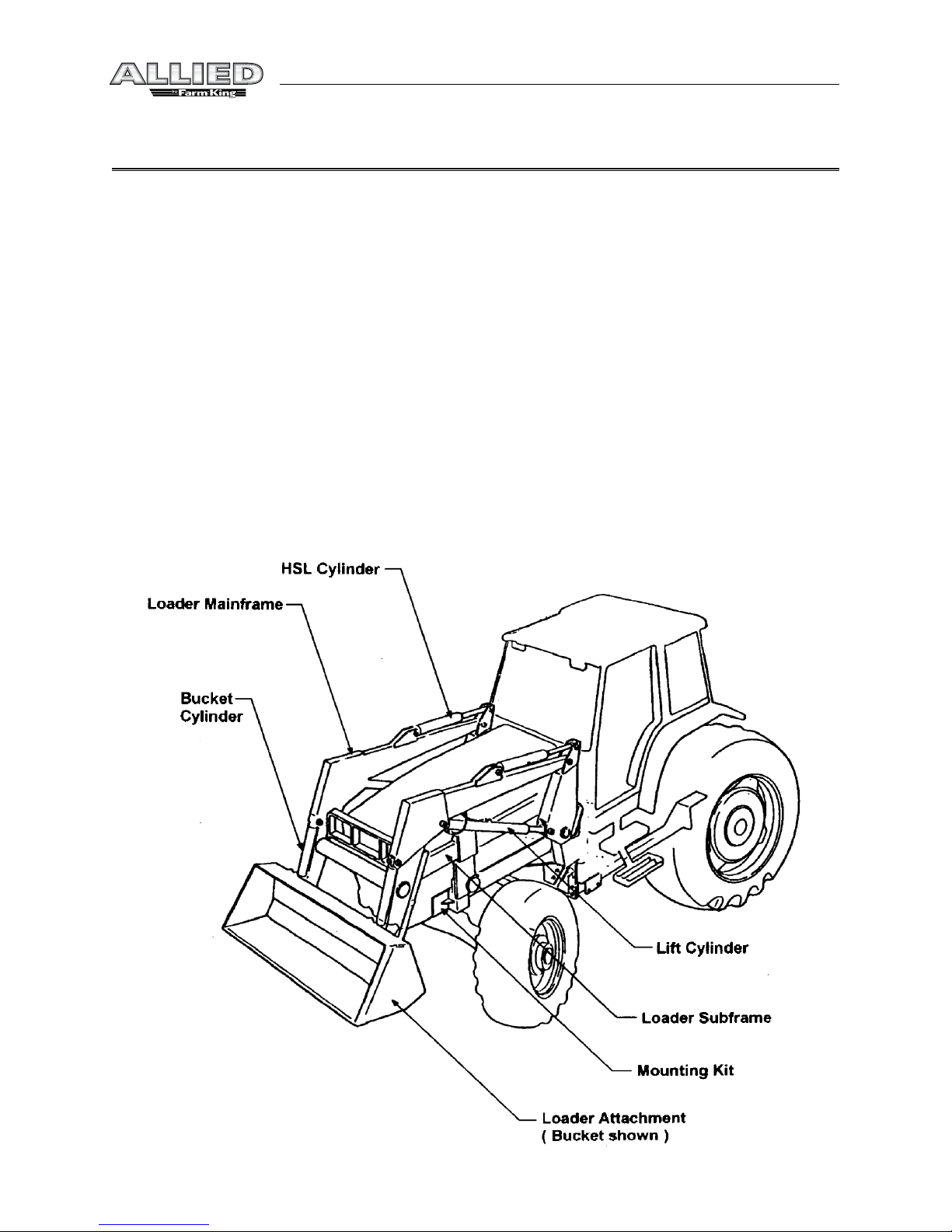
Terminology
Basic terminology used throughout this manual has been identified below. For part numbers and
further details refer to the Parts section.

5
Safety - 95 & 195 Loader
Hydraulic (Hose Kit)
Hose Kit “A”
Loader powered by the tractor remotes.
Consists of four hoses leading from loader
tubing to tractor remote couplers
Hose Kit “B”
Loader operated by an external OC or CC valve
that is powered from the tractor remotes.
Hose Kit “C”
Loader operated by an external valve that is
plumbed into the tractor hydraulic system.
Consists of 4 hoses leading from loader tubing
to external mounted valve plus the necessary
fittings, hoses and adapter blocks (if necessary)
to tap into tractor hydraulic system. Use valve
type shown with hose kit “C”

6
Specifications - 95 & 195 Loader
Specifications
95 Loader

7
Specifications - 95 & 195 Loader
Model number: 95
Mounting height: 23" (nominal)
Typical range: 20" - 26"
Description Bucket Lift
Bore 1.50" 1.50"
Rod 1.00" 1.00"
Stroke 13.25" 14.50"
Length 34.75" 37.00"
Length 21.50" 22.50
A - Maximum lift height to pivot point (full height): 78"
B - Clearance with bucket dumped: 61"
C - Reach at maximum height: 18"
D - Maximum dump angle: 45°
F - Bucket rollback angle: 14°
G - Digging depth: 3.9"
H - Overall height in carry position: 48" (12')
R - Rollback angle at full height: 96°
Estimated breakout force: 850 lbs
Estimated lift capacity: 525 lbs
Notes:
1 - Estimated values assume 1800 psi lift cylinder pressure
2 - Breakout force estimated as per ASAE S301.3 - 5.1.6 (net payloud applied at 31.5" forward of
bucket pivot)
3 - Lift capacity estimated a per ASAE S301.3 - 5.1.1 (net payload applied at bucket pivot point pin)
4 - Main pivot pins: 1.00" dia.
5 - All other pins 0.75" dia

8
Specifications - 95 & 195 Loader
195 Loader

9
Specifications - 95 & 195 Loader
Model number: 195
Mounting height: 26" (nominal)
Typical range: 23" - 29"
Description Bucket Lift
Bore 2.00" 2.00"
Rod 1.25" 1.25"
Stroke 13.38" 15.00"
Extended Length 37.00" 40.00"
Retracted Length 23.63" 25.00"
A - Maximum lift height to pivot point (full height): 90"
B - Clearance with bucket dumped: 74"
C - Reach at maximum height: 15"
D - Maximum dump angle: 40°
F - Bucket rollback angle: 19°
G - Digging depth: 3.3"
H - Overall height in carry position: 51" (12')
R - Rollback angle at full height: 104°
Estimated breakout force: 1600 lbs
Estimated lift capacity: 1150 lbs
Notes:
1 - Estimated values assume 2000 psi lift cylinder pressure
2 - Breakout force estimated as per ASAE S301.3 - 5.1.6 (net payload applied at 31.5" forward of
bucket pivot)
3 - Lift capacity estimated as per ASAE S301.3 - 5.1.1 (net payload applied at bucket pivot point pin)
4 - Main pivot pins: 1.00" dia.
5 - All other pins 0.75" dia

10
Safety - 95 & 195 Loader
Safety
Safety Instructions
Remember,YOU are the key to safety. Good safety practices not only protect you, but also the
people around you. Make these practices a working part of your safety program. Be certain that
everyone operating this equipment is familiar with the recommended operating and maintenance
procedures and follows all the safety precautions. Most accidents can be prevented. Do not risk
injury or death by ignoring good safety practices.
The alert symbol is used throughout this manual. It indicates attention is required and identifies
hazards. Follow the recommended precautions.
The safety alert symbol means…
ATTENTION! BECOME ALERT!YOUR SAFETY IS INVOLVED!
CAUTION
The caution symbol indicates a potentially hazardous situation
that, if not avoided, may result in minor or moderate injury. It
may also be used to alert against unsafe practices.
WARNING
The Warning Symbol indicates a potentially hazardous situation
that, if not avoided, could result in death or serious injury, and
includes hazards that are exposed when guards are removed. It
may also be used to alert against unsafe practices.
DANGER
The Danger Symbol indicates an imminently hazardous situation
that, if not avoided will result in death or serious injury. This
signal word is to be limited to the most extreme situations,
typically for machine components that, for functional purposes,
cannot be guarded.
Questo manuale è adatto per i seguenti modelli
1
Indice
Altri manuali Allied Caricatore compatto


