INSTALLATION GUIDE
AB* SERIES INSTALLATION GUIDE Page 3
THERMOSTAT
Select a thermostat that is commonly referred to as a
single stage cooling with electric sub base. This stat
will energize the fan on a demand for heat or cool.
Install the thermostat on an inside wall away from
drafts, lights or other heat sources in a location that
has good air circulation from the other rooms being
controlled by the thermostat. The thermostat should
be mounted 4’ to 5’ above the oor.
SEQUENCE OF OPERATION
Cooling (cooling only or heat pump with reversing
valve energized in heat mode): When the thermostat
calls for cooling, the blower relay is energized. The
N.O. contacts will close after a time delay then the
indoor blower will operate. The circuit between R and
Y is completed which causes the contactor on the
outdoor equipment to close, and start the compressor
and the outdoor fan motor.
Cooling (heat pump with reversing valve energized
in cooling mode): When the thermostat calls for
cooling, the circuit between R and G and R and O is
complete. Circuit R and O energizes the reversing
valve to the cooling position. Circuit R and G energizes
the blower relay. The N.O. contacts will close after a
time delay then the indoor blower will operate. The
circuit between R and Y is complete. Which causes
the contactor on the outdoor equipment to close, and
start the compressor and the outdoor fan motor.
Heating (electric heat only): When the thermostat
calls for heat, the circuit between R and W is completed.
The heat sequencer is energized. A time delay will
occur, which allows the heating element(s) and the
indoor blower motor to come on.
Heating (heat pump reversing valve energized
in the heat mode): When the thermostat calls for
heat, the circuits between R and B, R and Y and R
and G are completed. Circuit R and B energize the
reversing valve switching it to the heat position. Circuit
R and Y energized the outdoor unit contactor starting
the compressor and outdoor fan. Circuit R and G
energizes the blower relay stating the blower motor.
If the indoor room temperature should continue to fall,
circuit R and W2 is by the second-stage heat bulb
on the thermostat. Circuit R-W2 energizes the heat
sequencer. The completed circuit will energize the
supplemental electric heat.
Blower Time Delay: This unit is equipped with timed
on and a timed off relay. This relay delays the start
and delays the stopping of the indoor fan motor to
maximize the efciency of the unit.
Defrost: When the unit starts the defrost cycle
supplemental heat can be provided by connecting B
on the blower coil to the defrost relay on the outdoor
heat pump. This will complete the circuit between R
and B (in the blower coil) through a set of contacts in
the defrost relay in the outdoor unit. This circuit when
it is connected, will help prevent cold air from being
discharged from the indoor unit during the defrost.
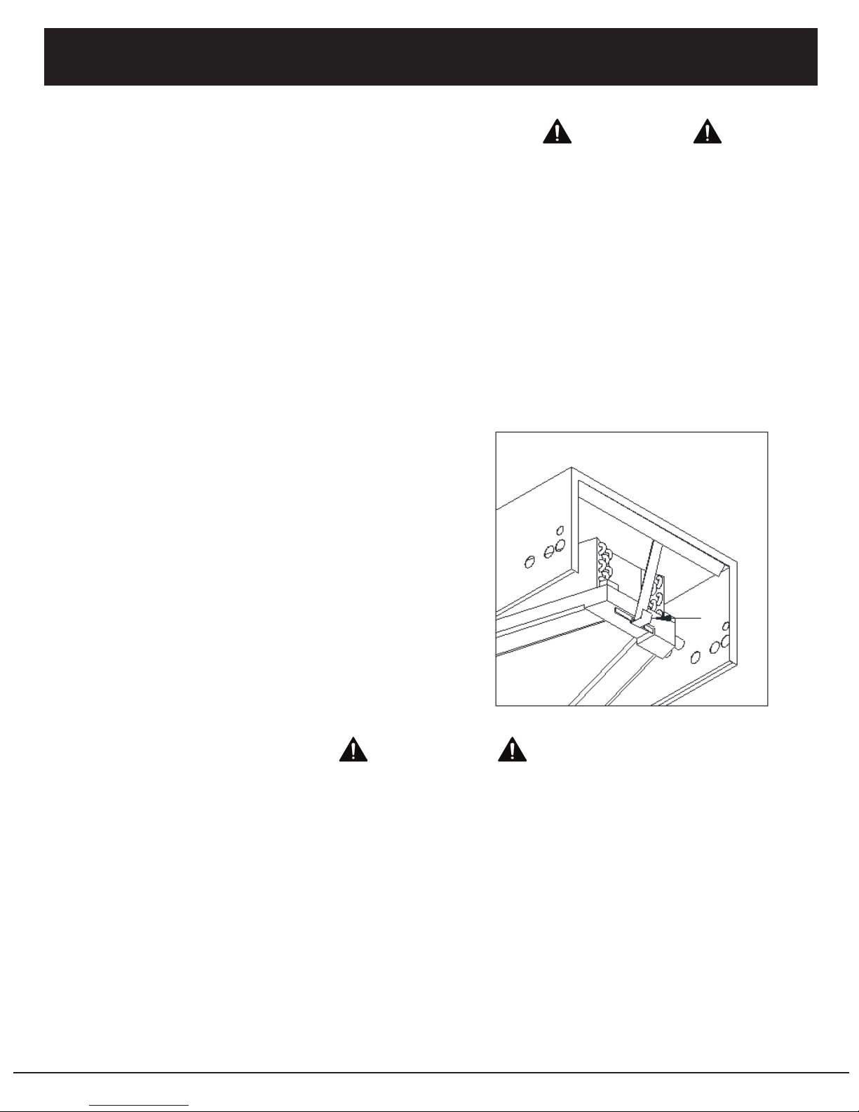
BLOWER
Units through three tons are supplied with a multi-
speed motor (high, medium, and low) with a direct
drive blower wheel which can obtain various air ows.
One and one and a half ton units are factory wired on
low speed, two ton units are factory wired on medium
speed, and two and half ton units are factory wired and
shipped with the blower connected for high speed. If
a lower blower speed is required, disconnect all power
to the unit, remove the factory wired indoor fan motor
lead from the fan relay and place an insulated cap
on the removed motor lead. Remove the insulated
cap from the desired indoor fan motor lead, place a
spade connector on the lead and connect it to the fan
relay where the original lead was connected. The
black motor lead is high speed, the red motor lead
is low speed, and the blue motor lead (if available) is
medium speed. Be sure to check the air ow and the
temperature drop across the evaporator coil to ensure
that you have sufcient air ow. For ECM option refer
to ECM wiring diagram for speed tap placement.
(ECM speed taps are 24v to energize) See page 8.
START UP
Once all connections are complete the unit should be
started up , and a check out of the completed system
should be performed. Before performing any system
test, make sure that all grilles, registers, and dampers
are open and set to the correct position. Also make
certain that the air lter is installed in the return air prior
to running the air handler.
A performance test should be conducted in the
accordance with the outdoor equipment manufacturer’s
instructions. Airow tests should be conducted in the
heating and cooling modes to ensure satisfactory
operation.