ALTAI B5 Manuale utente

Altai Technologies Ltd. All rights reserved
ALTAI B5
WIRELESS PTP/PTMP BRIDGE
QUICK SETUP GUIDE
Version 1.0
Date: October, 2013
Altai Technologies Ltd. All rights reserved
B5 Quick Installation Guide
TPS13-010_rev1.0
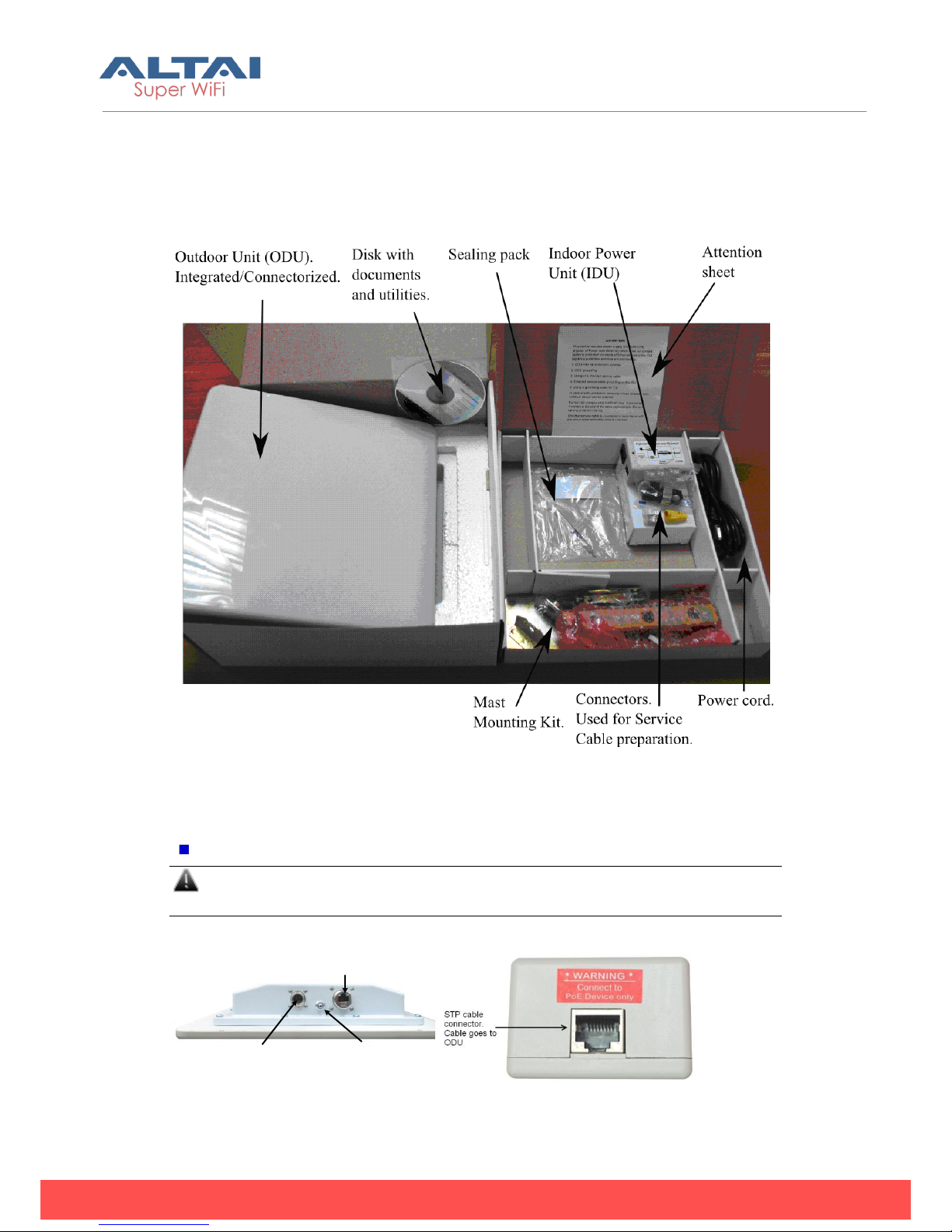
1. Unpack
After receiving the equipment please locate the following items in your box as shown
on the picture below:
2. Switch on
Connect ODU and IDU with STP/FTP cable.
The total cable length between LAN (behind IDU) and ODU should not be
longer than 100 meters.
ODU:
IDU:
Console port Grounding clamp/damping
system window
DO NOT BLOCK!
ALWAYS LOOKS DOWN!
Service cable
RJ-45 connector
Figure 2. Ind
oor Unit
Figure 1. Outdoor Unit
Figure 2. Iutdoor Unit
Altai Technologies Ltd. All rights reserved
B5 Quick Installation Guide
TPS13-010_rev1.0
When ODU module has one or several N-type
connectors for external antenna.
If other IDUs used, please study
their installation instructions in
Technical User Manual.
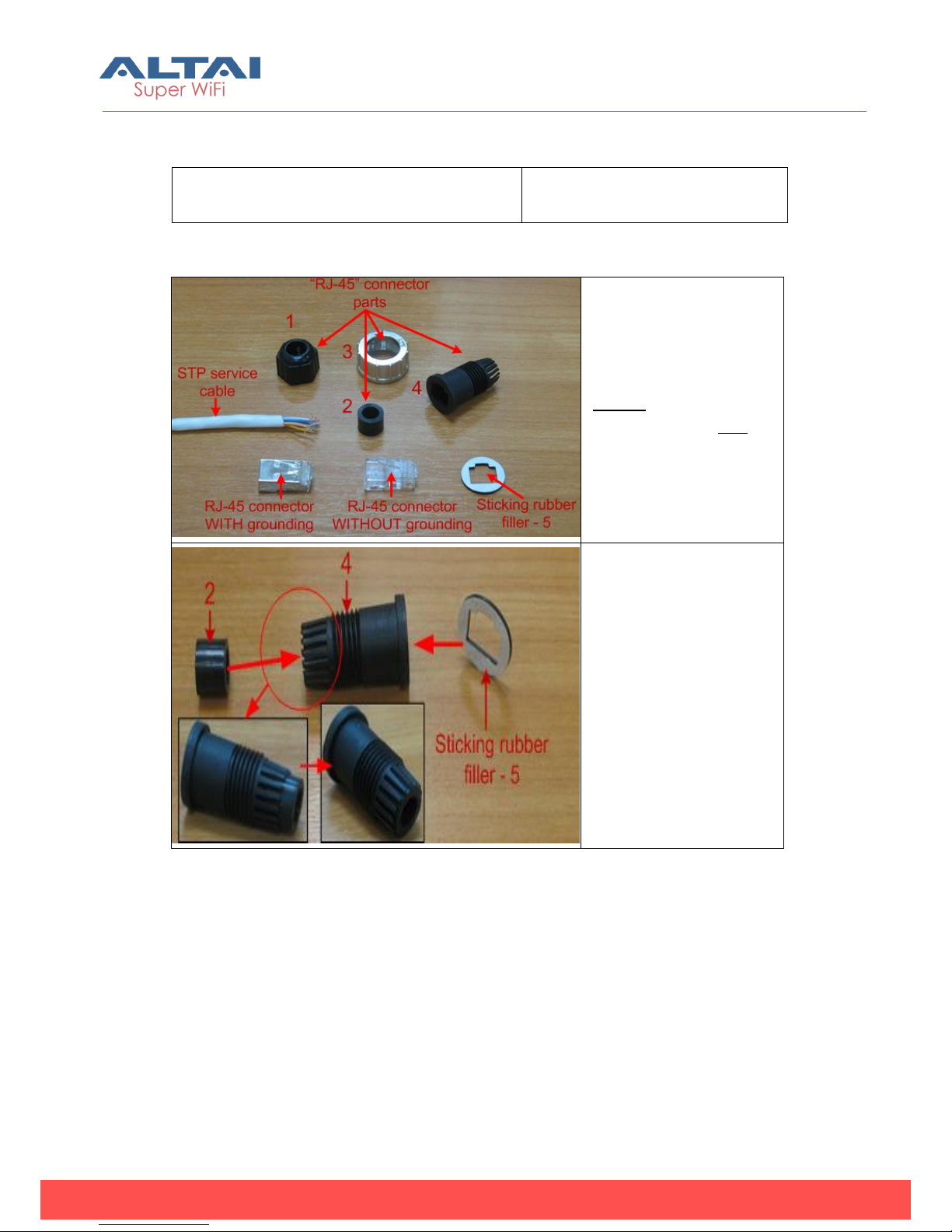
Cable preparation:
Step 1.
Peel STP service cable
and prepare “RJ-45”
connector parts.
Use RJ-45 connector
without grounding here
(RJ-45 connector with
grounding should be
used for connecting
service cable to IDU).
Step 2.
Stick rubber filler –5 on
the Part 4, previously
having removed
protective white layer
from rubber filler -5.
Insert Part 2 inside part 4
up to the stop. Part 2
must be entirely within
Part 4.
Altai Technologies Ltd. All rights reserved
B5 Quick Installation Guide
TPS13-010_rev1.0
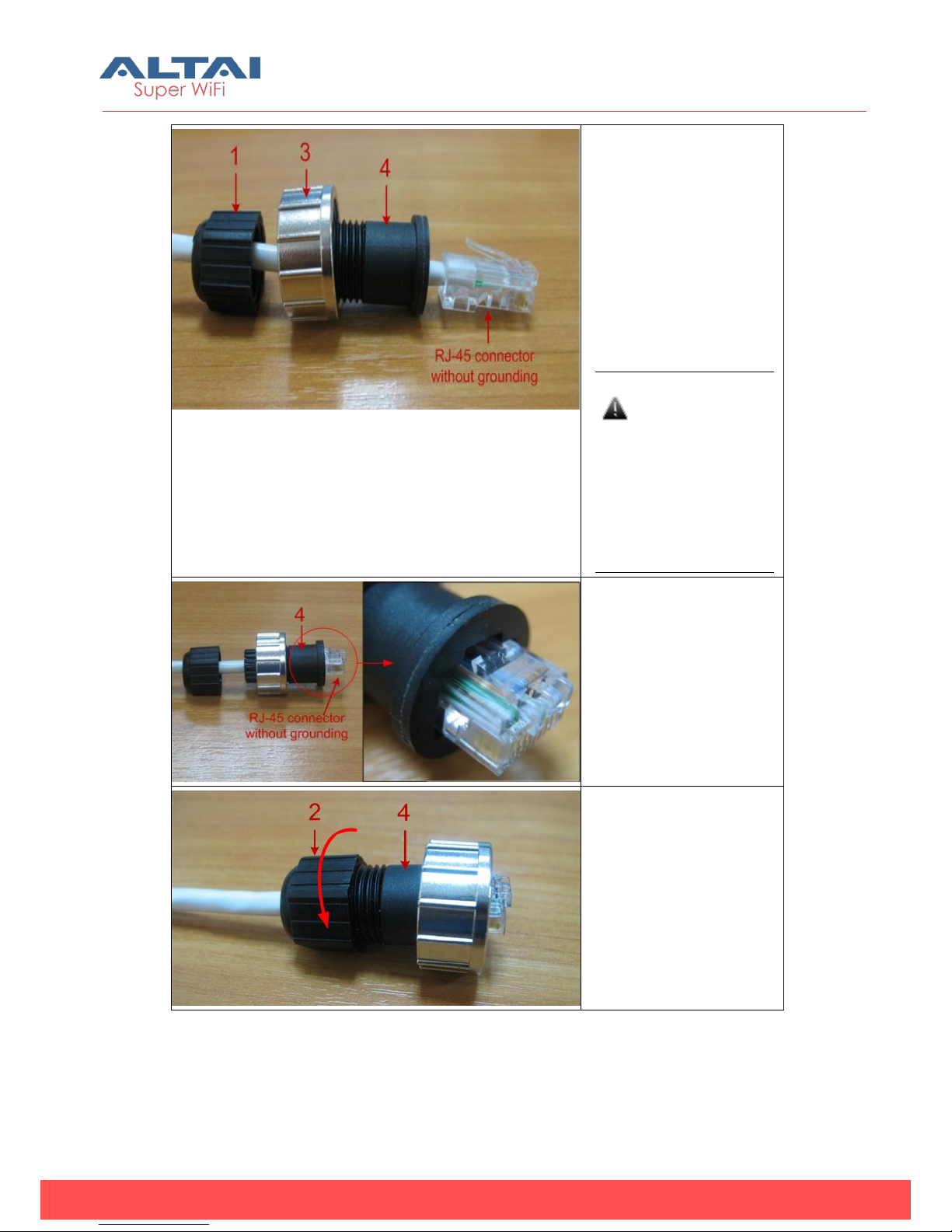
Step 3.
Put connector parts on
the STP service cable as
shown.
Attach RJ-45 connector
without grounding to the
STP service cable
according to the “RJ-45”
soldering scheme
(below in this section)
and crimp the
connector using a crimp
tool.
Please tightly
crimp the RJ-45
connector. Not
crimped or badly
crimped
connector
damages the unit
when assembled
into it which is not
considered as a
warranty case.
Step 4.
Put Part 4 on the
attached in the previous
step RJ-45 connector.
Step 5.
Screw Part 2 on Part 4.
This fixes the “RJ-45”
connector on the cable.
Check that the
connector is properly
fixed on the cable.
Altai Technologies Ltd. All rights reserved
B5 Quick Installation Guide
TPS13-010_rev1.0
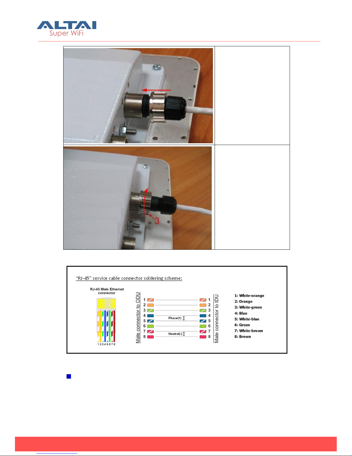
Step 6.
Assemble the connector
to the unit.
Step 7.
Fix the connector by
screwing Part 3.
Now the connector is
hermetically attached
to the unit. No
additional sealing
needed.
Figure 3. RJ-45 cable connector soldering scheme
Power on
Plug the power cord into the IDU Power supply connector and to the Power supply
socket (220V 50 Hz or 110V 60 Hz depending on the country of residence).

Altai Technologies Ltd. All rights reserved
B5 Quick Installation Guide
TPS13-010_rev1.0
Accessing the Unit:
To access the unit via console:
1. Using Altai Console Cable please connect the unit’s console port (see Fig. 1) to
the
COM-port of your PC/Laptop.
In order to accomplish the steps described in this
section your PC/Laptop must be equipped with a
COM-port
2. Locate the power cord in the package
3. Plug the power cord into the IDU power supply connector and to the power
supply socket
(220V 50 Hz or 110V 60 Hz depending on the country of residence)
4. Green power indicator on the IDU must light up
5. Power your PC/Laptop on
Following step’s screenshots are taken from Microsoft
Windows XP. You can also perform this procedure in
Microsoft Windows 98/NT/2003
6. Run HyperTerminal. See Figure 4
Figure 4. Locate HyperTerminal
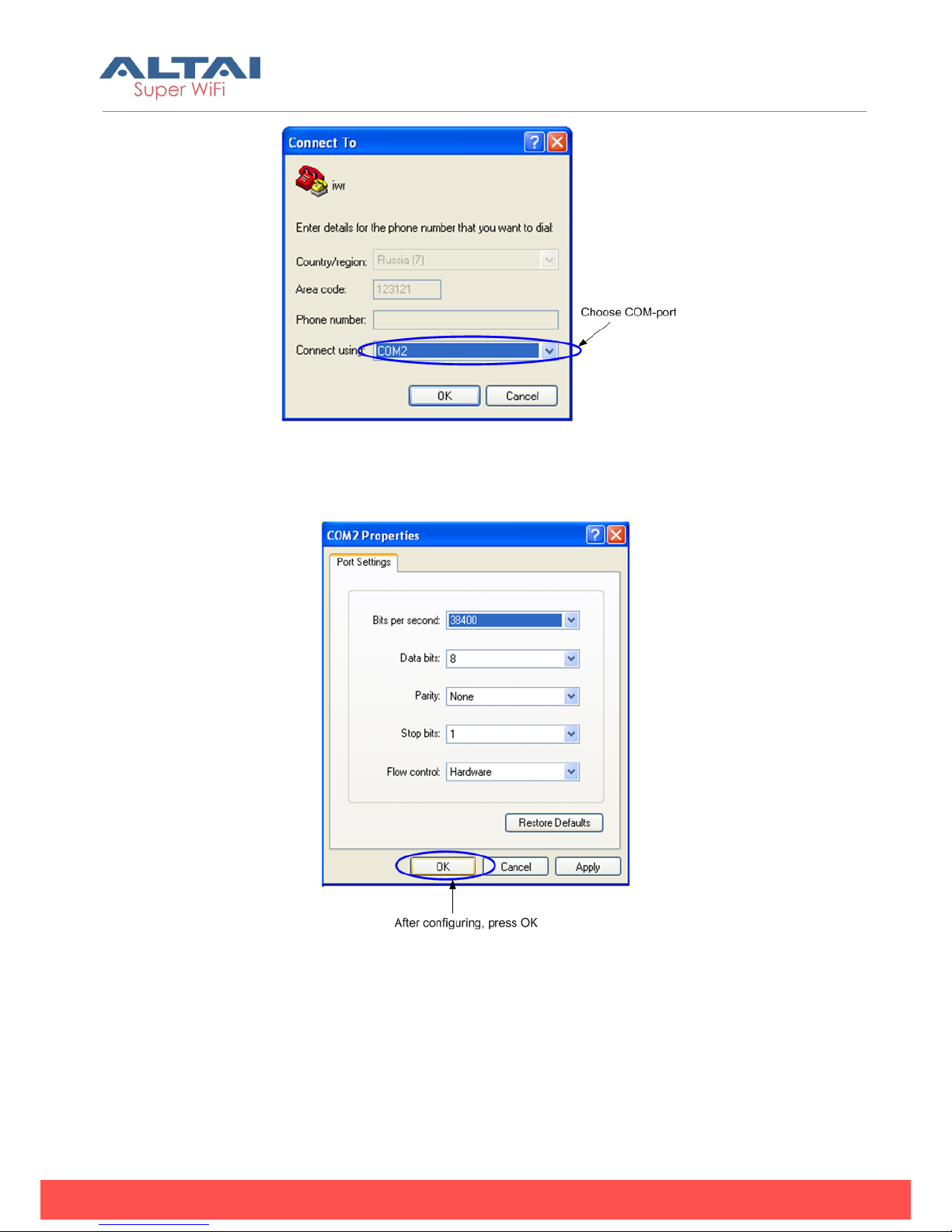
7. Indicate connection name (e.g. “IWR Lab Test”) and specify the COM-port name
to which the unit is connected. See Figure 5
Altai Technologies Ltd. All rights reserved
B5 Quick Installation Guide
TPS13-010_rev1.0
Figure 5. Select the port
8. Specify port parameters exactly as shown on Figure 6
Figure 6. Port parameters
9. If you connected everything properly, selected the right port and made its
configuration right,
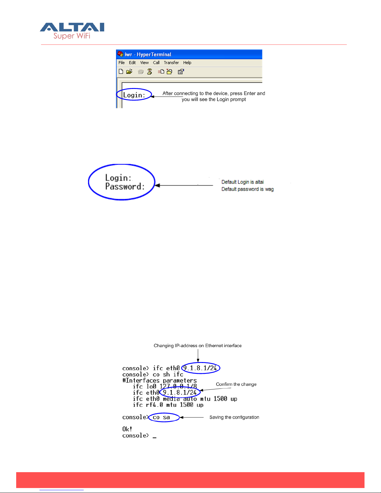
After pressing enter on the white blank screen (after step 8) you should see
WANFleX OS prompt as shown on Figure 7
Altai Technologies Ltd. All rights reserved
B5 Quick Installation Guide
TPS13-010_rev1.0
Figure 7. WANFleX OS prompt
10. Your device has a factory configuration. Default login is altai, default password is
wag. Once this is done, you will see CLI (Command Line Interface). See Figure 8
Figure 8. “Login” screen
11. In order for your unit to be accessible from your LAN/PC/Laptop via Ethernet, you
should configure eth0 interface IP-address so the unit would allocate in the
desired LAN (or accessible from your PC/Laptop Ethernet adapter). You can
change this IP-address via “ifc eth0” command as shown on figure 9. After
changing the IP-address, save the configuration using “co sa” command. In the
example given the IP-address being assigned to eth0 interface is 9.1.8.1 with
mask length 24 (255.255.255.0). In order to check whether your changes were
correct, use “co sh ifc” command which shows configuration for all interfaces of
the unit. Do not forget to save your configuration using “co sa” (config save)
command.
Figure 9. Changing IP-address on eth0 interface
Altai Technologies Ltd. All rights reserved
B5 Quick Installation Guide
TPS13-010_rev1.0
12. If all your settings are correct you can connect the unit to your LAN using UTP
cable with RJ-45 connectors (Ethernet port of the unit is located on IDU).
To access the unit via Ethernet:
If your PC/Laptop does not have a COM-port or you want to plug the unit to the LAN
switch you can configure it using Telnet protocol.
The default IP-address assigned to the eth0 interface of the unit is 192.168.1.20 with
255.255.255.0 mask.
If you connect the unit directly to the LAN/PC/Laptop you should either change the
IP-address on the Ethernet adaptor or create an alias IP-address which would be
located in 192.168.1.0/24 network.
Connect the unit to LAN/PC/Laptop using UTP cable with RJ-45 connectors.
The procedure is the following:
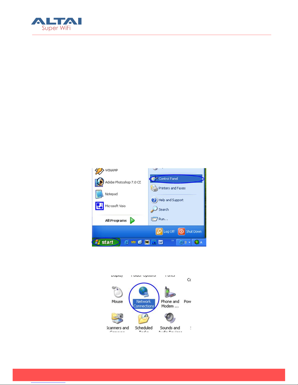
1. Open the Control Panel in Windows. See Figure 10
Figure 10. Open Control Panel
2. Open “Network connections” icon. See Figure 11
Figure 11. “Network connections”
Altai Technologies Ltd. All rights reserved
B5 Quick Installation Guide
TPS13-010_rev1.0
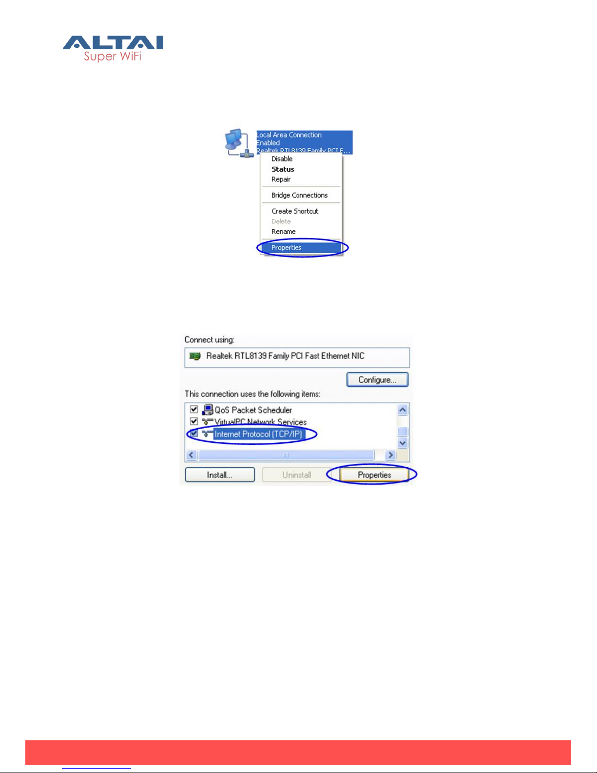
3. In “Network connections” folder right mouse button click on the LAN connection
and click “Properties”. See Figure 12
Figure 12. LAN Connection properties
4. Choose “Internet protocol (TCP/IP)” and click “Properties”. See Figure 13.
5.
Figure 13. Internet Protocol Properties
5. If you want to connect to the unit using PC/Laptop you can just change an IP-
address on the Ethernet adaptor to some address from 192.168.1.0/24 network
(e.g. change “IP-address” field to “192.168.1.23” and “Subnet mask” to
“255.255.255.0”). After that click OK and move to step 7. See Figure 14
Indice
Altri manuali ALTAI Hardware di rete

Manuali Hardware di rete popolari di altre marche

Matrix Switch Corporation
Matrix Switch Corporation MSC-HD161DEL Manuale utente

B&B Electronics
B&B Electronics ZXT9-IO-222R2 Manuale utente

Yudor
Yudor YDS-16 Manuale utente

D-Link
D-Link ShareCenter DNS-320L Manuale utente

Samsung
Samsung ES1642dc Istruzioni per l’uso

Honeywell Home
Honeywell Home LTEM-PV Istruzioni per il montaggio


