PRODUCT DESIGN
4Rev.1
General Operation
This GUID furnace is equipped with an electronic ignition
device to light the burners and an induced draft blower to
exhaustcombustionproducts.
Aninterlock switch prevents furnaceoperation ifthe blower
door is not in place. Keep the blower access doors in place
except for inspection and maintenance.
This furnace is also equipped with a self-diagnosing elec-
tronic control module. In the event a furnace component is
notoperating properly, the controlmodule LEDwill flashon
and off in a factory-programmed sequence, depending on
the problem encountered. This light can be viewed through
theobservation window in theblower access door. Referto
the
Troubleshooting Chart
for further explanation of the
LED codes and
Abnormal Operation - Integrated Ignition
Control
section in the Service Instructions for an explana-
tion of the possible problem.
Theratedheatingcapacityofthefurnaceshouldbe greater
than or equal to the total heat loss of the area to be heated.
The total heat loss should be calculated by an approved
method or in accordance with “ASHRAE Guide” or “Manual
J-LoadCalculations” published bytheAirConditioning Con-
tractors of America.
*Obtain from: American National Standards Institute 1430
Broadway New York, NY 10018
LocationConsiderations
• The furnace should be as centralized as is practical
with respect to the air distribution system.
• Do not install the furnace directly on carpeting, tile,
or combustible material other than wood flooring.
• When suspending the furnace from rafters or joists,
use 3/8" threaded rod and 2” x 2” x 3/8” angle as
shownin theInstallationand ServiceInstructions.The
length of the rod will depend on the application and
clearance necessary.
• When installed in a residential garage, the furnace
mustbe positioned sotheburnersand ignition source
are located not less than 18 inches (457 mm) above
the floor and protected from physical damage by ve-
hicles.
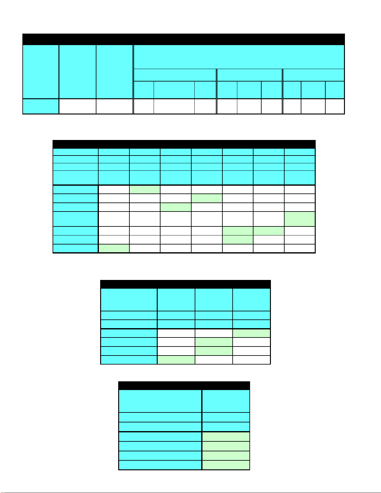
Accessibility Clearances (Minimum)
UPFLOW HORIZONTAL
LEFT HORIZONTAL
RIGHT
FRONT 61Alcove Alcove
RIGHT 0612
LEFT 0126
REAR 000
TOP 166
FLUE 626262
FLOOR CCC
MINIMUM CLEARANCES TO COMBUSTIBLE MATERIALS
(INCHES)
1= 3 inch when usin
Type B-1 vent is used.
2 = 1 inch when Type B-1 vent is used.
C = If placed on combustible floor, floor MUST be wood ONLY.
36" at front is required for servicing or cleaning.
Note: In all cases accessibility clearance shall take prece-
dence over clearances from the enclosure where accessi-
bility clearances are greater. All dimensions are given in
inches.
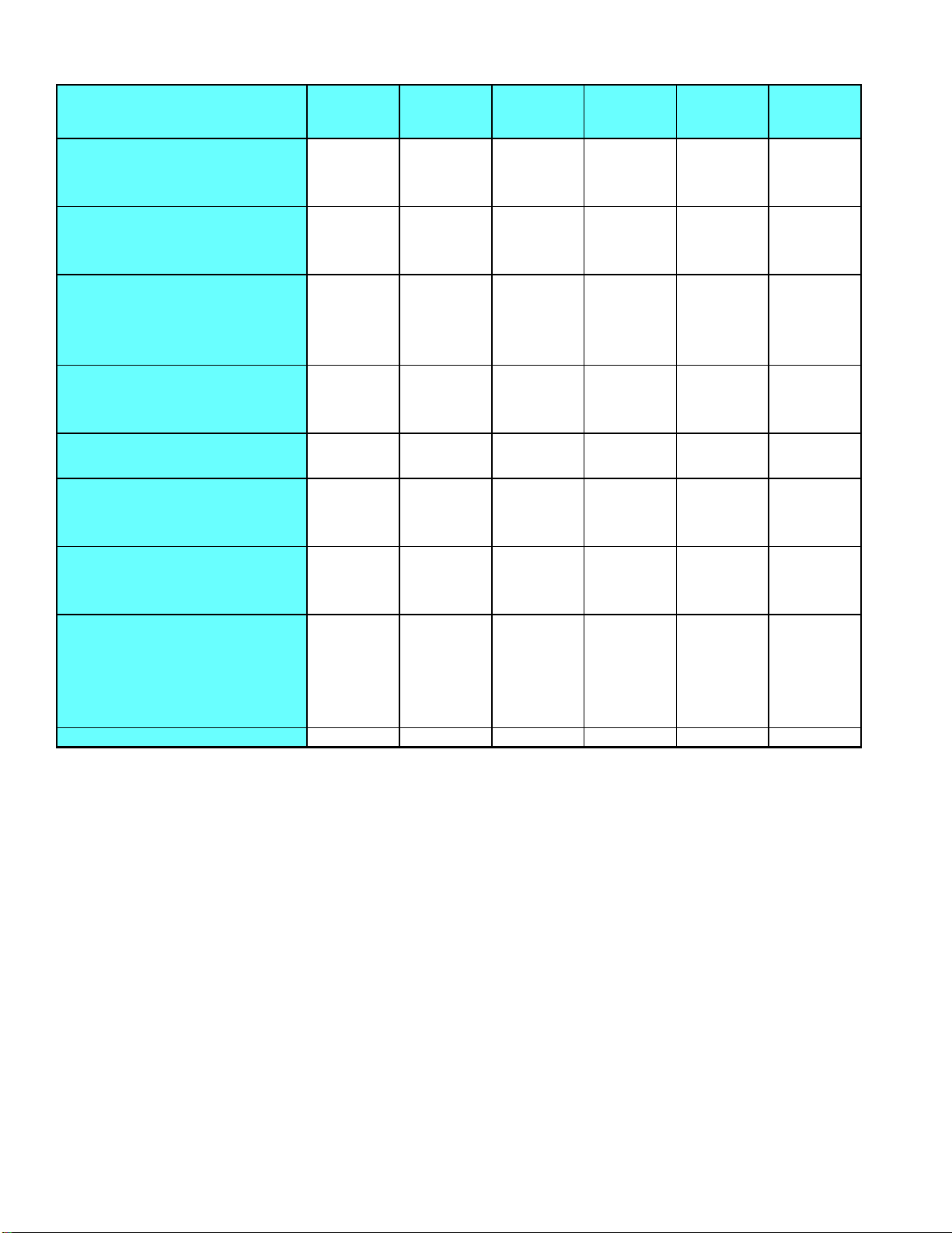
HighAltitudeDerate
When this furnace is installed at high altitude, the appropri-
ate High Altitude orifice kit must be installed. This is re-
quiredduetothenaturalreductioninthedensity of both the
gas fuel and combustion air as altitude increases. The kit
will provide the proper design certified input rate within the
specifiedaltituderange.
MODEL
NUMBER 0 to
6000 ft. 6001 to
11000 ft. 6001 to
11000 ft.
GUID
LPTK09
Propane
Conversion Kit
(#55 Orifice)
HANG07
High Altitude
Natural Gas Kit
(#45 Orifice)
HALP09
High Altitude
Propane Gas Kit
(#56 Orifices)
PROPANE AND HIGH ALTITUDE KITS
High altitude kits are purchased according to the installa-
tion altitude and usage of either natural or propane gas.
Refer to the chart above for a tabular listing of appropriate
altitude ranges and corresponding manufacturer’s high al-
titude Natural Gas and Propane Gas kits. For a tabular list-
ing of appropriate altitude ranges and corresponding
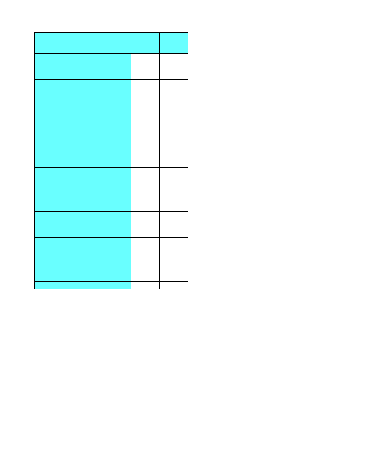
manufacturer's High Altitude Pressure Switch kits, refer to
either the
Pressure Switch Trip Points & Usage Chart
in
this manual or the
Accessory Charts
in Service Instruc-
tions.