American Dynamics ADQUAD27 Manuale del proprietario

English
Quad Processors
Installation and Operation
ADQUAD27, ADQUAD27-1, ADQUAD47,
ADQUAD47-1, ADQUAD77, ADQUAD77-1,
ADQUAD87 and ADQUAD87-1
Part Number 8000-2133-01 REV D

Installation and Operation
ii
Notice
The information in this manual was current when published. The manufacturer reserves the right to revise
and improve its products. All specifications are therefore subject to change without notice.
Copyright
Under copyright laws, the contents of this manual may not be copied, photocopied, reproduced, translated
or reduced to any electronic medium or machine-readable form, in whole or in part, without prior written
consent of Sensormatic Electronics. © Copyright 1997-2003, Sensormatic Electronics Corporation.
American Dynamics
6795 Flanders Drive
San Diego, CA 92121-2903 U.S.A.
Customer Service
Thank you for using American Dynamics products. We support our products through an extensive
worldwide network of dealers. The dealer through whom you originally purchased this product is your point
of contact if you need service or support. Our dealers are empowered to provide the very best in customer
service and support. Dealers should contact American Dynamics at (800) 507-6268 or (561) 912-6259 or on
the Web at www.americandynamics.net.
English

Quad Processors
iii
WARNINGS
WARNING: DO NOT REMOVE COVER! NO USER SERVICABLE PARTS INSIDE. REFER
SERVICING TO QUALIFIED SERVICE PERSONNEL.
DO NOT INSTALL THIS PRODUCT IN HAZARDOUS AREAS WHERE HIGHLY
COMBUSTIBLE OR EXPLOSIVE PRODUTS ARE STORED OR USED.
TO REDUCE RISK OF FIRE OR ELECTRIC SHOCK, DO NOT EXPOSE THIS
APPLIANCE TO RAIN OR MOISTURE.
THE LIGHTNING FLASH/ARROWHEAD SYMBOL, WITHIN AN EQUILATERAL
TRIANGLE, ALERTS THE USER TO THE PRESENCE OF A SHOCK HAZARD WITHIN
THE PRODUCT’S ENCLOSURE.
CAUTION: This equipment generates, uses, and can radiate radio frequency energy and, if not
installed and used in accordance with the instruction manual, may cause interference
to radio communications. It has been tested and found to comply with the limits for a
Class A computing device pursuant to subpart B of part 15 of FCC rules, which are
designed to provide reasonable protection against such interference when operated in
a commercial environment. Operation of this equipment in a residential area is likely to
cause interference in which case the user at his own expense will be required to take
whatever measures may be required to correct the interference.
Changes or modifications not expressly aproved by the party responsible for
compliance could void the user's authority to operate the equipment.
This Class A digital apparatus meets all requirements of the Canadian Interference
Causing Equipment Regulations.
Cet appareil numérique de la Classe A respecte toutes lex exigencies du Réglement sur
le materiél brouilleur du Canada.

Installation and Operation
iv
Suggested Installation of Standard Quad Processor
Suggested Installation of Premium Quad Processor

Quad Processors
1
ADQUAD27 /
ADQUAD27-1
ADQUAD77 /
ADQUAD77-1
ADQUAD47 /
ADQUAD47-1
ADQUAD87 /
ADQUAD87-1
Camera Type B&W Color B&W Color
Time/Date/Title Single (monitor out only) Dual (monitor and VCR)
Remote Control N/A RS-232
Zoom on Playback N/A Yes
Video Input Channels Four
Video Loop Through Yes
On-screen Setup Yes
Alarm Sensor Type Normally Open (NO)/Normally Closed (NC); (Selectable)
Alarm Inputs Four
Alarm Call Full Screen Yes
Individual Dwell Yes
Security Lockout Yes
Rack Mount Fits standard 19” rack; single and dual kits available (optional)
Video Output Monitor: 1 V p-p; VCR: 1 p-p; Loop: 1 V p-p
Time/Date/Title Built-in clock with backup power; 8 characters for each title
Alarm Output NO and NC contacts: 1 Amp @ 24 VDC maximum
Alarm Duration Adjustable; 1 second to nonstop
Camera Dwell Adjustable; 1 second to 99 seconds
Remote Control N/A 1 to 9 units addressable
Refresh Rate 30 (NTSC/EIA); 25 (PAL/CCIR)
Resolution 512x512 (full screen) 1024x512 (full screen)
Number of Colors 256 gray scale 16.7M colors 256 gray scale 16.7M colors
Power Consumption 7.5 to 8.5 watts at 10V to 14V DC
Dimensions 215Wx309Dx44H (mm); 8.5Wx12.2Dx1.75H (in)
Operating Temperature 0° to 45°C or 32° to 113° F

Installation and Operation
2
PREMIUM QUAD PROCESSOR FRONT PANEL CONTROLS
1power—Green LED indicates the unit is on.
2 vcr/PB+ — Places unit in playback mode. Selects DIRECT for VCR setup, or FRAME or
FIELD for playback. Changes display 5–8 buttons to zoom or freeze function.
3seq—Begins or ends sequential display of full screen images at programmed dwell rate.
4set—Pressing set and display 9 button simultaneously begins or ends menu setup.
Pressing display 7 simultaneously with set restores factory default settings. Pressing set
while in playback mode returns monitor output to a live display.
5 display 5 — Displays camera 1 full screen in live mode. In playback mode, zooms or
freezes image in first quadrant. Selects alphanumeric character in menu setup.
6 display 6 — Displays camera 2 full screen in live mode. In playback mode, zooms or
freezes image in second quadrant. Selects alphanumeric character in menu setup.
7 display 7 — Displays camera 3 full screen in live mode. In playback mode, zooms or
freezes image in third quadrant. Moves cursor forward in menu setup.
8 display 8 — Displays camera 4 full screen in live mode. In playback mode, zooms or
freezes image in fourth quadrant. Moves cursor backwards in menu setup.
9 display 9 — Displays all four images in live or playback mode.

Quad Processors
3
PREMIUM QUAD PROCESSOR REAR PANEL CONNECTORS
1power—Power input connector. Only use 12 VDC center-positive power supply.
2alarm—DB9-P connector. See Alarm Connector Pin Assignments for details.
3 remote — DB9-S connector. See Remote Connector Pin Assignments for details.
4 ground — Chassis ground point with Phillips screw connector.
5 monitor — BNC connector. Delivers display output to a monitor terminated in 75 ohms.
6 vcr in — BNC connector. Accepts video signal from an attached VCR for playback.
7 vcr out — BNC connector. Delivers video signal in quad format to an attached VCR.
8 camera termination — Set camera termination ON (75Ω) or OFF (HiZ)
9 cam 1-4 in — BNC connectors. Accept video input. Auto-terminated in 75 ohms
10 cam 1-4 out — BNC connectors. Deliver video output. Auto-terminated in 75 ohms.

Installation and Operation
4
STANDARD QUAD PROCESSOR FRONT PANEL CONTROLS
1power—Green LED indicates the unit is on.
2 vcr/PB+ — Places unit in playback mode.
3 seq — Begins or ends sequential display of full screen images at programmed dwell rate.
4 set — Pressing set and display 9 button simultaneously begins or ends menu setup.
Pressing display 7 simultaneously with set restores factory default settings.
5display5—Displays camera 1 full screen in live mode. Selects alphanumeric character in
menu setup.
6display6—Displays camera 2 full screen in live mode. Selects alphanumeric character in
menu setup.
7 display 7 — Displays camera 3 full screen in live mode. Moves cursor forward in menu
setup.
8 display 8 — Displays camera 4 full screen in live mode. Moves cursor backwards in
menu setup.
9 display 9 — Displays all four images in live mode.

Quad Processors
5
STANDARD QUAD PROCESSOR REAR PANEL CONNECTORS
1power—Power input connector. Only use 12 VDC center-positive power supply.
2 alarm — DB9-P connector. See Alarm Connector Pin Assignments for details.
3 ground — Chassis ground point with Phillips screw connector.
4 monitor — BNC connector. Delivers display output to a monitor terminated in 75 ohms.
5 vcr out — BNC connector. Delivers video signal in quad format to an attached VCR.
6 vcr in — BNC connector. Accepts video signal from an attached VCR for playback.
7 camera termination — Set camera termination ON (75Ω) or OFF (HiZ)
8 cam 1-4 in — BNC connectors. Accept video input. Auto-terminated in 75 ohms
9 cam 1-4 out — BNC connectors. Deliver video output. Auto-terminated in 75 ohms.
Installation and Operation
6
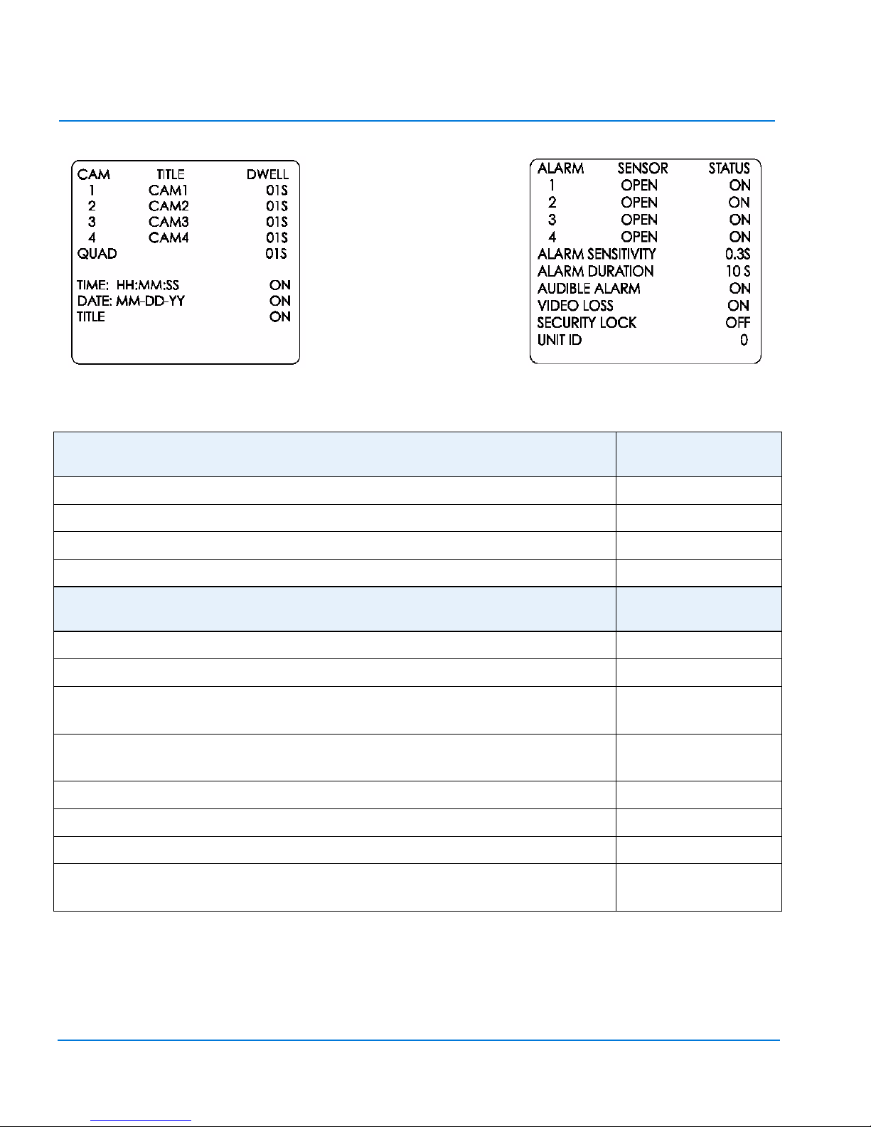
MENU ONE SETTINGS: RANGE DEFAULT
SETTING
TITLE: Eight characters; A–Z, 0–9, :, /, +,-, space CAM1 thru CAM4
DWELL: 0–99 seconds 01S (One second)
TIME: HH:MM:SS; DATE: MM-DD-YY or DD-MM-YY (PAL) ON
TILE: ON or OFF ON
MENU TWO SETTINGS: RANGE DEFAULT
SETTING
SENSOR: Attached device is OPEN (NO) or CLOSED (NC) OPEN
STATUS: Unit response to attached sensor is ON or OFF ON
ALARM SENSITIVITY: Shortest pulse that triggers alarm response; 0.1
seconds to 0.8 seconds
0.3S
ALARM DURATION: Response after end of input; 0seconds to
59 minutes
10S
AUDIBLE ALARM: Sound during alarm; ON or OFF ON
VIDEO LOSS: Video loss triggers alarm; ON or OFF ON
SECURITY LOCK: Disables front panel controls; ON or OFF OFF
UNIT ID (Premium units only): Unit number returned at TX pin of
remote connector; control up to nine units, 1–9 0 (no ID)
Altri manuali per ADQUAD27
1
Questo manuale è adatto per i seguenti modelli
7
Indice
Lingue:
Altri manuali American Dynamics Hardware per computer


Manuali Hardware per computer popolari di altre marche

EMC2
EMC2 VNX Series Manuale del proprietario

Panasonic
Panasonic DV0PM20105 Manuale utente

Mitsubishi Electric
Mitsubishi Electric Q81BD-J61BT11 Manuale utente

Gigabyte
Gigabyte B660M DS3H AX DDR4 Manuale utente

Raidon
Raidon iT2300 Manuale utente

National Instruments
National Instruments PXI-8186 Manuale utente


