Amplink PDM Manuale utente
Page 1 of 12
User Manual
The Amplink PDM is built upon the strong reputation of the original PDM60 with added and improved
features to make 12V power distribution even easier.
Table of Contents
Package Contents 2
Specifications 2
Device Overview 3
Installation Basics 4
Amplink PDM App 4
App Connection Instructions 5
App Connection Troubleshooting 8
App Overview 9
Wiring and App Setup Example 1 10
Wiring and App Setup Example 2 11
Page 2 of 12
Package Contents
· 1 - Amplink Power Distribution Module
· 1 - Ground bus kit with cover
· 6 - ¼” ring terminal – for use on accessory ground wires connected to the ground bus
· 1 - 6MM bolt & nut - used for connecting all accessory ground wires to the main ground bus
· 6 - Posi-Lock Connectors – for easy and secure connections of 14 or 16ga wires
· 3 - Posi-Tap Connector – for easy connection to any 18ga wire for triggering
Specifications
Operating Voltage: 6-20V for 12V systems
Total Current Capacity: 60 Amp maximum continuous
Outputs: 6 (20A Max) High side outputs
Inputs (Triggers): 3, voltage or ground configurable inputs
Operating Temperature: -40 to 185°F / -40 to 85°C
Connections: Sealed 18 inch hardwire leads
Water Protection: Fully encapsulated waterproof
Weight: 10 oz / 284 g
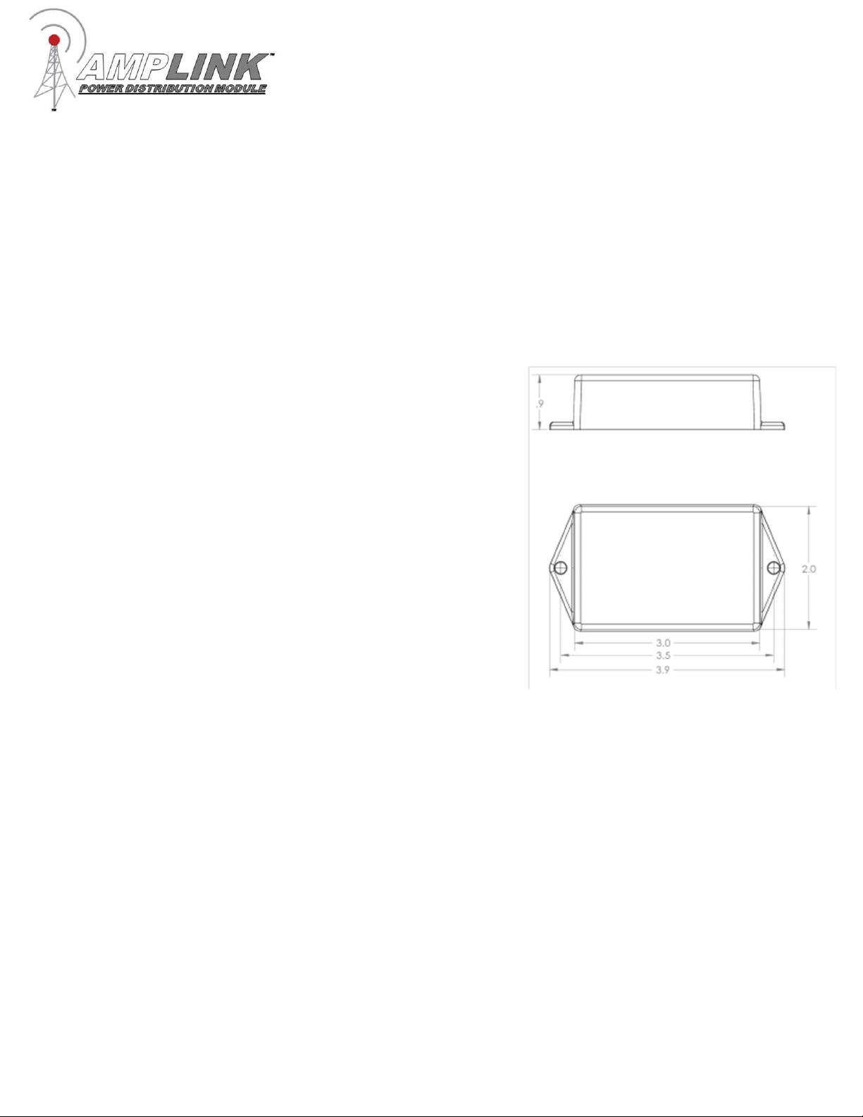
Dimensions: 3.0 x 2.0 x 0.9 in. / 76.2 x 50.8 x 22.9 mm

Page 3 of 12
Device Overview
Red 10 awg main +12V power wire
Connect directly to the positive pole of the vehicle battery. Always connect the + before
connecting ground. For additional protection, a high amperage fuse (not included) can be added
between the Amplink PDM and the battery. Please contact Rowe Electronics for wire gauge
recommendations when extending this wire.
Black 18 awg internal ground wire
Connect directly to the battery ground or suitable ground point like the ground bus cable included.
Connect the Amplink ground (black) wire after connecting the red + to the battery.
Triggers 20 awg input wires (white-T1, purple-T2, yellow-T3)
Connect 1, 2 or 3 triggers to achieve desired functionality. At least one trigger is required to be
activated in order to wake the Amplink device from sleep. These wires are stamped “TRIGGER1”,
“TRIGGER2”, “TRIGGER3”
Outputs 14 awg (white, purple, yellow, pink, green, orange)
Connect these output wires to the +12V input wire of the accessory to be powered. Each output is
stamped with “OUTPUT” and the corresponding circuit number.
Always Live 14 awg wire (red with white stripe)
The always live output, stamped “ALWAYS LIVE”, allows low amperage battery charging
through the Amplink PDM. Please note: There is no monitoring or protection on this always
live circuit. It should be capped or taped off if not being used.
+
12
V to battery
ground to battery
trigger
1
trigger
2
trigger
3
output
1
output
2
output
4
always live
output
6
output
5
output
3

Page 4 of 12
Installation Basics
1. Install the “Amplink PDM” App on a smartphone or tablet
2. Determine a suitable location to mount the Amplink PDM near the battery
3. Connect the Amplink to the battery, red (+) wire first then the black (ground) wire
4. Open the App, wait for it to pair to the Amplink, then set the configurate (See “App Connection
Instructions”)
5. The small green LED light on the Amplink means the Bluetooth signal is being broadcast. If the light
is not on, it will not connect to a mobile device. It will time out after 1 minute if the unit is not triggered
or currently connected to a Bluetooth device.
5. Connect the trigger wires and output wires using the Posi-connectors or other appropriate method
6. Activate the Amplink PDM using the appropriate trigger method
Note: Before completing a full installation of the Amplink, we recommend bench testing to ensure the
setup functions as desired.
Amplink PDM App
The app is designed to be simple and straight to the point. It is intended to be a tool for programming
and monitoring the output status only. The app has three main pages:
Outputs – shows the status of each of the 6 outputs and access to the Output Configuration page
Output Configuration – Allows for the configuration of outputs
Triggers – access each of the 3 input triggers to setup the behavior
Never interact with the app while operating a vehicle.
Page 5 of 12
App Connection Instructions
Note: Pictures in this section are for reference only. Screen and connection steps may differ slightly
based on the version of iOS or Android installed on the mobile device used for connecting.
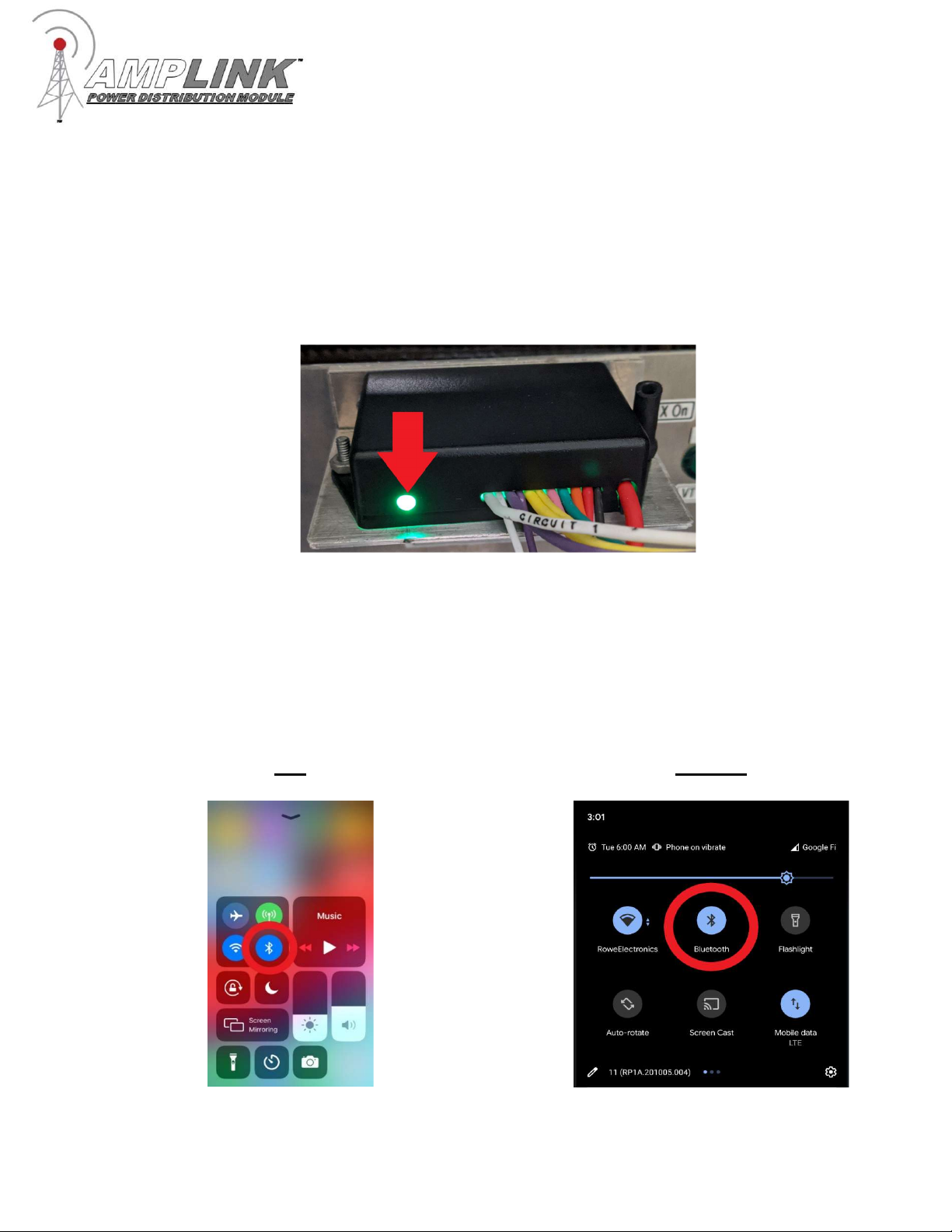
1. Ensure the Amplink PDM is powered on as indicated by the green LED light.
2. Bluetooth on mobile device must be on for the app to operate. DO NOT connect to the Amplink from
within the mobile device’s settings, this will block the app from being able to pair with the Amplink
device.
iOS Android
Page 6 of 12
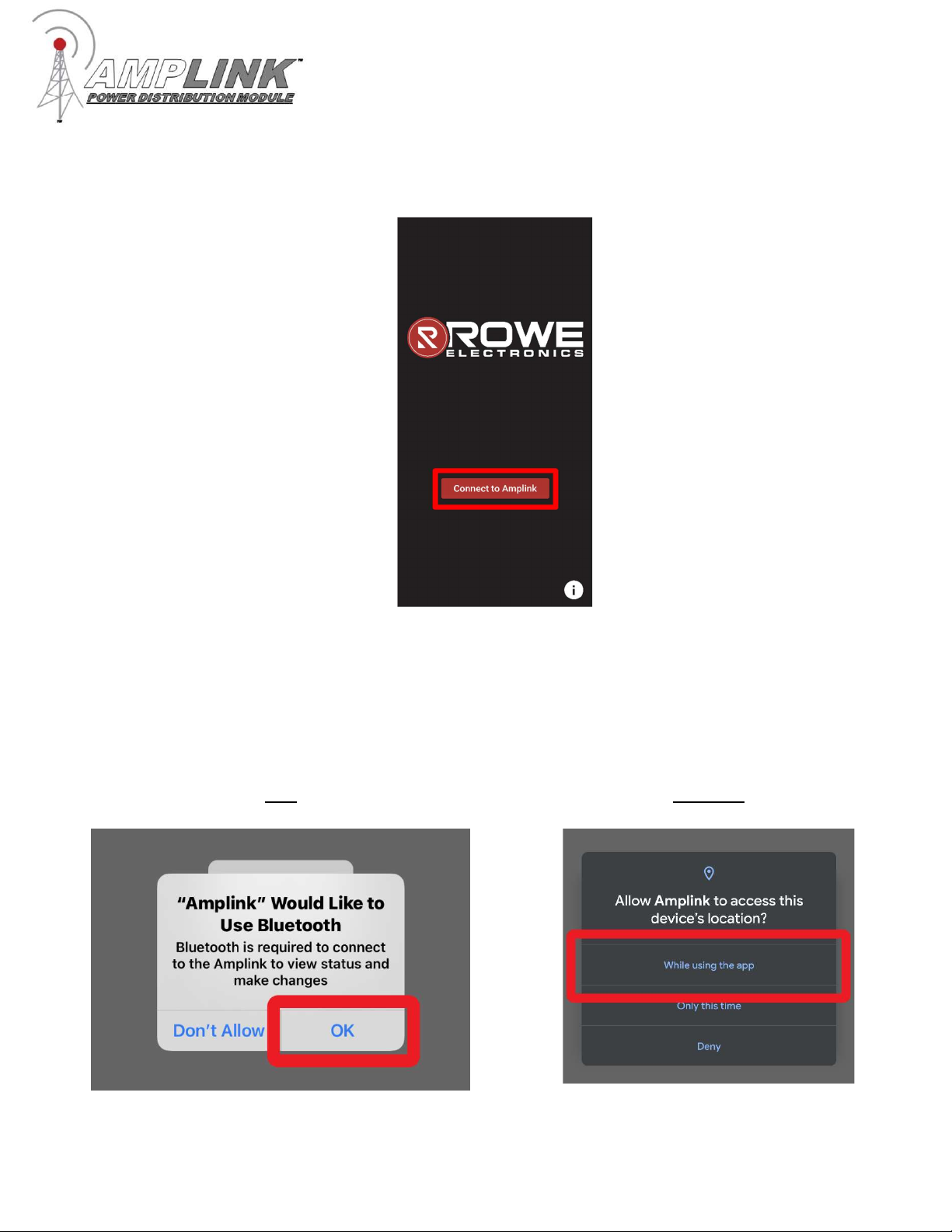
3. Open the Amplink app and tap “Connect to Amplink”.
4. The Android app may ask for location permissions, click “Allow” or “While using the app”. The iOS app
may ask for Bluetooth permissions, click “Allow” or “OK”. These permissions are needed to connect to
the Amplink device.
iOS Android
Page 7 of 12
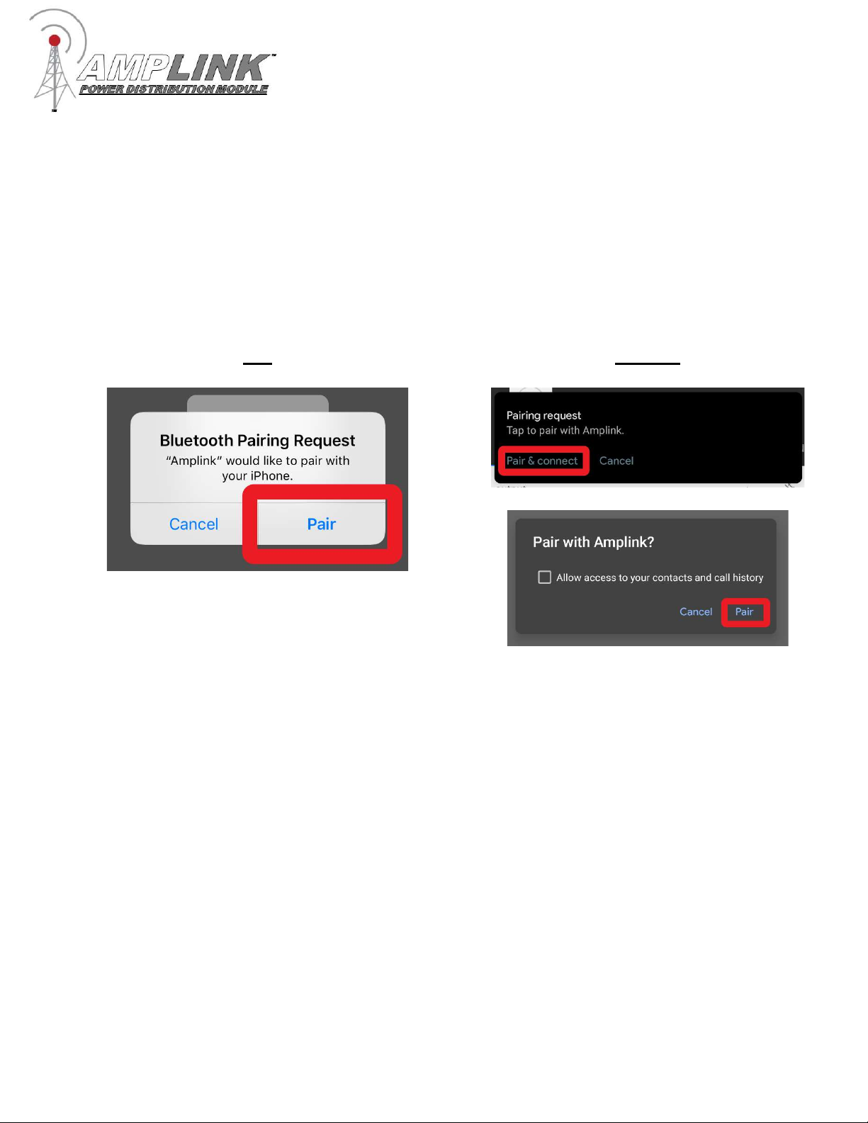
5. Wait for the app to find nearby Amplink devices. If no Amplinks are found, make sure the Amplink is
powered on and the green LED light is lit. From the list, select the Amplink device to connect to. The
app will then begin trying to connect to the Amplink device. The iOS app will ask to pair to the Amplink
device, click “Pair”. The Android app could have a notification labeled “Pairing Request”, click “Pair &
Connect”. This will display a pop-up labeled “Pair with Amplink”, Click “Pair”.
iOS Android

Page 8 of 12
App Connection Troubleshooting
If a “Bluetooth Error” popup appears, to make sure the mobile device’s Bluetooth is on. If the
mobile device is running Android, makes sure the Amplink app has location permissions (Settings
-> Apps & Notifications-> Amplink -> Permissions -> Location -> Allow). If the mobile device is
running iOS, make sure Bluetooth permissions are enabled (Settings -> Scroll down to “Amplink” -
> then enable Bluetooth permissions). Then repeat the pairing process.
If connection is lost. Make sure the Amplink is powered on and the green LED light is lit. Then
repeat the pairing process.
If, upon pairing request, cancel is pressed or the pop-up is missed, click “Cancel” and repeat the
pairing process.
If the Amplink is connected in the Bluetooth settings but the app cannot find the device, forget the
Amplink device. When using iOS go to Bluetooth settings click the blue “i” within the circle next to
“Amplink” then select “Forget this device”. When using Android go to Bluetooth settings and click
the gear icon and select “Forget”. Then open the app back up and try again.
If the Amplink device has a serial number less or equal to 56027415 and the app is stuck on the
“Connecting to Amplink” page and no pairing request has appeared. The Amplink device may
have reached the max number of pairable mobile devices. To fix this the Amplink device will need
to be sent in for reprogramming, after which there will no longer be a limit on the number of
devices that can pair with Amplink device. There is no charge for this upgrade. Please give us a
call or email us to make sure this is the issue. If this is found to be the problem an RMA will be
issued along with shipping instructions.
Phone: 515-981-5504, Email: info@rowe-electronics.com
Note: Amplinks with a serial number greater than 56027415 will not have this issue.
Page 9 of 12
App Overview
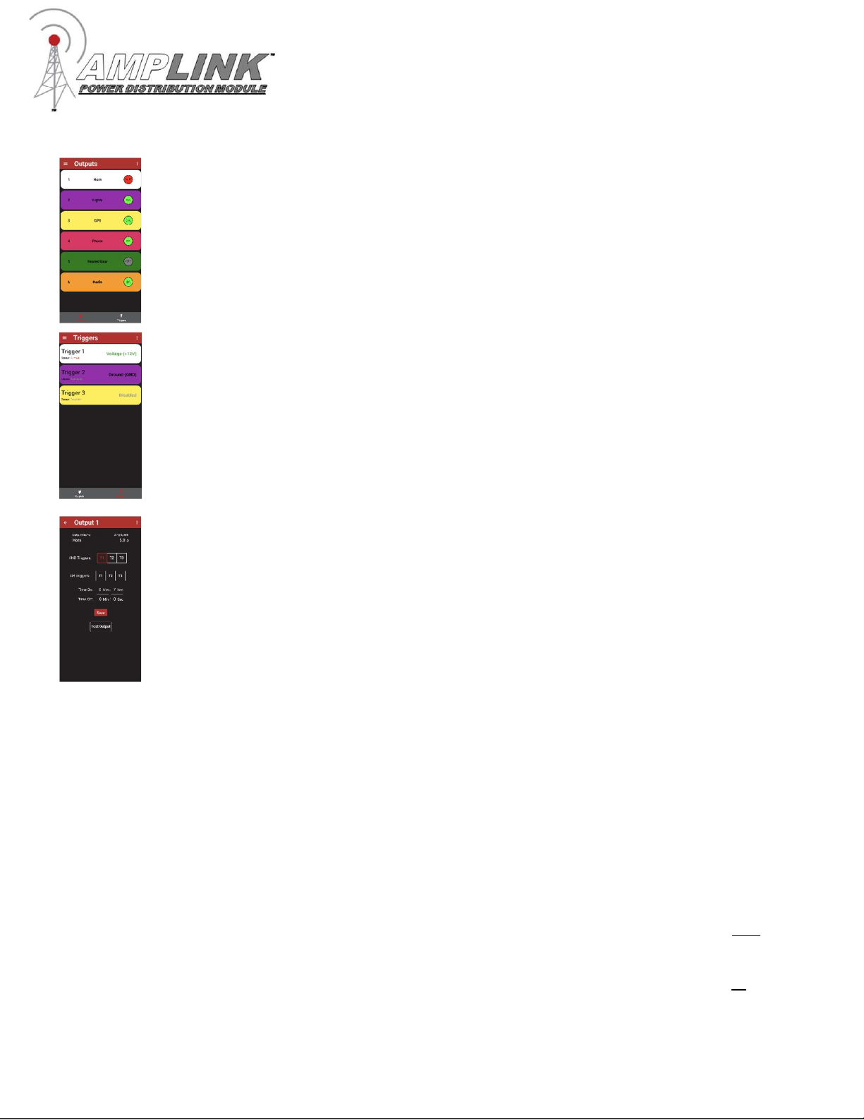
Output The output page allows for monitoring the current state of the outputs of Amplink
device. The colored bars match the wire color of the corresponding output on Amplink
PDM. The output status is indicated by either a green dot for ON, red dot for FAULT, or
gray dot for OFF. By tapping an output, the Output Configuration page will appear.
Triggers Input triggers are configured from the triggers page. At least one trigger must be
active and set to “Voltage (+12V)” or “Ground (GND).” If using multiple triggers, select the
input signal it will respond to, choose either “Voltage (+12V)” or “Ground (GND)”. Any
unused triggers should be set to disabled. The triggers have three states “Activated”
meaning the trigger has detected either Voltage or Ground, “Armed” meaning the trigger is
waiting for the desired voltage, or “Disabled” meaning the trigger will never be activated.
Output Configuration The configuration page is used to configure output settings
including: output name, amperage limit, time on, time off, trigger logic (and/or). Tap “Save”
to save the configuration to the Amplink. Tapping the back button will discard changes and
exit the configuration screen.
Name - tap the field to open the keyboard.
Amp limit - tap the field and enter the current limit
.
AND Triggers – tap and select the triggers
OR Triggers – tap and select the triggers
Time On and Time Off – enter the time before the output turns on or off
Test – tap to turn Output on or off, exiting the screen will turn off the output.
Trigger logic examples:
To setup all outputs to respond to an ignition trigger, select T1 in the “OR Triggers”
and leave “And Triggers” set to None.
Other Examples:
AND Trigger set to T1,T2 – the output will turn on when both Trigger 1 and Trigger 2
are activated.
OR Trigger set to T1,T2 – the output will turn on when either Trigger 1 or Trigger 2 is
activated.
Page 10 of 12
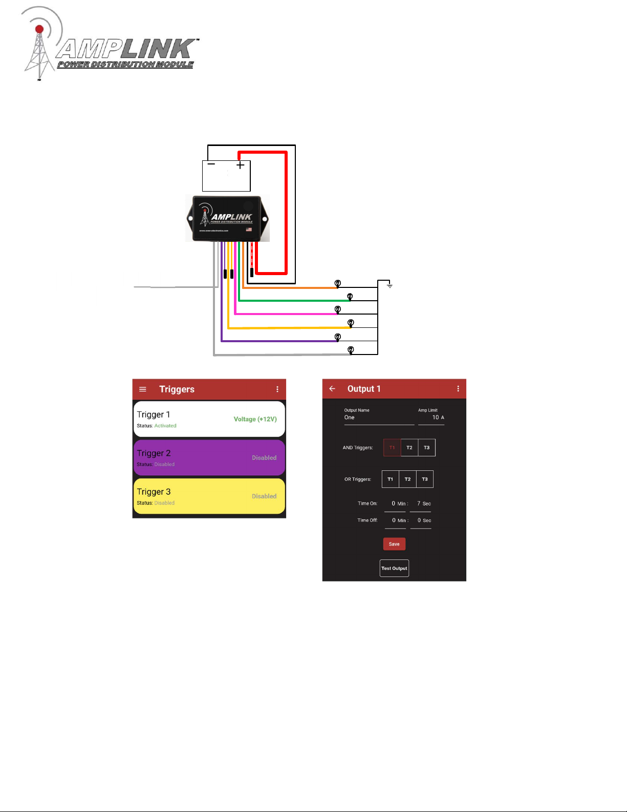
Wiring and App Setup Example 1
Ignition trigger only. Outputs 1-6 will turn on and off with ignition. Connect the
Red (+) wire to the battery before the black ground.
Configure the Amplink PDM using the App
Configure the trigger page as
shown, then proceed to
configure the outputs
In the Output Configuration
page set the triggers as shown.
The output name, amp limit
and delay times can be set
from this page. When finished
tap the “Save” button and
proceed to the next output. Set
the triggers as shown on each
output
12
V
battery
Ignition switched
+
12
V source
Indice


