Andover Controls ACC EMX 156 Manuale utente

Copyright © 1992 Andover Controls Corporation, 300 Brickstone Square, Andover, MA 01810 All Rights Reserved.
Click for EMX Menu
Your warranty is effective for 18 months starting on the
date the system is shipped.
Before You Begin
You can connect one or more EMXmodules to most Infinet
controllers that have an expansion port. The particular con-
trollers are covered in the ACC EMX ModulesConfiguration
Guide(also enclosed with this product).The configuration
guide also tells how many inputs and outputs are allowed for
any particular controller. Before you proceed, be sure the
controller allows modules and the number and type of mod-
ules you plan to use.
Warning
Be sure wiring and installations comply with local, state,
and national electrical codes.
Figure 1 shows the EMX 156 module.
Figure 1. The EMX 156 Module
Dimensions
Each EMX 156 module is approximately 3.75×4.25×1.5in.
EMX156
BOARD OUTPUT
A
OVERRIDE
A B
OUTPUT
B
LOAD
A
LOAD
B
DATE
1
2
UL
INPUTS
VOLTS 24V
AMPS 36MA
OUTPUTS
VOLTS 240V
AMPS 3.5A LISTED
ACCESSORY EQUIPMENT
58B2
FOR USE WITH
SCX LCX AND TCX UNITS,
24VDC
CLASS
II
AUTO OFF ON AUTOOFFON
R
Power Requirements
The EMX 156 consumes up to 32mA at 24 VDC.
Forpowerrequirementswheninstalling multiplemodules
see the ACC EMXModules Configuration Guide.
Environmental Requirements
The EMX 156 operates in the same environment that any
Infinetcontroller operates in.
Output Characteristics
The two outputs are Form A (SPST) AC outputs with
override and feed back detection.
All outputs may be programmed or set with manual over-
ride switches.
The Form Aoutputs are rated for 3A at 24–280 VAC.
Install the EMX 156
1. Unpack
Becareful when unpacking the unitorunits to not damage
the packaging material—you must reuse it if you ship the
product back for repair.
2. Connect to the Infinet Controller
Connect the module to the Infinetcontroller as follows:
Caution
Be sure you disconnect the Infinet controller’s AC power
source before you connect any modules.
1.Look at the bottom panel of your Infinetcontroller. On
that panel is an expansion port in approximately the
center of the panel.
2.Look at the EMX 156 module. Notice that it has a
connector on the top and on the bottom. Plug the top
connector into the Infinetcontroller.
ACC EMX 156
Installation Guide
Order No. 30-3001-349
Version 1.3
www.PDF-Zoo.com

Click for EMX Menu
EMX156InstallationGuide 2
3.If you are connecting more than one EMX 156 module
to your Infinet controller, connect the second one to the
bottom of the first.
4.Set the BOARD switch(upper right) to 1on the firstEMX
156,andtheBOARDswitch to2onthesecond EMX156.
If you do not plan to connect more than one EMX 156
module, set the BOARD switch to 1.
Never set two modules of the same model number to the
same board number.
3. Connect the External Power Supply
(if necessary)
If you are installing multiple modules, you may need an
external power supply. To determine what you need, refer
to the ACC EMX Modules Configuration Guide.
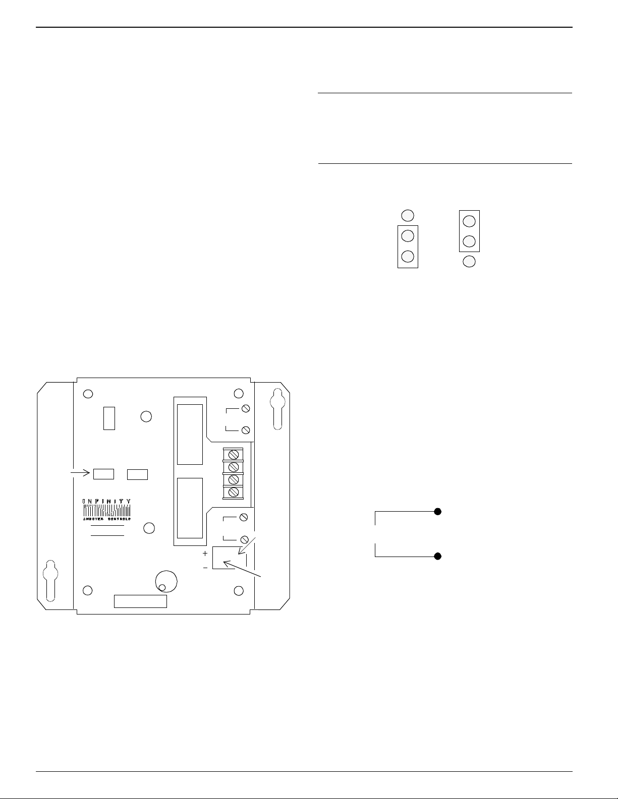
Figure2 shows where youconnect the externalpowersupply
to the 2-pin Berg type connector on the EMX 156.
Figure 2. Location of External Power Connection
and External Power Supply Jumper
4. Reposition Jumper of One Module
The Berg type connector immediately to the left of the ex-
ternal power supply connection has a jumper that you
reposition to indicate you are using external power.
Figure 3 shows the jumper in the two possible positions, one
fortheinternalpower supply,theotherfor theexternal.Move
the jumper to the external power supply position.
Connect
External
Power
Supply
Here
Move
External
Power
Jumper
EMX156
BOARD OUTPUT
A
OVERRIDE
A B
OUTPUT
B
LOAD
A
LOAD
B
DATE
1
2
UL
INPUTS
VOLTS 24V
AMPS 36MA
OUTPUTS
VOLTS 240V
AMPS 3.5A LISTED
ACCESSORY EQUIPMENT
58B2
FOR USE WITH
SCX LCX AND TCX UNITS,
24VDC
CLASS
II
AUTO OFF ON AUTOOFFON
R
Override
Switches
You change the jumper position only on the module or mod-
ules connected to the external power supply, noton any other
modules.
Note
You need to change the jumper position onlyon the mod-
ule(s) actually connectedto an externalpower supply. Never
change the jumper position of other modules.
Figure 3. Jumper Positions for Internal and External
Power Supplies
Each is set to the internal position when you receive it.
Wire the Outputs
You wire the outputs as follows:
1.Slip the appropriate wiresunder the Load Ascrewsand
tighten the screw down on it.
2.Slip the appropriate wiresunder the Load Bscrewsand
tighten the screwsdown on it.
Figure 4 illustrates the wiring for Form Aoutputs.
Figure 4. Wiring Diagram for Form A Outputs
Troubleshoot
If you have problems with the Infinetcontroller after in-
stalling the module, see your Andover Controls
representative for details.
Refer to theEnergyNet and Infinet Configuration Guide
for information on how to troubleshoot network and pow-
er supply problems.
Jumper Position,
External Power
Supply
Jumper Position,
Internal Power
Supply
Load A
www.PDF-Zoo.com

Click for EMX Menu
EMX156InstallationGuide 3
Warning
This equipment has been tested and found to comply
with the limits for a Class A digital device, pursuant to
Part 15 of the FCC Rules. These limits are designed to
provide reasonable protection against harmful interfer-
ence when the equipment is operated in a commercial
environment. This equipment generates, uses, and can
radiate radio frequency energy and, if not installed and
used in accordance with the instructions in this manual,
may cause harmful interference to radio communica-
tions. Operation of this equipment in a residential area
is likely to cause harmful interference in which case the
user will be required to correct the interference at his
own expense.
Note
This digital apparatus does not exceed the Class A lim-
its for radio noise emissions from digital apparatus set
out in the Radio Interference Regulations of the Cana-
dian Department of Communications.
Avis
Le présent appareil numérique n’émet pas de bruits ra-
dioélectriques dépassant les limites applicables aux
appareils numériques de la class A prescrites dans le
Règlementsur lebrouillage radioélectrique édictépar le
ministère des Communications du Canada.
www.PDF-Zoo.com

Click for EMX Menu
EMX156InstallationGuide 4
www.PDF-Zoo.com
Altri manuali Andover Controls Controllori di accesso IP


