Angst+Pfister PFLOW5001 Series Manuale utente

Attention!
Use with caution!
•Please carefully read this manual prior to operating this product.
•Do not open or modify any hardware which may lead to irrecoverable
damage.
•Do not use this product if you suspect any malfunctions or defection.
•Do not use this product for corrosive media or in a strong vibration
environment.
•Use this product according to the specified parameters.
•Only the trained or qualified personnel shall be allowed to perform
product services.
•Be cautious for electrical safety, and even it operates at a low voltage,
any electrical shock might lead to some unexpected damages.
•The gas to be measured should be clean and free of particles, as
particles may be accumulated inside the flow channel
that may result in inaccuracy in metrology, clogging, or other
irrecoverable damage.
•Do not apply for any unknown or non-specified gases that may
damage the product.
2 PFLOW5001-C5001-VA3_1610-21914-0073-E-0823

Table of Contents
1. Overview.................................................................................................. 5
2. Receipt / unpack of the products ................................................................ 6
3. Knowing the products ............................................................................... 7
3.1 Product description.............................................................................................7
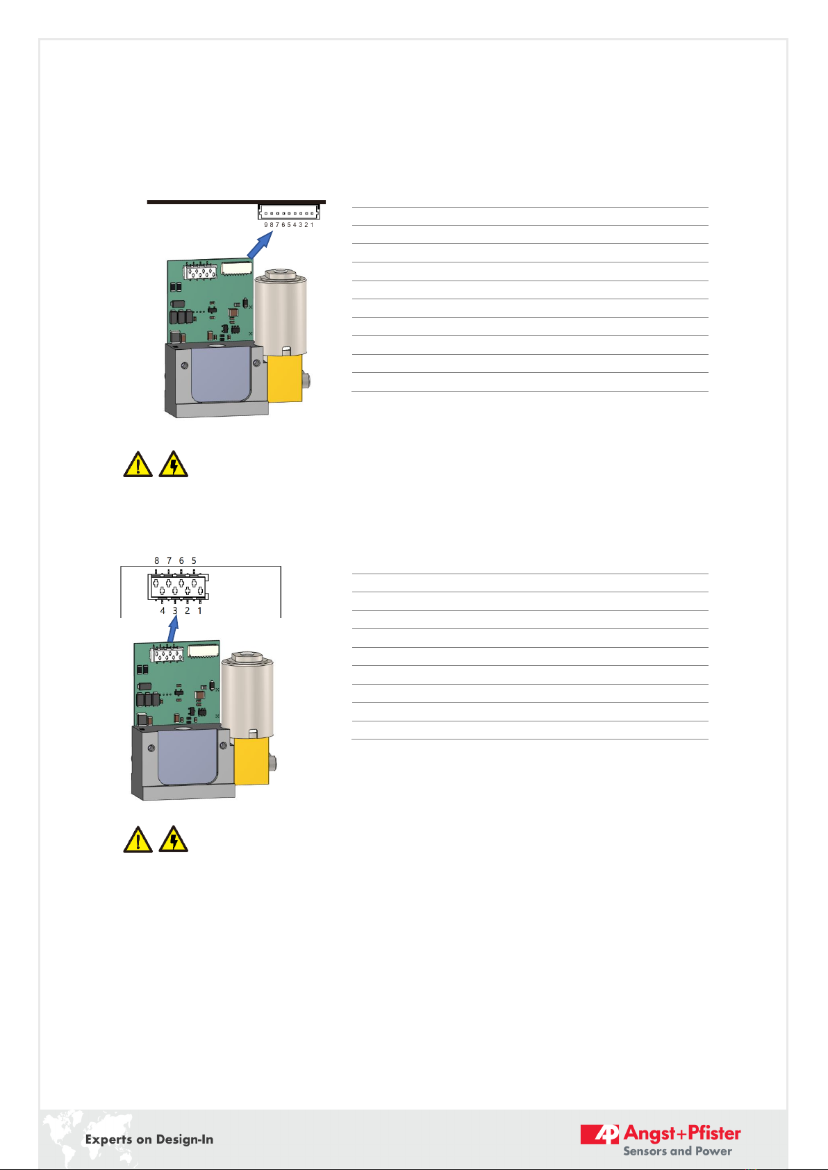
3.2 Power and data pinout description .......................................................................7
3.2.1 PFLOW5001 - RS232 TTL .....................................................................................7
3.2.2 PFLOW5001 - RS232 EIA ......................................................................................8
3.2.3 PFLOW5001 - RS485 Half-duplex .........................................................................8
3.2.4 PFLOW5001 - RS485 Full-duplex ..........................................................................9
3.2.5 PFLOW5001 –I2C ................................................................................................9
3.2.6 PFLOWC5001 - RS232 TTL ................................................................................. 10
3.2.7 PFLOWC5001 - RS232 EIA .................................................................................. 10
3.2.8 PFLOWC5001 - RS485 Half-duplex ..................................................................... 11
3.2.9 PFLOWC5001 - RS485 Full-duplex ...................................................................... 11
3.3 Mechanical dimensions...................................................................................... 13
4. Installation..............................................................................................15
5. Basic operation........................................................................................16
5.1 RS232 communication protocol..........................................................................16
5.1.1 Serial port settings............................................................................................16
5.1.2 Command format..............................................................................................16
5.1.3 Response format...............................................................................................16
5.1.4 Command to read/write variables....................................................................... 17
5.1.5 Read flow rate .................................................................................................. 17
5.1.6 Read serial number ...........................................................................................18
5.1.7 Select input mode .............................................................................................18
5.1.8 Setpoint ...........................................................................................................19
5.1.9 Exhaust value ................................................................................................... 20
5.1.10 Offset calibration ........................................................................................ 20
3 PFLOW5001-C5001-VA3_1610-21914-0073-E-0823

5.1.11 P Gain and D Gain........................................................................................ 20
5.1.12 Firmware version......................................................................................... 21
5.1.13 Filter depth................................................................................................. 21
5.1.14 Gas temperature ......................................................................................... 21
5.1.15 Gas type ..................................................................................................... 21
5.2 RS485 Modbus communication protocol............................................................. 22
5.2.1 Hardware connection ........................................................................................ 22
5.2.2 Communication parameters .............................................................................. 22
5.2.3 Frame............................................................................................................... 23
5.2.4 Function codes.................................................................................................. 23
5.2.5 Registers .......................................................................................................... 23
5.3 I2C communication protocol...............................................................................28
5.3.1 I2C interface connection diagram........................................................................28
5.3.2 I2C interface read/write sequences......................................................................29
5.3.3 I2C interface command description .....................................................................29
5.3.4 CRC checksum calculation ................................................................................. 30
5.4 Analog output and control................................................................................. 31
6. Product selection.....................................................................................32
7. Product performance ...............................................................................33
8. Technical notes for the product performance.............................................34
8.1 Measurement principles .................................................................................... 34
8.2 Precautions for the best performance of the product ........................................... 34
8.2.1 Contamination.................................................................................................. 34
8.2.2 Altitude changes............................................................................................... 34
8.2.3 Excessive humidity or condensation................................................................... 35
8.2.4 Metrology verification ....................................................................................... 35
9. Warranty and Liability..............................................................................36
Appendix I: Document history........................................................................38
4 PFLOW5001-C5001-VA3_1610-21914-0073-E-0823

1. Overview
This manual provides essential information for the operation of the PFLOW5001 / PFLOWC5001
series of gas mass flow sensors for general-purpose gas flow monitor and control applications with
the full-scale mass flow rate from 0.2 to 20 SLPM, and both analog and digital outputs. The product
performance, maintenance, and troubleshooting as well as the information for product order,
technical support, and repair are also included.
PFLOW5001 / PFLOWC5001 are available in the manifold configuration for the mechanical
connections. Optionally they can also be offered with a manifold body with the 4mm one-touch
flexible piping. They can be applied to medical equipment and instrumentation applications. The
series covers a wide dynamic flow range with a working pressure rating of up to 1.0 MPa (10 bar or
150 PSI), and a compensated temperature ranging from -5 to 50°C.
The sensing elements are manufactured with MEMS (micro-electro-mechanical systems) thermal
mass flow sensing technologies that measure the calorimetry and diffusivity of the flow medium.
The sensor surface is passivated with silicon nitride ceramic materials together with water/oilproof
nano-coating for performance and reliability. Compared to the conventional calorimetric flow
sensing technology, this unique sensing approach offers better linearity, removes gas sensitivity for
gases with similar thermal diffusivities, and improves temperature performance. It can also auto-
recognize pre-programmed gases with significant differences in thermal diffusivity. It is the first of a
kind in the industry that senses the mass flow with multiple gases without a manual gas conversion
factor. As such, it ensures high precision for gas measurements with air calibration.
5 PFLOW5001-C5001-VA3_1610-21914-0073-E-0823

2. Receipt / unpack of the products
Upon receipt of the products, please check the packing box before dismantling the packing materials.
Ensure no damages during shipping. If any abnormality is observed, please contact and notify the
carrier who shipped the product and inform the distributors or sales representatives if the order is
not placed directly with the manufacturer; otherwise, the manufacturer should be informed. Please
refer to the return and repair section in this manual for any further actions.
If the packing box is intact, proceed to open the packing box, and you shall find the product (either
the sensor formality per the actual order), together with the power and data cable if the order is
included.
Please immediately check the integrity of the product and the power and data cable; if any
abnormality is identified, please notify the distributor/sales representative or manufacturer as soon
as possible. If any defects are confirmed, an exchange shall be arranged immediately via the original
sales channel. This user manual shall also be included in the packing box or via an online link for an
electronic version your sales agent should send. In most cases, this manual shall be made available
to the customer before the actual order.
6 PFLOW5001-C5001-VA3_1610-21914-0073-E-0823

3. Knowing the products
3.1 Product description
Figure 3.1: PFLOW5001 / PFLOWC5001 parts description
3.2 Power and data pinout description
3.2.1 PFLOW5001 - RS232 TTL
The electrical interface is a JST-SM09B-SRSS-TB connector (9 pole).
DO NOT connect or disconnect the cable when the external power is on!! It may damage
the electronic chipsets of the product!
Pin
Definition
1
Power, 8 ~ 24 Vdc
2
Power common / Ground
3
RS232 TTL: RxD
4
RS232 TTL: TxD
5
Analog: Ground
6
N.C.
7
Analog: Flow output 0 ~ 5 Vdc
8
N.C.
9
N.C.
Control
electronics
Data/power socket
Control valve
Installation
mounting port.
Note: The manifold base port size should not be smaller than those of the flow ports on the
product.
Manifold flow
ports
Dowel pin port
Controller
body
Flow channel
in/outlet
Top view
7 PFLOW5001-C5001-VA3_1610-21914-0073-E-0823

3.2.2 PFLOW5001 - RS232 EIA
The electrical interface is a Micromatch (8 pole).
DO NOT connect or disconnect the cable when the external power is on!! It may damage
the electronic chipsets of the product!
3.2.3 PFLOW5001 - RS485 Half-duplex
The electrical interface is a Micromatch (8 pole).
DO NOT connect or disconnect the cable when the external power is on!! It may damage
the electronic chipsets of the product!
Pin
Definition
1
Power, 8 ~ 24 Vdc
2
Power common / Ground
3
RS232 EIA: RxD
4
RS232 EIA: TxD
5
Analog: Ground
6
Analog: Flow output 0 ~ 5 Vdc
7
N.C.
8
N.C.
Pin
Definition
1
Power, 8 ~ 24 Vdc
2
Power common / Ground
3
RS485 Half-duplex: A (+)
4
RS485 Half-duplex: B (-)
5
N.C.
6
N.C.
7
N.C.
8
N.C.
8 PFLOW5001-C5001-VA3_1610-21914-0073-E-0823

3.2.4 PFLOW5001 - RS485 Full-duplex
The electrical interface is a Micromatch (8 pole).
DO NOT connect or disconnect the cable when the external power is on!! It may damage
the electronic chipsets of the product!
3.2.5 PFLOW5001 –I2C
The electrical interface is a Micromatch (8 pole).
DO NOT connect or disconnect the cable when the external power is on!! It may damage
the electronic chipsets of the product!
Pin
Definition
1
Power, 8 ~ 24 Vdc
2
Power common / Ground
3
RS485 Full-duplex: R (+)
4
RS485 Full-duplex: R (-)
5
N.C.
6
RS485 Full-duplex: T (-)
7
RS485 Full-duplex: T (+)
8
N.C.
Pin
Definition
1
Power, 8 ~ 24 Vdc
2
Power common / Ground
3
I2C: SCL
4
I2C: SDA
5
Analog: Ground
6
Analog: Flow output 0 ~ 5 Vdc
7
N.C.
8
N.C.
9 PFLOW5001-C5001-VA3_1610-21914-0073-E-0823

3.2.6 PFLOWC5001 - RS232 TTL
The electrical interface is a JST-SM09B-SRSS-TB connector (9 pole).
DO NOT connect or disconnect the cable when the external power is on!! It may damage
the electronic chipsets of the product!
3.2.7 PFLOWC5001 - RS232 EIA
The electrical interface is a Micromatch (8 pole).
DO NOT connect or disconnect the cable when the external power is on!! It may damage
the electronic chipsets of the product!
Pin
Definition
1
Power, 8 ~ 24 Vdc
2
Power common / Ground
3
RS232 TTL: RxD
4
RS232 TTL: TxD
5
Analog: Ground
6
Analog: PID output 0 ~ 5 Vdc
7
Analog: Flow output 0 ~ 5 Vdc
8
Analog: Set point 0 ~ 5 Vdc
9
Analog: Valve override 0 ~ 5 Vdc
Pin
Definition
1
Power, 8 ~ 24 Vdc
2
Power common / Ground
3
RS232 EIA: RxD
4
RS232 EIA: TxD
5
Analog: Ground
6
Analog: Flow output 0 ~ 5 Vdc
7
Analog: Set point 0 ~ 5 Vdc
8
Analog: Valve override 0 ~ 5 Vdc
Top view
10 PFLOW5001-C5001-VA3_1610-21914-0073-E-0823
Altri manuali per PFLOW5001 Series
1
Questo manuale è adatto per i seguenti modelli
1
Indice


