AntennaWorks 8877 Manuale utente
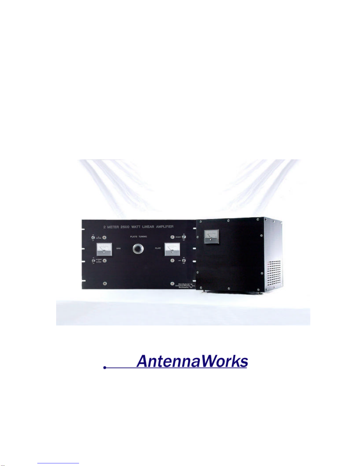
2 Meter 144 to 148 MHz
2500 Watt 8877 Amplifier
Users Guide
1301 Crooked mile Ct.
Placerville, Ca 95815
(916) 765-5811
Revision 1.01, 3/24/00

2
Table of Contents
TABLE OF CONTENTS ..................................................................................2
CHAPTER 1…………………………………………… SAFETY FIRST!........3
CHAPTER 2. ………………………………………….. INTRODUCTION.......4
CHAPTER 3. ……………………….…………………….. PARTS LIST........5
CHAPTER 4. …………………. ASSEMBLY TOOLS AND REQUIREMENTS......6
CHAPTER 5. ………………………………………………….CAUTION .....7
CHAPTER 6. …… CONNECTING THE POWER SUPPLY TO THE AMPLIFIER......8
CHAPTER 7. …………CONNECTING THE HIGH VOLTAGE YELLOW WIRE ..10
CHAPTER 8. ……………………….. CONNECTING THE 240 VOLT PLUG...11
CHAPTER 9. …………………………… RE-CHECK ALL CONNECTIONS ...12
CHAPTER 10. ………………………………. HOOK UP THE RF CABLES ...13
CHAPTER 11. ………………………………. COAX RELAY SWITCHING....14
CHAPTER 12. …………………………………... INSTALLING THE TUBE...15
CHAPTER 13. ……………………… TUNE AND OPERATION PROCEDURE..16

3
Chapter 1. Safety First!
~HIGH VOLTAGE!
~You can be killed so follow safety tips!
~Verify there is no voltage present before working with the amplifier.
~When in doubt do not touch it.
~Install unit safely in a 19-inch rack.
~Never open the amp or supply when it is turned on or plugged in.
~Wait for capacitor bank to discharge before working on the unit.
~Check power cords and high voltage lines often for damage.
~Enjoy your amplifier and always be cautious.
4
Chapter 2. Introduction
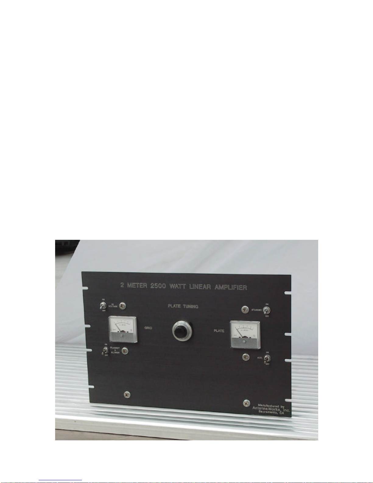
Welcome to world class VHF operation using the Antenna Works 2 meter
144 to 148 MHz 2500 watt 8877 amplifier. This amplifier has been adapted
from the original W6PO 8877 Eimac Amateur Service Newsletter - W6SAI
1971. Many years of design improvements has brought this amplifier to
what it is today. This is a high efficiency and high power amplifier for the
VHF enthusiast.
We here at AntennaWorks wish you good contacts using the amplifier for
your EME or terrestrial VHF contacts. Using the Antenna Works VHF
amplifier will enable you to achieve extreme distant contacts. We know you
will be thrilled by its performance.

5
Chapter 3. Parts List
AntennaWorks 2 Meter 144 to 148 MHz 2500 Watt 8877 Amplifier:
q2 meter 144 to 148 MHz 2500 watt 8877 amplifier
qAntennaWorks 2 Meter Amplifier power supply.
qConduit for power supply connection
qHigh voltage connector
OPTIONS:
Relays:
qRF Relays
Meters:
qSurelite
qSimpson
Tube:
qEimac 3cx1500A7 S/N_________________ Date
Code_________________
Other:
q_________________________________________________________
q_________________________________________________________
q_________________________________________________________
q_________________________________________________________
Signed ________________________________ Date _______________
QC ___________________________________ Date _______________

6
Chapter 4. Assembly Tools and Requirements
The following is needed to assemble the Antenna Works amplifier.
Phillips #2 Screwdriver
Small flat Head Screwdriver
Wire Cutter
Wire Stripper
Solder
Solder Iron

7
Chapter 5. Caution
If you are uncomfortable or unknowledgeable about high voltage safety and
assembly, seek qualified personnel to assemble the amplifier for you. Do not
attempt assembly without proper knowledge.

8
Chapter 6. Connecting the Power Supply to the Amplifier
If you are going to use the gray conduit to go from the supply to the amp you
must put all wires including the Yellow high voltage wire through the
conduit before you start this section. Fasten the gray conduit from the power
supply to the fan and feed all wires including the Yellow high voltage wire
out the fan.
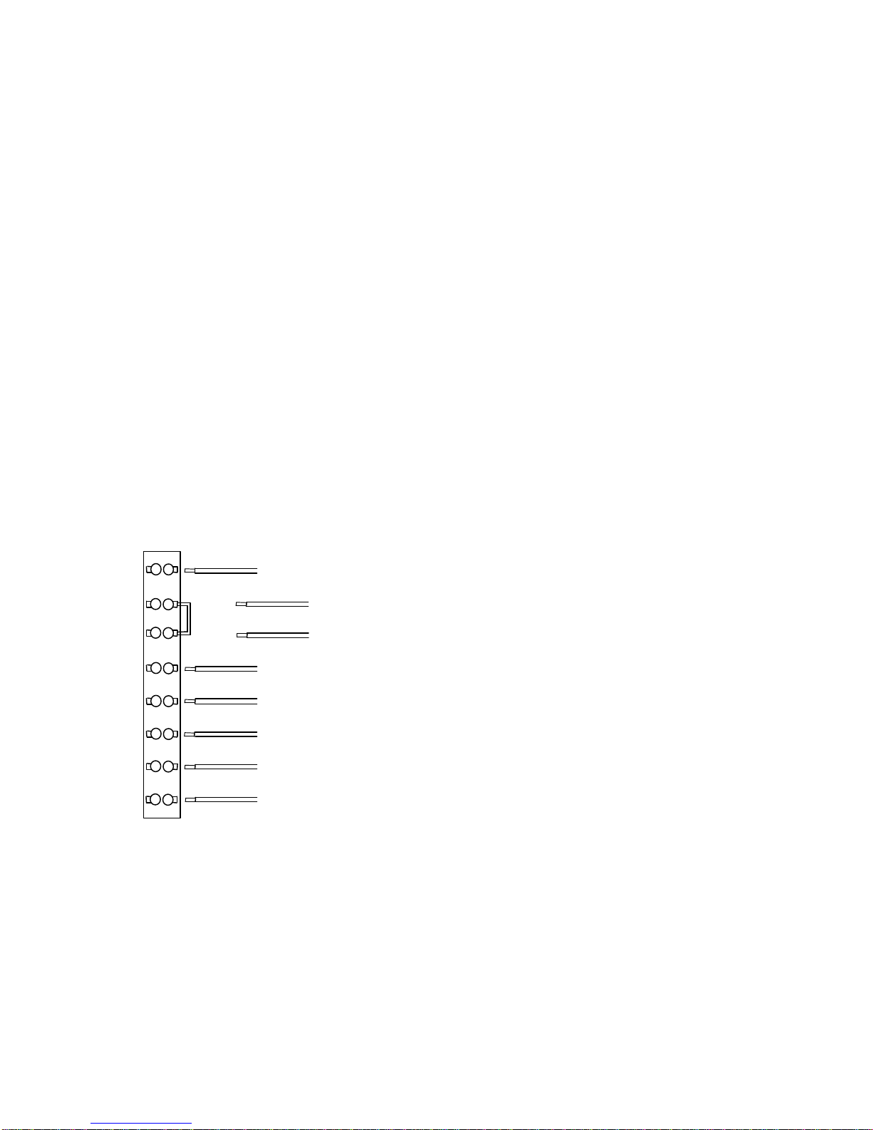
Hooking up amp to supply is easy as 1 to 8. The terminal strip with 8
positions is located on the left rear of the RF decks left side looking at it
from the front. Number the positions 1 through 8 from top to bottom. Refer
to figure 1.
Please start with position no.1 at the top of the terminal strip. The power
supply has a purple wire. This is chassis ground to chassis ground. Strip off
3/16” of insulation from the end of the wire. Hook the purple wire to
position no. 1 Use the flat head screwdriver to tighten the terminal screw
holding the wire.
Look at position nos. 2 and. 3. These are your PTT. 12 VDC are present
here. Short these together to put the amp in the TX mode. To add user
control of the PPT remove the jumper from position no. 2 and 3 and add
your own control wires.
Look at position nos. 4 and 5. These are a pair connected directly to the
front panel of the amp. The High Voltage Turn on Switch is the only place
the brown and orange wires go. Strip off 3/16” of insulation from the end of
each wire. Connect the brown wire to position 4 and the orange wire to
position 5. This allows the high voltage to get turned on after a 90-second
filament and fan warm-up time.
Look at position 6. CAUTION: 6 is red, it is hot 120 VAC, and goes to the
fan and filament switch. It is live all the time and can shock you. Strip off
3/16” of insulation from the end of the wire. Connect the red wire to position
6.
Look at position 7. 7 is green and is the 120-volt return as well as chassis
ground. Strip off 3/16” of insulation from the end of the wire. Connect the
green wire to position no. 7.
9
Look at position 8. 8 is black and is the return. There will only be a low DC
voltage here due to the bias configuration, but a good solid connection is
most important here. Strip off 3/16” of insulation from the end of the wire.
Connect the black wire to position no. 8.
Check your connections:
1 purple = ground
2 and 3 together = PTT
4 brown and 5 orange = High Voltage turn on (120 VAC here).
6 red and 7 green = 120 VAC to run fan and filament.
8 black = b-return.
Re-torque each position of the terminal strip.
1Purple (GND)
2(PPT User Supplied)
3(PPT User Supplied)
4Brown (HV Switch)
5Orange (HV Switch)
6Red (120 VAC)
7Green (120 VAC Return)
8Black (B- Return)
Figure 1. 8 position terminal strip

10
Chapter 7. Connecting the High Voltage Yellow
Wire
If using the gray conduit, you can fasten the gray conduit from the power
supply to the fan and feed the Yellow high voltage wire through the fan to its
high voltage connector using the high voltage connector supplied.
To connect the high voltage yellow wire to the amplifier, strip off 1.25
inches of insulation from the end of the yellow wire from the supply.
Solder on the red high voltage connector. This is the 4,000 VDC that
supplies the RF deck. Connect the red high voltage connector to the RF
deck.
Do not over tighten.
If you see any bare wire during this process, start over.
Think safe and hide the wires.
Indice


