Antex electronics SX-34 Manuale utente

SX-5e SX-6
SX-34 SX-36
Digital Audio Adapter
User's Manual
September 17, 1999
Rev. E
ANTEX ELECTRONICS CORPORATION
1125 W. 190th STREET
GARDENA, CALIFORNIA 90248
www.antex.com
Toll Free: 1-800-338-4231
Fax: 310-532-8509
9000-2351-7006

Declaration of Conformity
Standards to which Conformity is Declared:
EN55022 (Class A) 1994, EN 50082-1 1992
This equipment has been verified to comply with the limits for
a class A computing device, pursuant to FCC Rules. In order
to maintain compliance with FCC regulations, shielded cables
must be used with this equipment. Operation with non-
approved equipment or unshielded cables is likely to result in
interference to radio and TV reception. The user is cautioned
that changes and modifications made to the equipment without
the approval of the manufacturer could void the user's author-
ity to operate this equipment.

TABLE OF CONTENTS
INTRODUCTION......................................................................1
CARD INSTALLATION.............................................................1
JUMPER SETTINGS & CONNECTIONS......................2
I/O ADDRESSES AND INTERRUPTS..........................3
MAKING CONNECTIONS TO THE CARD...............................3
SX-35/36 CONNECTOR DESCRIPTION .................................5
SX-34 CONNECTOR DESCRIPTION......................................8
SX-6 CONNECTOR DESCRIPTION........................................11
SX-5e CONNECTOR DESCRIPTION......................................13
BALANCED AND UNBALANCED SIGNALS............................13
IMPEDANCE AND SIGNAL LEVELS .......................................14
PLAYBACK AND RECORD DEVICES .....................................15
COMPRESSION, DATA RATES, AND NETWORKS ...............16
ISO/MPEG-1 BITRATES..........................................................17
DRIVER INSTALLATION..........................................................19
WINDOWS 95 ..............................................................19
Setup Tips (Upgrade Driver, WIN 95) ...........................19
Setup Tips (Upgrade Driver, WIN 98) ...........................20
WINDOWS NT..............................................................21
ANTEX APPLICATION SOFTWARE INSTALLATION .............22
USING WINDOWS DEMONSTRATION SOFTWARE .............23
INSTALLING AND USING MULTIPLE CARDS IN A SYSTEM.27
DUAL DEVICE OPERATION....................................................27
MIXER AND BLOCK DIAGRAMS.............................................28
SX-36 MIXER AND BLOCK DIAGRAM.........................29

SX-34 MIXER AND BLOCK DIAGRAM.........................34
SX-6 MIXER AND BLOCK DIAGRAM...........................36
SX-5e MIXER AND BLOCK DIAGRAM.........................39
ANTEX METER........................................................................42
TROUBLESHOOTING .............................................................46
TECHNICAL/ORDERING INFORMATION: ..............................49
APPENDIX...............................................................................50
Connectors for Male Headers .......................................50
Terms ...........................................................................50
Specifications................................................................52
About Digital Audio .......................................................54

FIGURES
Figure 1. SX-5e,6,34,35 & SX-36 Jumper Settings...................2
Figure 2. SX-35/36 Connections..............................................5
Figure 3. SX-34 Connections...................................................8
Figure 4. SX-6 Connections.....................................................11
Figure 5. Antex Demo Program...............................................23
Figure 6. MPEG Bitrates..........................................................24
Figure 7. File Open Dialog Box................................................25
Figure 8. Auto Repeat .............................................................26
Figure 9. SX-36 Mixer..............................................................32
Figure 10. SX-36 Block Diagram.............................................33
Figure 11. SX-34 Mixer............................................................34
Figure 12. SX-34 Block Diagram.............................................35
Figure 13. SX-6 Mixer..............................................................37
Figure 14. SX-6 Block Diagram...............................................38
Figure 15. SX-5e Mixer............................................................39
Figure 16. SX-5e Block Diagram.............................................41
Figure 18. Antex Meter pull-down menu..................................43
Figure 19. Antex Meter options................................................44
Figure 20. Analog-to-Digital.....................................................56
Figure 21. Digital-to-Analog.....................................................57

1
INTRODUCTION
The Antex SX-5e, SX-6, SX-34 and SX-36 family of cards are ISA
bus audio “add-in” cards for the PC. They all incorporate DSP’s
(Digital Signal Processors), which allow the cards to do a variety
of audio formats. (MPEG, PCM16, MSADPCM, etc.) All cards are
dual device, which means they can operate on 2 hard drive files at
the same time. These cards operate at several fixed standard
sample rates: 8, 11.025, 16, 22.05, 32, 44.1, and 48 KHz. The
SX-5e and SX-6 are playback only cards, and the SX-34 and SX-
36 have playback and record capability. The SX-5e and SX-34
have unbalanced analog I/O and the SX-6 and SX-36 have bal-
anced analog I/O. Up to 4 cards may be installed into one com-
puter.
Software is provided for Win95/98, and WinNT. Software in-
cludes the “driver”, the Antex Demo application, Antex Mixer ap-
plication, and Antex VU Meter application. Contact Antex Techni-
cal Support or visit the Antex website (www.antex.com), for infor-
mation about DOS or Windows 3.11 drivers, or the Software De-
veloper’s Kit (SDK).
CARD INSTALLATION
Make sure the main power to your computer is OFF. You will
need a 16 bit/AT slot. If you are unfamiliar with the internal design
of your computer see its "Guide to Operations" manual for step by
step installation procedures. To avoid damaging the board or
your computer with static electricity:
1. Touch the metal of your computer chassis first to discharge
the static electricity from yourself before opening the antistatic
bag the Antex Card is packaged in.
2. Move around as little as possible. Don’t shuffle your feet on
carpet or move around in your chair.
3. Handle the card by the bracket and the edges. Try not to
touch the gold fingers or any of the parts on the board.

2
Set the board number with jumpers as shown below. If only one
board is being used, leave the jumpers off (sets to board number
one). When using more than one card in a computer, each board
must be given a different number by setting the jumpers differ-
ently on each card. Any model Antex Card may be used with any
other model Antex Card. All model Antex Cards use the same
jumper arrangement to set the board number.
JUMPER SETTINGS & CONNECTIONS
Top View
Board 1 Board 2 Board 3 Board 4
Covered by jumper
J1
SX-5e/6/34
35/36
2
14
32
14
3
2
14
32
14
3
Figure 1. SX-5e,6,34,35 & SX-36 Jumper Settings
The jumpers are oriented vertically so that they may be easily
changed without having to remove the card from the computer
slot if they should need to be changed later. These jumpers only
set the board number, allowing for more than one board in a com-
puter. They do not set interrupts.

3
I/O ADDRESSES AND INTERRUPTS
SX-5e, 6, 34, 35 & 36 I/O addresses and interrupts are software
selectable. The valid I/O addresses are:
180h, 220h, 280h, 300h, 320h and 380h
The valid interrupts are:
2, 3, 4, 5, 10, 11 and 12
Note that interrupts 3 and 4 are normally used by the computer’s
COM ports and will not be available. The interrupt and I/O ad-
dresses are selected at the time of software installation or auto-
matically by Windows 95/98.
________________________________________________
MAKING CONNECTIONS TO THE CARD
The more commonly used signals are connected to the card from
the rear of the computer using connectors on the card’s bracket.
Other connectors for auxiliary functions are single or dual row
male headers on the card itself. The pins on these connectors
are numbered as follows:
Dual row headers oriented vertically on the card start with pin 1 in
the upper left corner. Odd number pins continue down the left
column of pins. Even numbers go down the right column of pins,
with pin 2 being at the top.
Single row headers oriented horizontally on the card have pin 1 on
the left.
See the appendix for information on the mating connectors for the
single and dual row headers. Cables which connect to the DB9
connector on the SX-6, SX-35, and SX-36 are available from An-
tex. The following wiring diagrams are provided to make your own
cables. Antex recommends using shielded twisted pair cable for

4
balanced connections and shielded coax cable for unbalanced
connections. See the section “Balanced and Unbalanced Sig-
nals”.
5
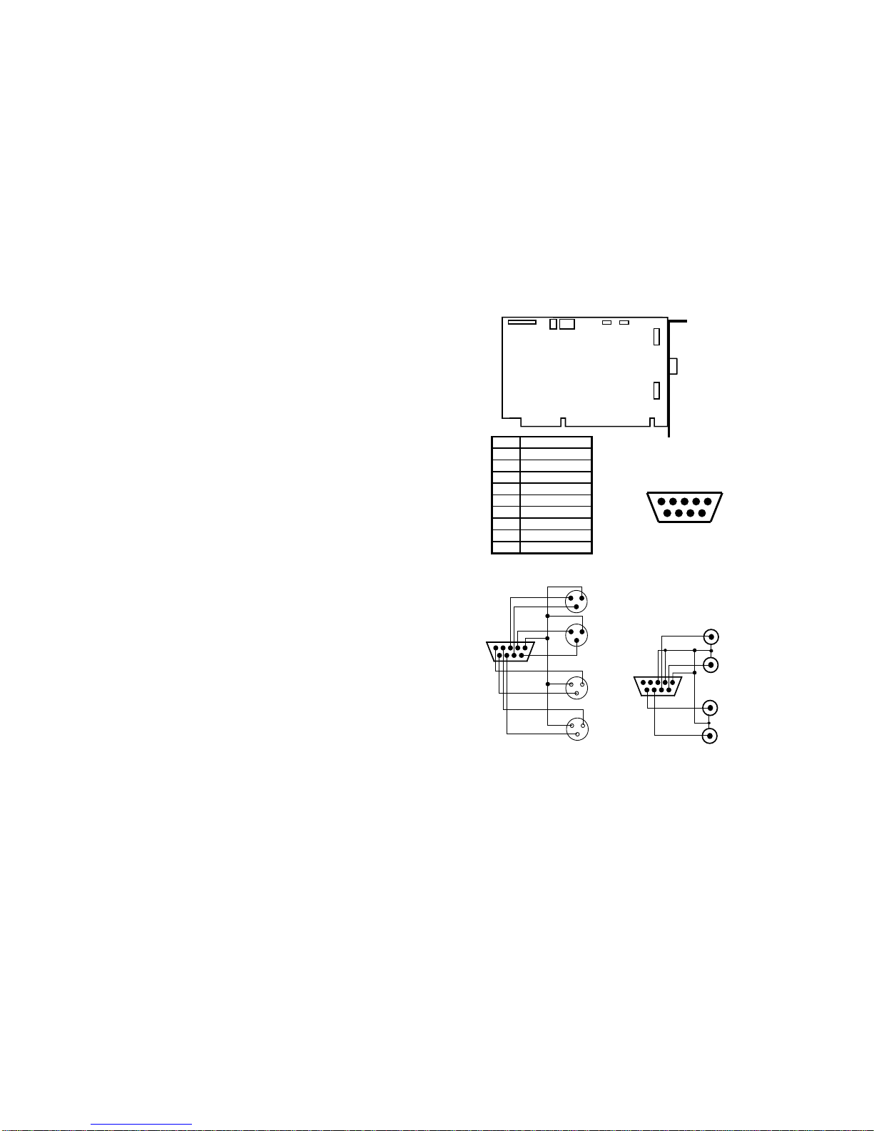
SX-35/36 CONNECTOR DESCRIPTION
JP1
SX-35/36
JP4 JP7
JP8
JP9
BALANCED
IN/OUT
JP3
Pin Assignment
1Ground
2 Right In -
3LeftIn-
4RightOut-
5LeftOut-
6 Right In +
7 Left In +
8RightOut+
9LeftOut+
DB-9
Female
Balanced Analog I /O Connector
12345
6789
SX-35/36 Balanced I/O to XL
R
12345
6789
Balanced In - XLR male shell, female pin
s
Left
Right
1
- 2
+ 3
GND
Right
Balanced Out - XLR female shell, male pins
1
1
1
+ 3
Left
- 2
- 2
+ 3
- 2
+ 3
SX-35/36 Unbalanced I/O to RC
A
12345
6789
Left
Unbalanced Out - Female RCA
Right
Left
Right
Unbalanced In - Female RCA
Figure 2. SX-35/36 Connections
Questo manuale è adatto per i seguenti modelli
3
Indice
Altri manuali Antex electronics Adattatore


