APG LPU-2428 Manuale utente

APG
R
Doc #9004794
Rev A, 04/2016
LPU-2428 & RST-4101
User Manual
www.calcert.com [email protected]1.888.610.7664 0
5
10
15
20
25
30

ii
Table of Contents
Introduction ................................................................................................................ iii
Warranty and Warranty Restrictions.................................................................... iv
Chapter 1: Specications and Options..................................................................... 1
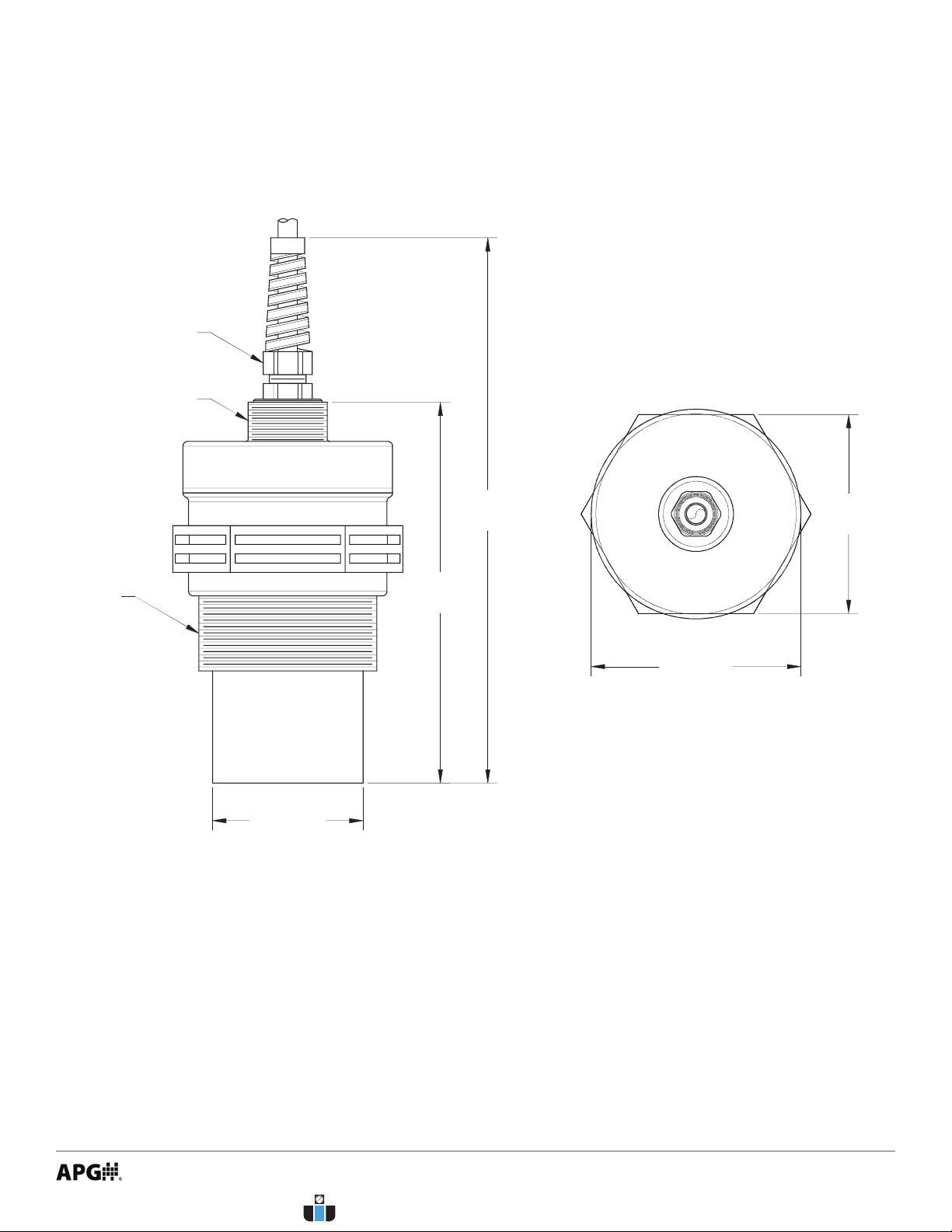
Dimensions ........................................................................................................................................1
Specications ................................................................................................................................... 2
Chapter 2: Installation and Removal Procedures and Notes..............................3
Tools Needed..................................................................................................................................... 3
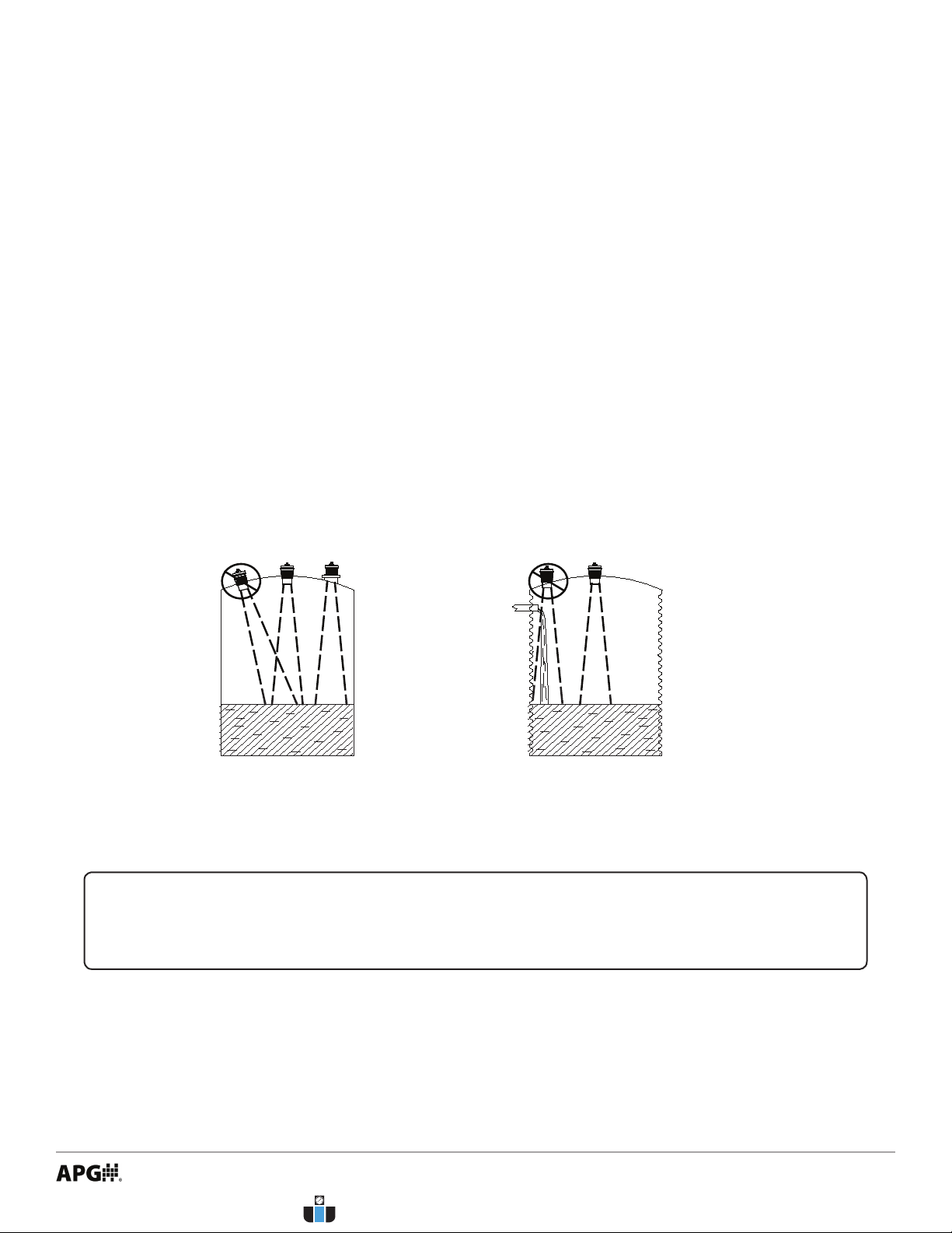
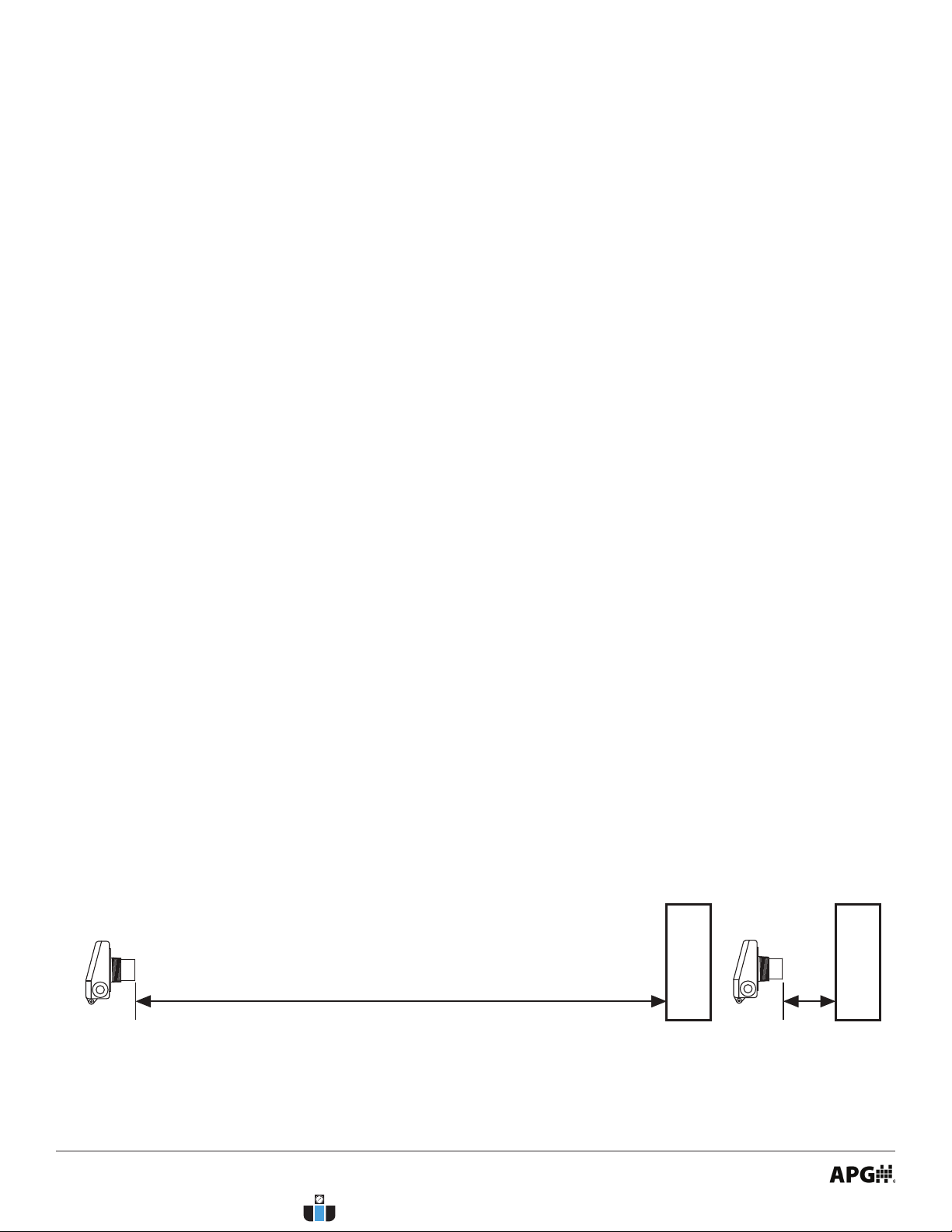
Installation Notes ............................................................................................................................ 3
Mounting Instructions ................................................................................................................... 4
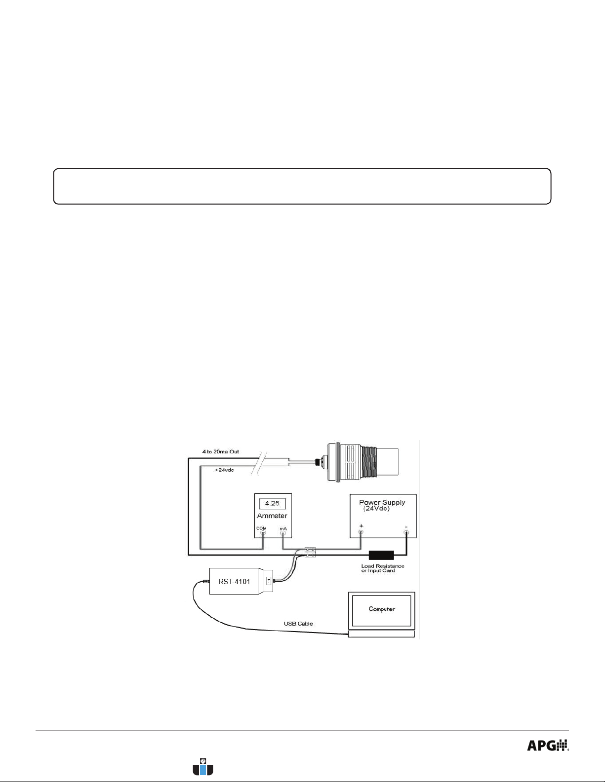
Electrical Installation ..................................................................................................................... 4
Software Installation....................................................................................................................... 5
Removal Instructions ..................................................................................................................... 5
Chapter 3: Maintenance .............................................................................................5
General Care...................................................................................................................................... 5
Troubleshooting............................................................................................................................... 6
Calibration ..................................................................................................................................... 6-7
Repair and Returns.......................................................................................................................... 7
Chapter 4: Programming and Parameter Conguration .....................................8
Software User Interface.............................................................................................................. 8-9
Programming the LPU-2428........................................................................................................ 10
Basic Setup Menu ..................................................................................................................... 11-12
App. Setup Menu.......................................................................................................................13-31
4-20 Setup Menu.......................................................................................................................31-32
Calibration Menu ..................................................................................................................... 33-34
Advanced Menu ....................................................................................................................... 34-36
Utilities Menu........................................................................................................................... 36-38
Totalization Menu..........................................................................................................................39
Chapter 5: Hazardous Location Drawing and Certication ............................. 40
Intrinsically Safe Wiring Diagram .............................................................................................40
Hazardous Location Wiring Diagram ........................................................................................ 41
CSA Certicate of Compliance.............................................................................................. 42-45
www.calcert.com [email protected]1.888.610.7664 0
5
10
15
20
25
30

iii
Introduction
Thank you for purchasing an LPU-2428 ultrasonic sensor and RST-4101 programming module from APG. We
appreciate your business! Please take a few minutes to familiarize yourself with your LPU-2428, RST-4101,
and this manual.
The LPU-2428 loop-powered ultrasonic sensor provides a low-power, non-contact level measurement
solution rated for hazardous locations and suitable for harsh chemical environments.
The default Application setting for the LPU-2428 is Distance, which will work in a wide variety of settings. The
LPU-2428 has several additional Application settings that can be congured to meet your needs.
Reading your label
Every APG instrument comes with a label that includes the instrument’s model number, part number, serial
number, and a wiring pinout table. Please ensure that the part number and pinout table on your label
match your order. The following electrical ratings and approvals are also listed on the label. Please refer to
the Certicate of Compliance at the back of this manual for further details.
IMPORTANT: Your LPU-2428 MUST be installed according to drawing 9002747 as
indicated above to meet Instrinsically Safe approvals. Faulty installation will invalidate all
safety approvals and ratings.
Electrical ratings
Input: 12 to 28 Volts DC; Output: 4-20mA
Class I Division 1; Groups C, D T3
Class I, Zone 0, Group IIB
AEx ia IIB T3 (USA): Ta: -40°C to 60°C; IP65
Ex ia IIB T3 (Canada): Ta: -40°C to 60°C; IP65
Vmax Ui= 28VDC, Imax Ii = 130mA, Pmax Pi= 0.91W, Ci= 0nF, Li = 110μH
Install in accordance with drawing 9002747 (page 42).
Input: 12 to 28 Volts DC; Output: 4-20mA
Class I Division 2; Groups C, D T6
Class I, Zone 2, Group IIB
AEx nA IIB T6: Ta: -40°C to 60°C; IP65
Ex nA IIB T6: Ta: -40°C to +60°C; IP65
Install in accordance with drawing 9002745 (page 43).
www.calcert.com [email protected]1.888.610.7664 0
5
10
15
20
25
30

1
Chapter 1: Specications and Options
• Dimensions
5.06
[128.59 mm]
ø2.79
[70.78mm]
2.65
[67.24mm]
2" NPT
THREADS
ø2.00
[50.80 mm]
7.25
[184.15 mm]
3/4" NPT
THREADS
NON-METALLIC
STRAIN RELIEF
www.calcert.com [email protected]1.888.610.7664 0
5
10
15
20
25
30

2
Performance
Operating Range 1 - 25 ft. (0.3 - 7.6 m) on liquids and hard, at surfaces
1 - 10 ft. (0.3 - 3 m) on bulk solids
Analog Output (Sensor) 4-20 mA
Analog Output (Module) USB
Beam Pattern 9° o axis
Frequency 69 kHz
Response Time 0.6 - 3 seconds (dependent on output range)
Sample Rate 3 seconds @ 4 mA
0.6 seconds @ 20 mA
Accuracy
Accuracy ±0.25% of detected range
Resolution 0.1 inch (2.54 mm)
Environmental
Operating Temperature -40 to 60°C (-40 to 140°F)
Internal Temperature Compensation Yes
Enclosure Protection IP65
NEMA rating (Sensor) 4X
Electrical
Supply Voltage (at sensor) 12-28 VDC
Current Draw 22 mA max
Output Signal 3-30 mA max
Load Resistence 150Ω max @ 12 VDC
600Ω max @ 24 VDC
Cable Connection (Sensor) 2-wire cable included
Cable Connection (Module) 2-terminal Pheonix connector, USB
Masterials of Construction
Transducer Housing PVDF (Kynar®)
Upper Housing (Sensor) PC/PBT
Housing (Module) ABS PA-756
• Specications
www.calcert.com [email protected]1.888.610.7664 0
5
10
15
20
25
30

3
Chapter 2: Installation and Removal Procedures and Notes
Tools are not necessary for installing the LPU itself. If you are using a stand pipe to mount your LPU, you will
probably need tools to install the stand pipe, but not for the LPU.
• Tools Needed
• Installation Notes
• Mount your LPU sensor so that it has a clear, perpendicular sound path to the surface being moni-
tored. Your sensor should be mounted away from tank or vessel walls and inlets. See Figure 2.1.
• The sound path should be free from obstructions and as open as possible for the 9° o axis beam
pattern.
Figure 2.1
NOTE: Do not mount the sensor where the beam will intersect objects such as ll
streams, pipes, ladder rungs, wall seams, or corrugated tank walls.
www.calcert.com [email protected]1.888.610.7664 0
5
10
15
20
25
30

4
• Mounting Instructions
For normal operation, connect the provided cable to your control system:
• Connect the red wire to +24 VDC.
• Connect the black wire to 4-20 mA input. Circuit load resistance + input resistence must be greater
than 150Ω. 249Ω is recommended for optimal signal tranmission.
• Refer to drawing 9002747 (page 42) for Intrinsically Safe installation.
• Refer to drawing 9002745 (page 43) for hazardous location installation.
For programming:
• Connect (+) terminal of RST-4101 to +24 VDC supply of sensor (red wire).
• Connect (-) terminal of RST-4101 to 4-20 mA signal from sensor (black wire).
• Ensure that load resistor is between RST-4101 and control network or PLC, rather than between sensor
and RST-4001. (See Figure 2.2)
• Electrical Installation
Mounting your LPU is easy if you follow a few simple steps:
• Never over-tighten the sensor.
• Always screw in your sensor by hand to avoid cross-threading. Thread failure can be a problem if you
damage threads by over-tightening them or by crossing threads.
IMPORTANT: Do not over tighten! The sensor should be threaded in only hand tight.
Figure 2.2
www.calcert.com [email protected]1.888.610.7664 0
5
10
15
20
25
30

5
• Download the LPU-2428A / RST-4101 software zip le from
• Open the zip le.
• Choose “Install” from the options at the top of the zip le window.
• The installation process will prompt you as needed to complete the installation.
• The software will create and run from a folder in your start menu titled “APG”.
• Software Installation
• Ensure that power to the sensor is o.
• Disconnect the cable from the sensor.
• Remove the sensor and store it in a dry place, at a temperature between -40° F and 180° F.
• If the sensor was installed in a hazardous location, ensure that the cable will not be energized while the
sensor is disconnected.
• Removal Instructions
DANGER: Do not disconnect equipment installed in hazardous locations unless power
has been switched o or area is known to be non-hazardous.
Your LPU-2428 ultrasonic sensor is very low maintenance and will need little care as long as it was installed
correctly. However, in general, you should:
• Avoid applications for which the sensor was not designed, such as extreme temperatures, contact with
incompatible corrosive chemicals and fumes, or other damaging environments.
• Inspect the threads whenever you remove the sensor from duty or change its location.
Chapter 3: Maintenance
• General Care
www.calcert.com [email protected]1.888.610.7664 0
5
10
15
20
25
30

6
measure
measure
This procedure uses targets at known distances to calibrate the sensor’s accuracy. A wall or other large, at
object is recommended for the long range target.
• Point the sensor at a target at a known distance near the maximum range of the sensor, 25’ for a single
solid object (See Figure 3.1).
• Adjust the Multiplier value until the distance reading on the sensor matches the actual measured dis-
tance to the target (See Figure 4.29).
• Point the sensor at a target near the minimum measurement range, 1’ plus any Blanking distance (See
Figure 3.2).
• Adjust the Oset value until the distance reading on the sensor matches the actual measured distance
to the target (See Figure 4.29).
• Repeat previous two steps until no further adjustment is required.
• Calibration
Figure 3.1 Figure 3.2
Should you have problems with your LPU-2428, here are some troubleshooting steps.
• Check the received signal strength (just to left of the three Help buttons in the lower right corner. See
Figure 4.32). If the signal strength is low, alternately increase Pulses and Sensitivity (Figure 4.30) until
the signal strength improves.
• Ensure Temperature Compensation (Figure 4.30) is turned on.
• Set the Gain Control to AutoSense (Figure 4.30).
• Ensure that Blanking (Figure 4.30) is accurately set to account for any unwanted targets between the
sensor and the closest acceptable target.
• Trouble Shooting
www.calcert.com [email protected]1.888.610.7664 0
5
10
15
20
25
30

7
NOTE: The Reset parameter in the Utilities Menu (Figure 4.31) will reset the LPU-2428
to factory default settings.
Should your LPU-2428 ultrasonic sensor require service, please contact the factory via phone, email, or
online chat. We will issue you a Return Material Authorization (RMA) number with instructions.
• Phone: 888-525-7300
• Email: [email protected]
• Online chat at www.apgsensors.com
Please have your LPU-2428’s part number and serial number available. See Warranty and Warranty
Restrictions for more information.
• Repair and Returns
www.calcert.com [email protected]1.888.610.7664 0
5
10
15
20
25
30
Altri manuali per LPU-2428
1
Questo manuale è adatto per i seguenti modelli
1
Indice
Altri manuali APG Accessori

APG
APG MNU IS Series Manuale utente

APG
APG MPX Series Manuale utente

APG
APG MPX-E Manuale utente

APG
APG PT-500 Series Manuale utente

APG
APG LPU-2127 Manuale utente

APG
APG IRU-2 4 Series Manuale utente

APG
APG VBL Series Manuale utente

APG
APG MPX Manuale utente

APG
APG MPI-F Series Manuale utente

APG
APG PWS Series Manuale utente

APG
APG RPM Series Manuale utente

APG
APG FLR Series Manuale utente

APG
APG LPU-2127 Manuale utente

APG
APG MPX Series Manuale utente

APG
APG RPM Series Manuale utente

APG
APG MPI-E Manuale utente

APG
APG MPX Manuale utente

APG
APG MPXI-F Series Manuale utente

APG
APG MPX-T Manuale utente

APG
APG B Series Manuale utente


