Aqua Select 832406 Manuale utente
7939
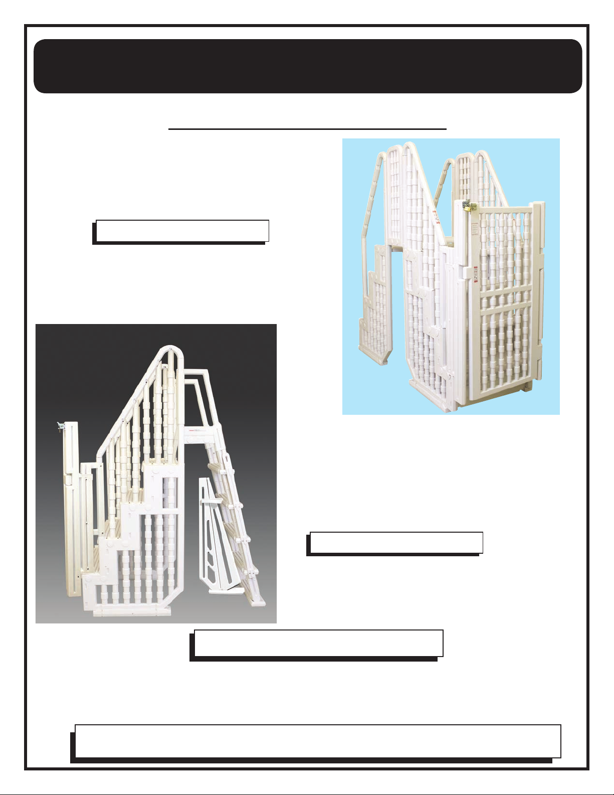
This gate is the final component of the Aqua Select® Everest Bridge System and the Aqua Select® Everest Entry
System. Prior to installing the gate, please follow the instructions included in the other cartons first.
•Phillips head screwdriver
•Drill with 1/16” drill bit
TOOLS REQUIRED
FOR USE WITH:
Aqua Select® Everest
BRIDGE SYSTEM
(832421B)
FOR USE WITH:
Aqua Select® Everest
GATED ENTRY WITH
IN POOL
LADDER
(832406EV)
If you are adding this component after completing the full Aqua Select® Everest step
assembly (832402B), you will need to remove the outside handrails to install the gate.
MODEL
Aqua Select® Gate System
(2) 832402B — Aqua Select® Everest Step
(1) 832405B — Aqua Select ®
Crossover and Enclosure
(1) 832406 — Aqua Select® Gate
CARTONS REQUIRED
(
1) 832402B — Aqua Select® Everest Step
(1) 832405P — Aqua Select® Pickets
(1) 832406 — Aqua Select® Gate
(1) 832406SC — Aqua Select® Heavy Duty In-Pool Ladder
CARTONS REQUIRED
832406
NOTE
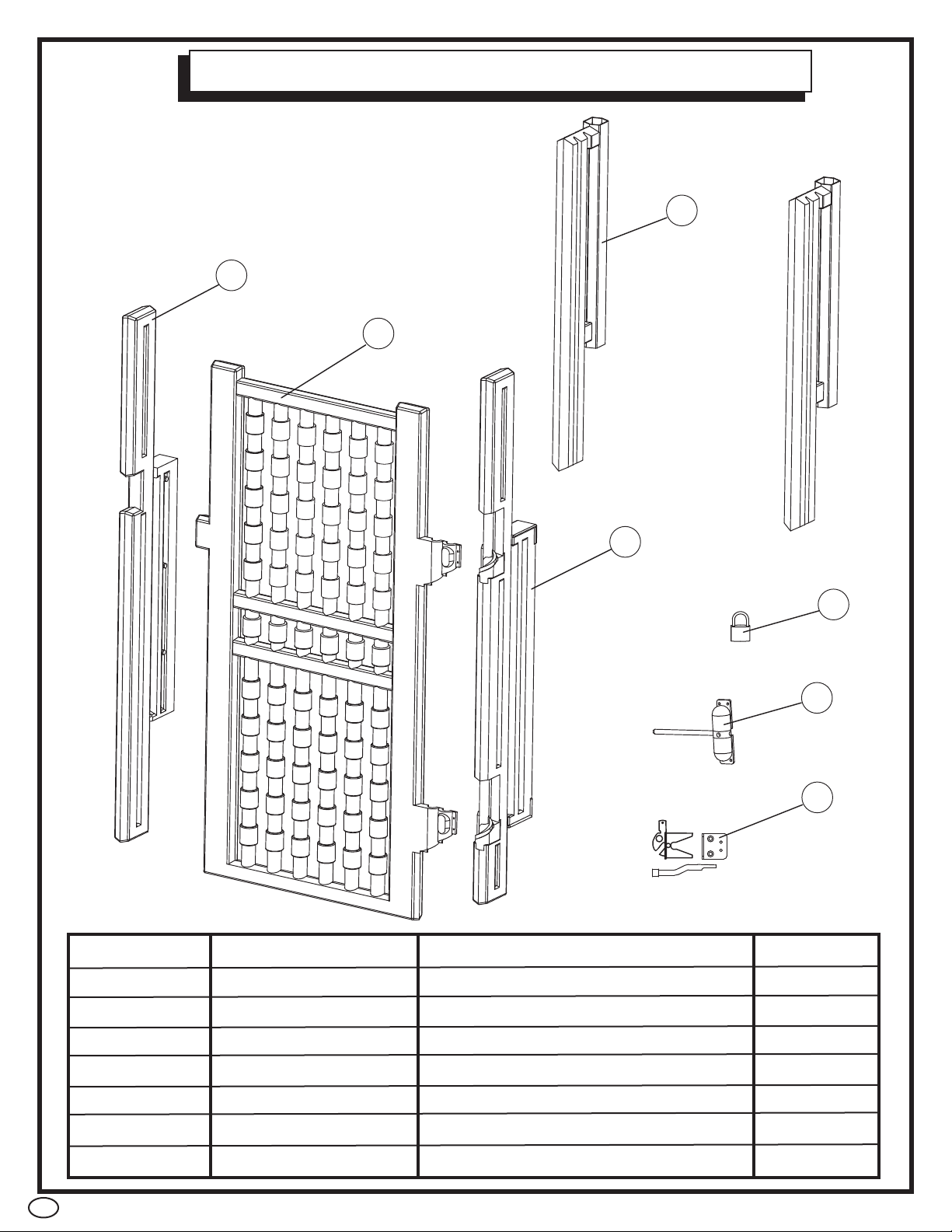
AQUA SELECT®GATE SYSTEM PARTS
2
PART # MODEL # DESCRIPTION QTY
1 AC HINGEPT Hinge Post 1
2 AC GATE Gate 1
3 AC LATCHPT Latch Post 1
4 AC HINGEMT Mounting Post 2
5 AC PADLOCK Padlock 1
6 AC 79073 Optional Gate Closer 1
7 AC GATELATH Gate Latch 1
2
1
4
3
5
6
7
3
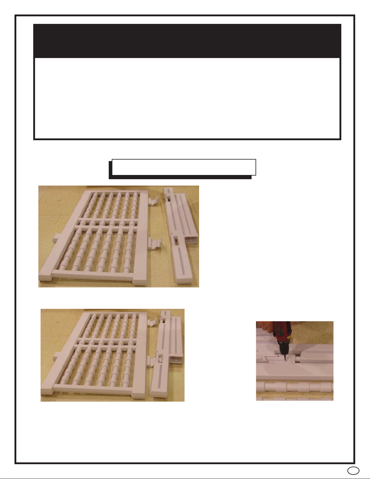
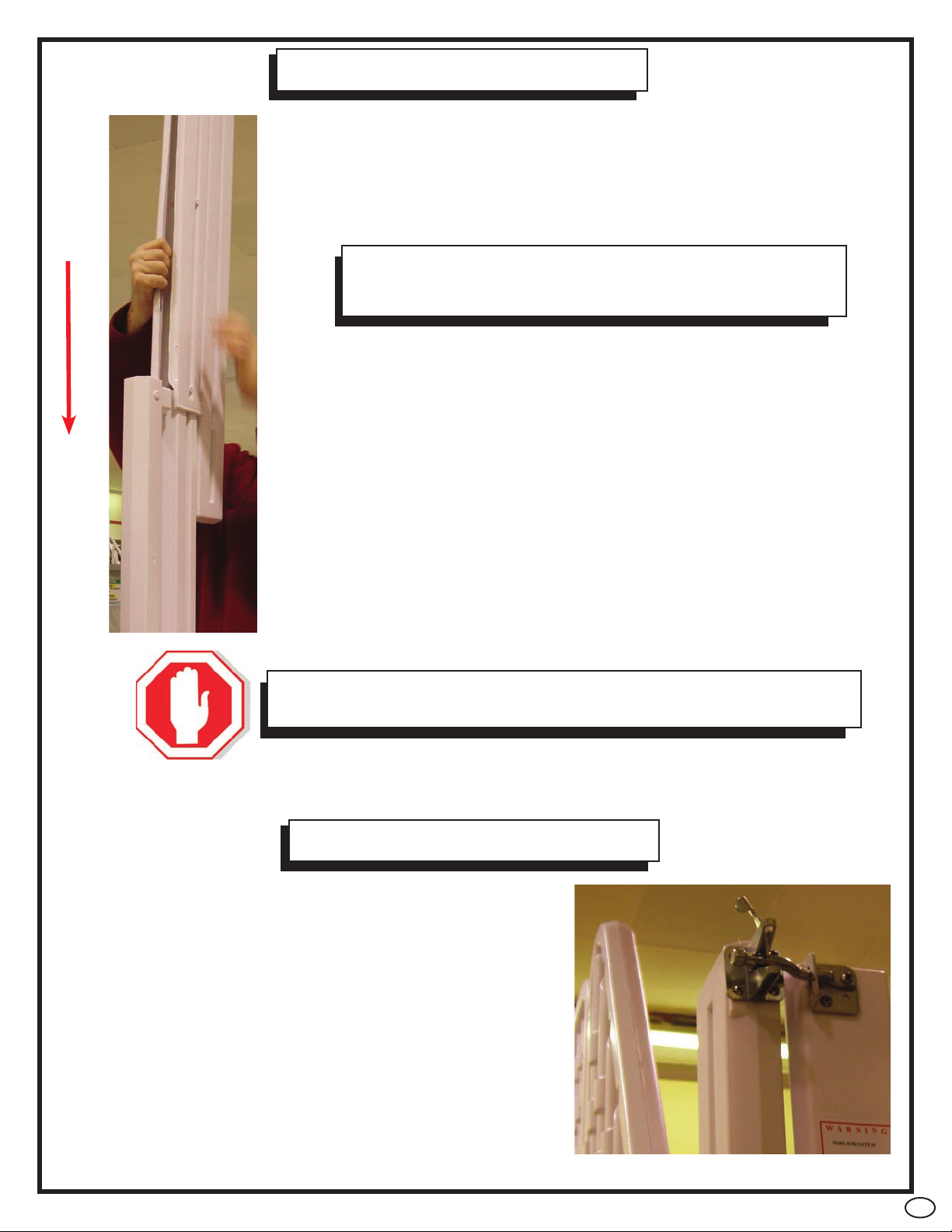
STEP 1
•Lay gate (AC GATE) flat on a clean,
level area and open plastic hinges as
shown.
•
Locate hinge post (AC HINGEPT) and lay next to gate with
openings lined up to plastic hinges of gate.
•Stick plastic hinges of gate through openings of hinge post.
The wider part of the hinge post is the bottom and should be
lined up with the bottom of the gate (flat part indicates
bottom).
•Wrap plastic hinges around hinge
post and secure in place using
(8) of the #7 x 1/2” screws from
hardware (AC HDW30988).
The Ladder must be installed based on Manufacturer’s Instructions
•One person on the Ladder/Stair at a time
•This Ladder is designed and manufactured for a specific Pool Wall Height
and/or Deck of the Pool
•For Entry/Exit of pool, face the ladder at all times
•Remove and secure Ladder when pool is not occupied
•The Ladder will be suitable up to 54” Maximum Pool Height
IMPORTANT SAFETY INSTRUCTIONS
PLEASE READ PRIOR TO ASSEMBLY/USE
4
STEP 2
•The hinge mounting posts (AC HINGEMT) should be
installed onto the
short handrail posts on the second step of the outside stair-
case.
•Attach one hinge mounting post to each of the short handrail
posts with
the long skinny side facing down towards the step.
•Secure in place using (4) of the # 10 x 1-1/4” screws from
hardware (AC HDW30988) through pre-marked openings.
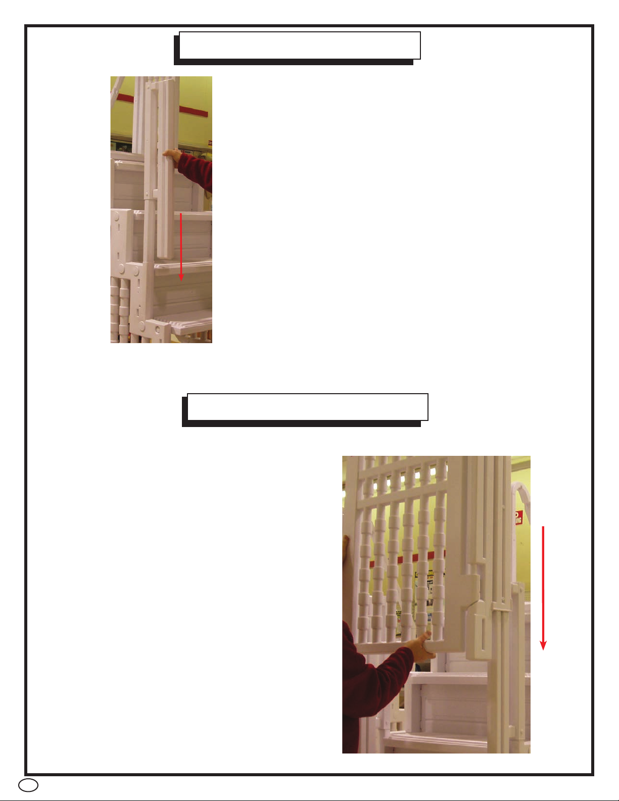
STEP 3
•Slide hinge post with attached gate OVER
hinge mounting post (AC HINGEMT) on
right side of step. Make sure that post is
pushed down completely and that post
touches bottom step of staircase.
Note: It may be necessary to spread the
back of the hinge post open to install.
•Fasten hinge post to mounting post using
(6) of the #10 x 1-1/4” screws
found in hardware bag (AC HDW30988)
through pre-marked openings on inside
and outside of post.
5
STEP 4
NOTE
Picture here shows view from BEHIND step, the
latch mounting post should face the same way
as the hinge post.
•Slide latch mounting post (AC LATCHPT) onto hinge
mounting post (AC HINGEMT) on left side of step.
NOTE: It may be necessary to spread the back of
the latch mounting post open to install.
•The door stop (squared piece sticking out on gate)
should sit perfectly in recessed area of latch mounting
post (AC LATCHPT). If it is NOT sitting correctly, adjust
the height of the latch mounting post until it sits flush.
Once in place, secure post to mounting post using
(6) of the #10 x 1-1/4” screws through pre-marked
openings.
NOTE
Do not install gate latch assembly until the gate is seated
properly otherwise the latch will not catch.
STEP 5
•To complete installation, you will need the gate
latch assembly (AC GATELATH).
•There is a raised area of the latch mounting post
where you will secure the latch itself using
the (4) short screws supplied with the latch.
•Secure bar to either of the far openings on the
plate. Make sure bar lines up with latch so it
will close properly.
•Using two remaining short screws, secure plate to
the corner of the gate through two holes closest to
the latch.
6
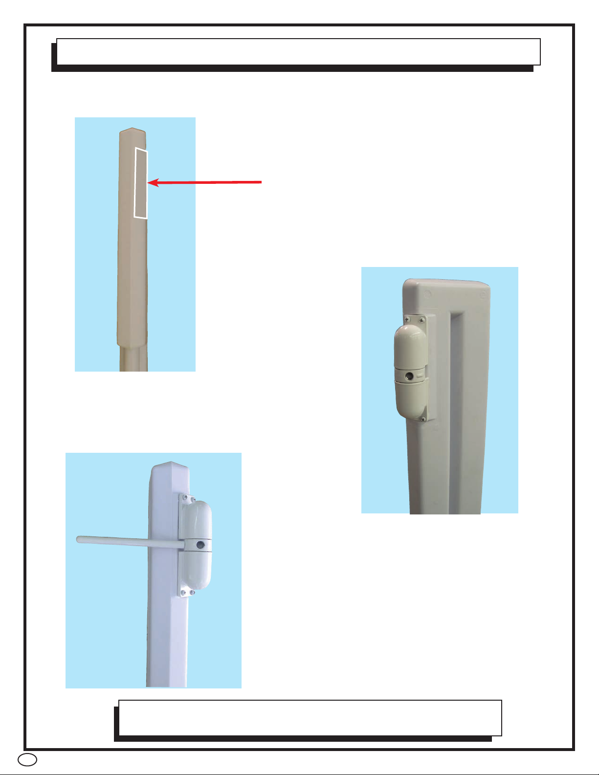
STEP 6 - OPTIONAL GATE CLOSER — AC 79073
•The optional gate closer is designed to assist the gravity close feature of your
Bridge Entry System.
•The arm of the closer must face the latch side
of the gate for the closer to function.
•Secure the closer to the hinge post
with the screws provided with the
closer.
NOTE
Lubrication of the self closer with a silicone based lubricant
will enhance the closers performance.
•The gate closer is to be installed on the hinge
post in the space provided.
•Mount the closer onto the hinged post on the
flat area of the post above the 2 hinges.
7
•When lifting heavy or awkward loads, it is suggested that two people lift to avoid injury.
•DO NOT use the pool entry system for any purpose other than that for which it is intended.
•Maximum weight on steps should NOT exceed 350 lbs.
MAINTENANCE
•Step/ladder/bridges must be removed for winter, failure to do so can cause the step to crack.
•When removing step/ladder/bridges for winter, it is recommended that you spray down step
with hose water to rinse off any chemical residual prior to storing.
•When storing step/ladder/bridges for winter, it should be protected from the elements and
stored either in a shed or garage, or covered with a tarp.
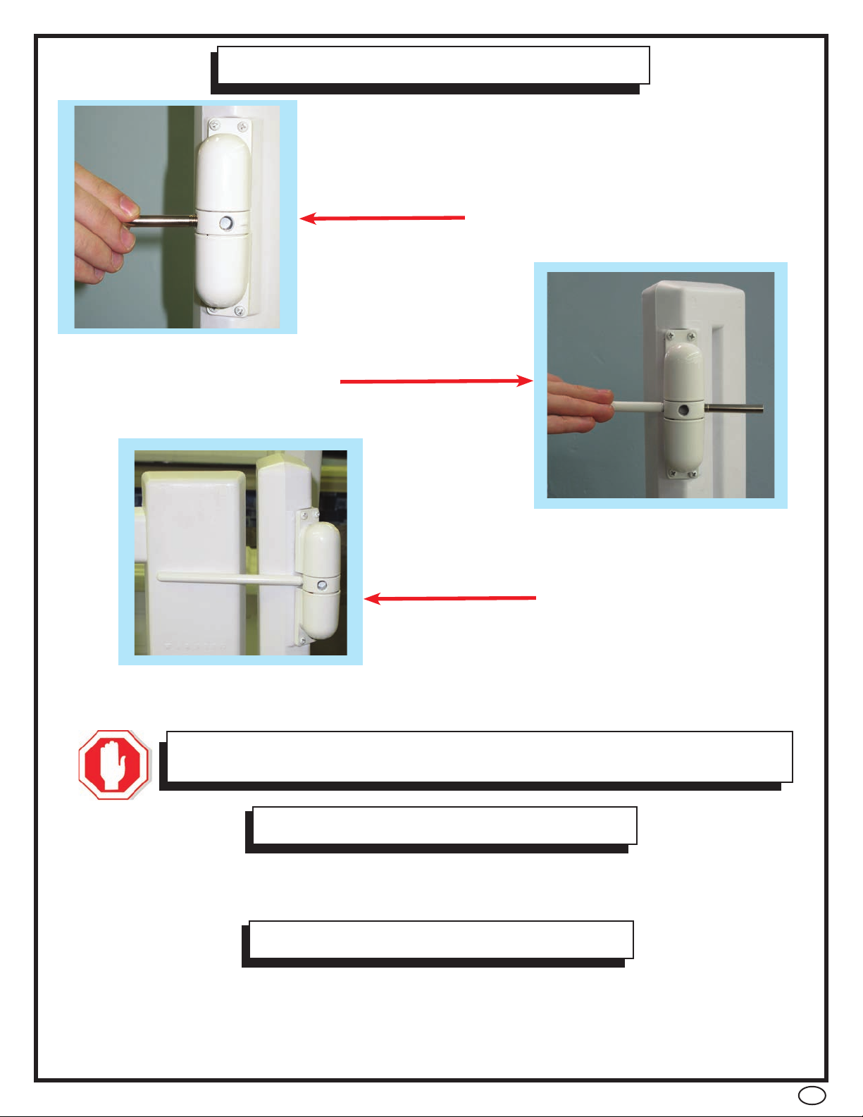
HOW TO SET TENSION
•Turn the center hole away from the
door with the steel bar supplied.
•Remove the steel bar
and allow arm to close.
•To increase or decrease the tension, repeat the above steps one hole at a time
until the desired tension is found.
•Screw the arm into the hole
nearest the gate.
SAFETY INFORMATION
WARNING
Do not over tension the closer. Over tensioning will cause the
spring to buckle and the gate to slam shut and could case damage.

8
STEP MATS
1. Remove step mat from packaging
2. Place step mat onto the bottom of the pool with the smooth side facing down towards the liner
3. Place fully assembled step on top of the step mat. Make sure the step is centered on the step mat
4. Properly secure step to your pool
STEP MATS ARE SOLD SEPARATELY FROM
YOUR POOL STEP
HOW TO INSTALL YOUR STEP MAT
•The use of a step mat is STRONGLY RECOMMENDED with any pool step. Step mats
prevent your pool liner from being damaged by slight movements of your pool step.
USE MODEL 832213
Aqua Select® 36” x 48” STEP MAT
Indice
Altri manuali Aqua Select Scala


