aquatermic XK49 Manuale utente

Owner's Manual
Commercial Air Conditioners
Wired Controller XK49

User Notices
◆The power supply for all indoor units must be unified.
◆Prohibit installing the wired controller at wet or sunshine places.
◆Do not knock, throw or frequently disassemble the wired controller.
◆Do not operate the wired controller with wet hands.
◆In one system network, you must set one indoor unit as the master indoor unit,
Other indoor units are slave indoor units .
◆The operation mode of the system is basing on that of master indoor unit. Master
indoor unit can switch to any modes, while slave unit can’t switch to the mode
that is conflicting with master indoor unit.
◆When master indoor unit changes mode which cause operation mode of
slave indoor unit conflicts with that of system, the operation mode of slave unit
will switch to the operate mode of system automatically.
◆When two wired controllers control one (or more) indoor unit(s), the address of
wired controller should be different.
◆This wired controller should be set as slave controller when it is used to control
one (multiple) indoor unit (s) with other types of wired controller (s).
◆This wired controller is equipped with gate control interface, which can be
connected with gate control system to switch unit on/off by inserting or removing
a card.
◆Functions with “*” are optional for indoor units. If a function is not included in an
indoor unit, wired controller can’t set the function, or setting of this function is
invalid to the indoor unit.

Contents
1. DISPLAY ..............................................................................1
1.1 LCD OF WIRED CONTROLLER.........................................................2
1.2 LCD DISPLAY INSTRUCTION ............................................................3
2. BUTTONS ............................................................................5
2.1 BUTTON GRAPHICS...........................................................................5
2.2 FUNCTION INSTRUCTION OF BUTTONS.........................................6
3. INSTALLATION AND COMMISSIONING.............................6
3.1 INSTALLATION OF WIRED CONTROLLER.......................................7
3.2 COMMISSIONING.............................................................................19
4. OPERATION INSTRUCTIONS...........................................28
4.1 ON/OFF..............................................................................................28
4.2 MODE SETTING................................................................................29
4.3 TEMPERATURE SETTING................................................................29
4.4 FAN SETTING....................................................................................31
4.5 SWING SETTING ..............................................................................31
4.6 REMOTE SHIELD FUNCTION..........................................................31
4.7 CHILD LOCK FUNCTION..................................................................32
4.8 GATE-CONTROL FUNCTION...........................................................32
5. ERROR DISPLAY...............................................................33
5.1 TABLE OF ERROR CODES FOR OUTDOOR UNIT ........................34
5.2 TABLE OF ERROR CODES FOR INDOOR UNIT ............................36
5.3 TABLE OF STATUS CODES .............................................................37
5.4 TABLE OF DEBUGGING CODES.....................................................40

Wired Controller XK49
1
1. DISPLAY
Fig. 1.1 Appearance of wired controller

Wired Controller XK49
2
1.1 LCD of Wired Controller
Fig. 1.2 LCD graphics of wired controller

Wired Controller XK49
3
1.2 LCD Display Instruction
Table 1.1 LCD display instruction
No.
Symbols
Instructions
1
*
Auto mode (Under Auto mode, the indoor units will automatically select their
operating mode as per the temperature change so as to make the ambient
comfortable.)
2
Current set fan speed (including auto, low speed, medium-low speed, medium
speed, medium-high speed, high speed and turbo seven status)
3
Cooling mode
4
Dry mode
5
Fan mode
6
Heating mode
7
When inquiring or setting project number of indoor unit, it displays "NO." icon
8
Display "SET" icon under parameter setting interface
9
Up and down swing function
10
Display "CHECK" icon under parameter view interface
11
Gate-control function
12
Child Lock status

Wired Controller XK49
4
13
Outdoor unit defrosting status
14
Shielding status
15
It shows the setting temperature value(In case the wired controller is
controlling a Fresh Air Indoor Unit, then the temperature zone will display
FAP)
16
One wired controller controls multiple indoor units
17
Memory status (The indoor unit resumes the original setting state after power
failure and then power recovery)
18
Current wired controller connects master indoor unit
19
The data display area will help to show the parameters checked or set
20
It indicates the current wired controller is the slave wired controller
(address of wired controller is 02)

Wired Controller XK49
5
2. BUTTONS
2.1 Button Graphics
Fig. 2.1 Button graphics

Wired Controller XK49
6
2.2 Function Instruction of Buttons
Table 2.1 Function instruction of buttons
No.
Buttons
Instructions
1
SWING
It’s used to set swing status.
2
FAN
Switch among auto, low speed, low-medium speed, medium speed,
medium-high speed, high speed and turbo status
3
ON/OFF
Indoor unit On/Off
4
(1) Set operating temperature of indoor unit
(2) Set and inquiry parameter
5
6
MODE
Switch Auto, Cooling, Dry, Fan, Heating modes for indoor unit. (Note: The Floor
Heating, 3D Heating and Space Heating function icon will show up when the
unit has those functions.)
4+5
+
Simultaneously press “ ” and “ ” for 5s to enter or cancel the Child Lock
function.
3. INSTALLATION AND COMMISSIONING
Fig. 3.1 Dimension of wired controller
Wired Controller XK49
7
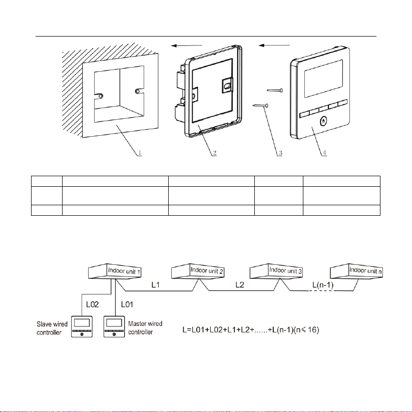
Fig. 3.2 Parts of wired controller
No.
1
2
3
4
Name
Junction box embedded in
the wall
Soleplate of wired
controller
Screw
M4*25
Panel of wired
controller
Q'ty
User-supplied
1
2
1
3.1 Installation of Wired Controller
3.1.1 Communication Line Selection
Fig. 3.3 Length of communication line
Indice
Lingue:
Altri manuali aquatermic Controllori


