aquilar AquiTron AT-APA Manuale utente

AT-APA
Addressable Pinpoint Alarm
AquiTron
INSTALLATION
INSTRUCTIONS

APA
230/120Vac, 50/60Hz , 12Vdc, 7 watts
POWER CONSUMPTION
10 watt maximum
RELAYS
Number: 2 independent potential-free relay
contacts. The rst relay switches o if there
is a power failure or system fault. The second
relay switches off if a water leak is detected.
Type: SPDT
Rating: 3 A at 250Vac/24 Vdc
TOUCHSCREEN
7 inch. Resolution: 800 x 480 pixels. Screen
size 155 x 86 mm.
ENCLOSURE
Powder Coated Metal 200 mm x 240 mm x
55 mm (L x H x D)
TYPES OF LEAK DETECTION CABLE
Works with all TraceTek leak detection cables
(see technical datasheets)(TT1000, TT1100,
TT3000, TT5000, TT5001, TT7000)
Please read these
instructions carefully
and keep them in a
safe place (preferably
close to the module)
for future reference.
These instructions
must be followed
carefully to ensure
proper operation.
AT-APA
Addressable Pinpoint Alarm
A. GENERAL INFORMATION
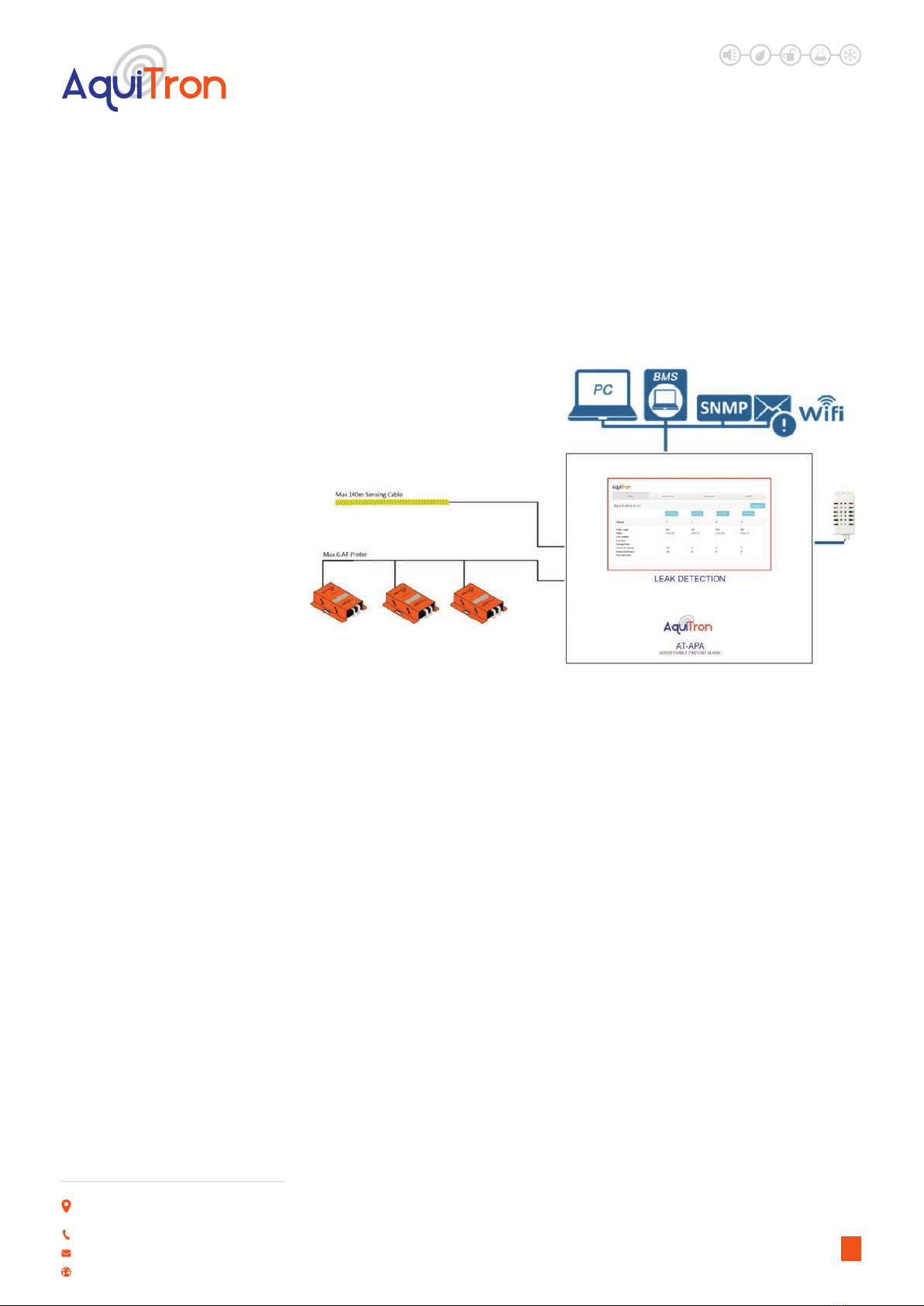
This compact module is suitable for integration into the building’s computer network, and
in the event of a leak it will automatically send an alert to notify engineers of the problem.
The module can be easily congured and data consulted either locally via the touchscreen or
remotely via the built-in web server. Any alarms are shown on the module’s touchscreen, and a
buzzer activated. Automatic alarms are sent via SNMP or email, and the alarm relay is enabled.
All alarm data can be viewed remotely. All alarms are stored in the module’s memory, together
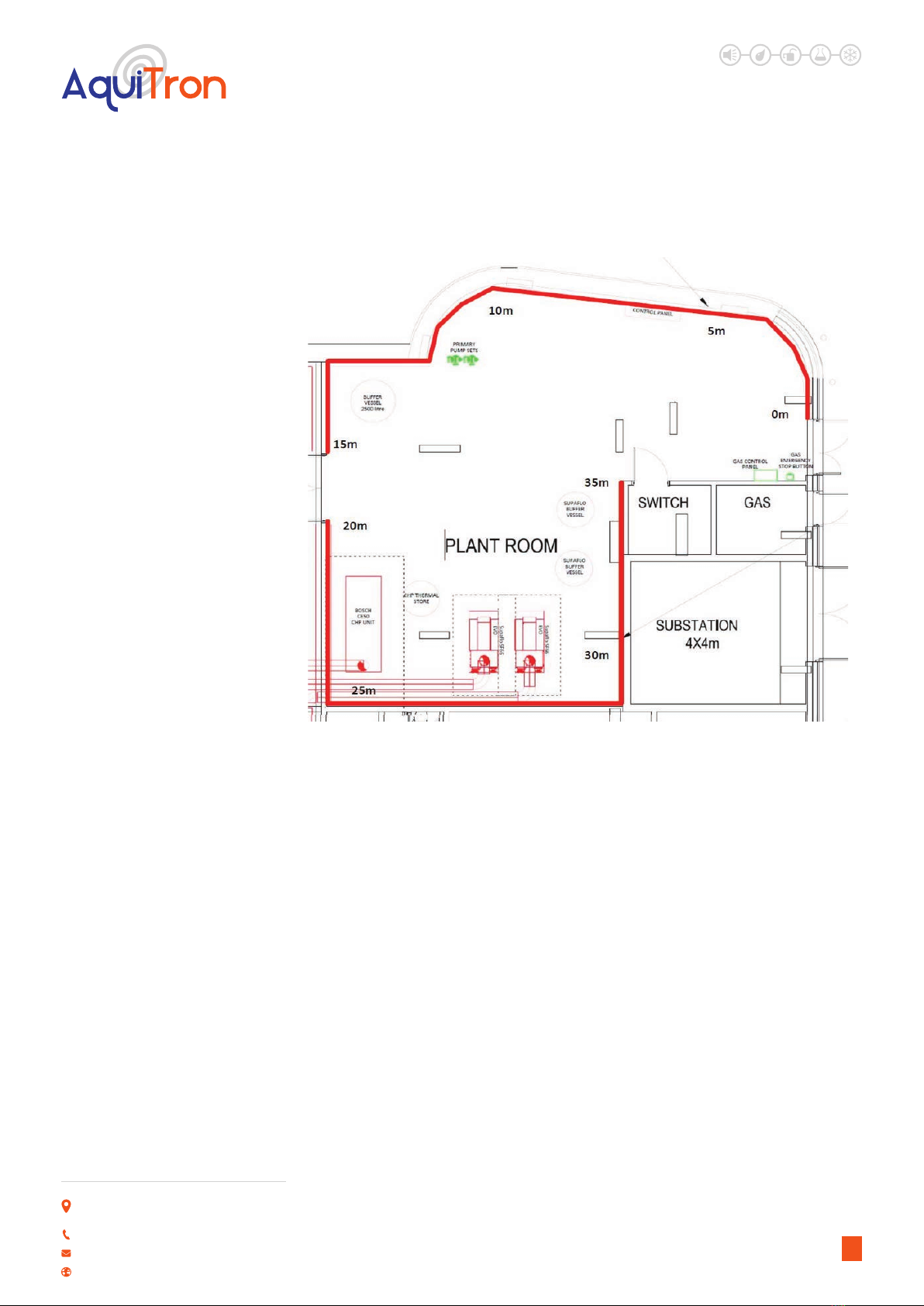
with the timestamp and details. The location of the leak is easy to identify on a diagram in PDF
format, which can be loaded into the alarm module. Up to 4 hardwired leak detection circuits
can be connected to the module. 6 leak detection probes or up to 100 metres of leak detection
cable can be connected to each circuit. The AT-APA can be easily integrated into any building
management system by connection to the volt free relay contacts or reading the standard
Modbus TCP/IP registry.
B. PRODUCT INFORMATION
LEAK DETECTION SOLUTIONS
1
TYPES OF DETECTION PROBES
Works with AT-PROBE-TS/M water leak
detection probes (see technical datasheets)
MAXIMUM CIRCUIT LENGTH
100 metres Tracetek Cable (328 ft) per zone
or 6 x AT-PROBE-M/TS
OPTIONAL AMBIENT SENSOR
Combined temperature and humidity
sensor which can be directly connected and
congured.
NUMBER OF CIRCUITS
Choice of 1, 2, 3 or 4 circuits up to 100 metres
sensing cable or 6 probes on each.
CONNECTION TO NETWORK
LAN via RJ45 connector.
CONNECTION TO MODULE
Via the built-in WiFi, or via a LAN connection.
LOADING OF DIAGRAM
Diagram in PDF format
APPROVALS
LVD: 60950:2001 +A11:2004
EMC: Emission: EN61000-6-3
Immunity: EN61000-6-1 :2001
Unit 30, Lawson Hunt Industrial Park,
Broadbridge Heath, Horsham, West Sussex,
RH12 3JR
+44 (0) 1403 216100
www.aquilar.co.uk
AT-APA
Addressable Pinpoint
Alarm
LEAK DETECTION SOLUTIONS
•Alarm module for water leak detection with touchscreen, built-in web server and link
to the BMS via the Modbus register.
•All data and alarms can be continuously consulted via the LAN.
•Accurate indication of the location of the leak.
•Automatic alarm alert via relay, SNMP trap and alarm email.
2
ALARM NOTIFICATIONS
Onscreen display
Audible alarm
Alarm emails are sent automatically.
Via SNMP trap or Modbus register.
Via connection to the built-in alarm relay
COMMUNICATION WITH THE BMS OR
SNMP MANAGEMENT SYSTEM
Modbus TCP/IP register SNMP trap
Unit 30, Lawson Hunt Industrial Park,
Broadbridge Heath, Horsham, West Sussex,
RH12 3JR
+44 (0) 1403 216100
www.aquilar.co.uk

AT-APA
Addressable Pinpoint
Alarm
LEAK DETECTION SOLUTIONS
3
CONTENTS
1.0 Installing and Connecting the alarm module Page 4
2.0 Detailedcongurationofthemoduleusingthe Page5
integrated web server
3.0 Alarm on a leak detection cable Page 7
4.0 Alarm history Page 7
5.0 Conguration Page8
6.0 Congurationofcircuit1,2,3or4 Page10
7.0 Congurationofoptionalambientsensor Page11
8.0 ModbusTCP/IPregisters Page11
9.0 Setting the IP address in a laptop or desktop Page 12
(WindowsManagementSystem)
10.0 Guarantee Page 14
Unit 30, Lawson Hunt Industrial Park,
Broadbridge Heath, Horsham, West Sussex,
RH12 3JR
+44 (0) 1403 216100
www.aquilar.co.uk
LEAK DETECTION SOLUTIONS
4
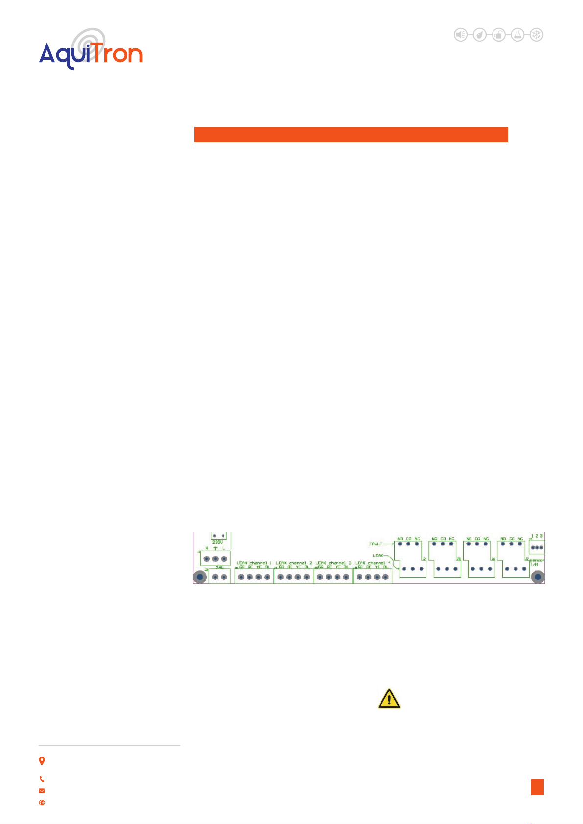
1. INSTALLING AND CONNECTING THE ALARM MODULE:
Mountthehousingagainstthewall.Usetheholesprovidedontheoutsideofthe
housing. Connect the cables to the module as shown in the diagram below. Holes are
providedforthispurposeinthebottomofthehousing,togetherwithcableglands.
A. CONNECTING THE POWER SUPPLY:
Depending on power supply available connect
the cable that powers the module to the 24
VAC, 12/24 VDC terminals or the 230Vac
terminals.
B. ISOLATE SPARE SENSING ZONES
CONNECTING THE LEAK DETECTION
CIRCUITS:
Connect 4 two-wire water leak detection circuit
cables (leak detection cable sensor or probe)
to the GR-RE-YE-BL terminals of LEAK circuit 1,
2, 3 or 4.
ATTENTION: Note the colour of the cables to
the terminals. G = Green, R = Red, Y = Yellow
and B = Black. Up to four separate circuits may
be connected to the panel. If any circuits are
left unused. These circuits must either be
disabled in the software, or bridging wires
must be used to connect the Y terminal to the
B terminal and the G terminal to the R
terminals.
C. OPTIONAL: CONNECTING THE
AMBIENT SENSOR:
Connect the optional AT-APA-HTS sensor to
the connector marked “sensor T/H” on the
bottom right:
CONNECTING TO THE COMPUTER
NETWORK:
The network cable is connected to the
module via an M20 RJ45 connector mounted
on the bottom of the panel case.. Correct
Ethernet connection is indicated by the lights
being on. This module contains an integrated
web server. When correctly connected, the
module can be accessed by all the computers
on the network
Note: The AquiTron Addressable Pinpoint
Alarm module is now ready for use.
Additional settings for sending alarms or
uploading a diagram must be done via the
touchscreen, or via a computer or tablet with
a standard web browser.
Note: To prevent any risk of damage to
the user or module, the power supply
should only be switched on after all the
cables are connected and the housing closed.
AT-APA
Addressable Pinpoint
Alarm
•Connect the black wire to terminal 1
•Connect the yellow wire to terminal 2
•Connect the red wire to terminal 3
The AT-APA-HTS comes with a 5m cable
attached. This can be cut down to required
length. But distance should not be increased.
D. NOTIFICATION VIA RELAY
CONTACTS:
All data from the module is transmitted to the
BMS via the network, or the external alarm
system via the Modbus TCP/IP register.
However, if you require relay contacts for
sending to an external system, then connect
a cable to the appropriate relays below the
module. The upper row of relay outputs
(FAULT) switch each circuit in the event of
a cable or system fault. These relays switch
on if the module is connected to the power
supply, and switch o if there is a power
failure or system fault. The lower row of relay
outputs (LEAK) switch each circuit in the event
of an alarm.
Unit 30, Lawson Hunt Industrial Park,
Broadbridge Heath, Horsham, West Sussex,
RH12 3JR
+44 (0) 1403 216100
www.aquilar.co.uk

LEAK DETECTION SOLUTIONS
5
1.0 VIA TOUCHSCREEN
The AT-APA features a built-in touchscreen
where detailed settings can be changed
easily. If elds where data has to be entered
are selected, an onscreen keyboard appears.
The home page displays the system status and the status of the active leak detection circuits.
•Cable length: this is the total length of leak detection cable connected to a circuit.
•Status: this is the status of the leak detection cable (see below).
•Leak location: this is the location where the leak alarm is active.
•Leak zone: this is the zone where the leak alarm is active.
•Leak value: this is a value expressed in %, where 100% represents a leak.
•YB resistance loop: this is the measured resistance value in ohms of the Yellow-Black
detection circuit.
•RG resistance loop: this is the measured resistance value in ohms of the Red-Green detection
circuit.
•Alarm timestamp: this is the time when an alarm was activated.
2. DETAILED CONFIGURATION OF THE MODULE USING THE
INTEGRATED WEB SERVER:
ThedetailedsettingsoftheAT-APAcanbechangedwiththetouchscreenorbytheweb
application that can be accessed via a standard web browser. There are two ways to
connecttothewebapplication;viaahardwirednetworkcableconnection,ortheAT-
APA’sWi-Ficonnection.
2.0 VIA WIFI NETWORK
The AT-APA has its own “Aquitron_AT-APA”
WiFi network. Connect to the WiFi network
via tablet, laptop or computer. After the WiFi
connection is established, open the web
browser and enter the following address in
the command bar: http://10.0.0.1. The home
screen should now be shown on your device.
3.0 VIA HARDWIRED CONNECTION
WITH A NETWORK CABLE
Connect a network cable between the AT-APA
and the computer or laptop that will carry out
the conguration. By default, the IP address
of the AT-APA is set to 10.100.100.106. The
computer or laptop must be in the same IP
range to establish a connection (to make any
modications, see section 9 “Setting the IP
address in a laptop or desktop” at the end
of this document). After these modications
have been made, open the web browser and
enter the following address in the command
bar: http://10.100.100.106. The home screen
below will appear on your computer.
AT-APA
Addressable Pinpoint
Alarm
Unit 30, Lawson Hunt Industrial Park,
Broadbridge Heath, Horsham, West Sussex,
RH12 3JR
+44 (0) 1403 216100
www.aquilar.co.uk
LEAK DETECTION SOLUTIONS
6
•A PDF diagram of the leak detection area can be loaded into the LDM for each circuit. Click the
“Show Diagram” button to view each circuit.
AT-APA
Addressable Pinpoint
Alarm
Unit 30, Lawson Hunt Industrial Park,
Broadbridge Heath, Horsham, West Sussex,
RH12 3JR
+44 (0) 1403 216100
www.aquilar.co.uk

LEAK DETECTION SOLUTIONS
7
3 ALARM ON A DETECTION CABLE
Ifanalarmisactivatedbyaleakdetectioncableorprobe,itisdisplayedonthehome
pageasfollows:
ALARM BUZZER
The alarm buzzer is activated with each new alarm, and can be stopped by pressing “Stop
Buzzer” on the touchscreen. This buzzer can also be stopped remotely via the web application
using a computer or tablet with access to the network.
4 ALARM HISTORY
AllalarmsactivatedintheAT-APAarestoredinthememory,togetherwithatimestamp.
Theseeventscanbeconsultedatanytime,andcanalsobedownloadedtoaCSVle.The
last15alarmsarealwaysdisplayed.Selectthedaterangetoretrieveanddownloadolder
events.
AT-APA
Addressable Pinpoint
Alarm
Unit 30, Lawson Hunt Industrial Park,
Broadbridge Heath, Horsham, West Sussex,
RH12 3JR
+44 (0) 1403 216100
www.aquilar.co.uk

LEAK DETECTION SOLUTIONS
8
AT-APA
Addressable Pinpoint
Alarm
5 CONFIGURATION
TheAT-APAcanbecompletelysetuponthecongurationpageviathetouchscreen,
computerortablet.Toenterthecongurationpageapasswordmustbeentered.
Note: To log in to the conguration area, enter a password. The default password is “admin”.
Select the box. A keyboard appears on the touchscreen. Enter this password, and the home
page appears. You will now be able to enter the conguration page.
Unit 30, Lawson Hunt Industrial Park,
Broadbridge Heath, Horsham, West Sussex,
RH12 3JR
+44 (0) 1403 216100
www.aquilar.co.uk

LEAK DETECTION SOLUTIONS
9
AT-APA
Addressable Pinpoint
Alarm
OPTIONS AVAILABLE ON THIS PAGE ARE:
General: enter a name and location for the panel, and select the language if required.
Leak detection settings: click on circuit 1, 2, 3, 4 and/or Ambient to adjust the settings of the
leak detection cables and ambient sensor.
Password: the login password can be modied here. First enter the old password, then the
new password and click ‘Save’. If you do not tick Enable Password Protection, no password is
required to access the data. A password is always required for configuration.
Warning: Please keep the new password in a safe location. If the password is changed
then lost you will not be able to access the configuration area of your panel without
returning it to Aquilar for a factory reset. This will result in all settings, including history, being
lost.
Factory reset due to a lost password is not considered a warranty issue and is chargeable.
NetworkConfiguration:select whether to use a fixed IP address or a DHCP address. Enter the
settings if a fixed IP address is used.
SNMP:enter the settings for the SNMP trap receiver if an SNMP trap must be sent in the event
of an alarm. The MIB table can also be downloaded with the ‘Download MIB Table’ button. Note:
The ‘Sent SNMP Trap’ option must still be selected on the relevant circuit configuration page
under alarm action definition for SNMP traps to actually be sent.
EmailConfiguration:enter the settings for the mail server and the recipients if an alarm email
must be sent in the event of an alarm. Click ‘Save’ to save the settings. Note: The ‘Sent Mail’
option must still be selected on the relevant circuit configuration page under alarm action
definition for email notifications to actually be sent.
Leak detection settings: click circuit 1, 2, 3, 4 and/or Ambient to configure the settings of the
leak detection cables.
Unit 30, Lawson Hunt Industrial Park,
Broadbridge Heath, Horsham, West Sussex,
RH12 3JR
+44 (0) 1403 216100
www.aquilar.co.uk
Indice
Altri manuali aquilar Sistema di sicurezza

aquilar
aquilar AquiTron AT-RAP-230 Istruzioni per l'installazione

aquilar
aquilar SD2 Guida all'installazione

aquilar
aquilar AquiTron AT-RAP-230 Istruzioni per l'installazione

aquilar
aquilar DOLEJSZ AquiTron AT-RAP-12 Istruzioni per l'installazione

aquilar
aquilar AquiTron AT-ZAP Guida

aquilar
aquilar AquiTron AT-MZA Manuale utente
Manuali Sistema di sicurezza popolari di altre marche


EDM
EDM Solution 6+6 Wireless-AE Manuale utente

Highway Safety Group
Highway Safety Group EA401 Manuale utente

Siren
Siren LED GSM Manuale utente

Detection Systems
Detection Systems 7090i Istruzioni per il montaggio

Se-Kure Controls
Se-Kure Controls MicroMini SK-4841 Manuale utente

Siemens
Siemens FDM273 Manuale utente