ARC MWMR-250 Manuale utente
1
Issue Date: 5/2/2020
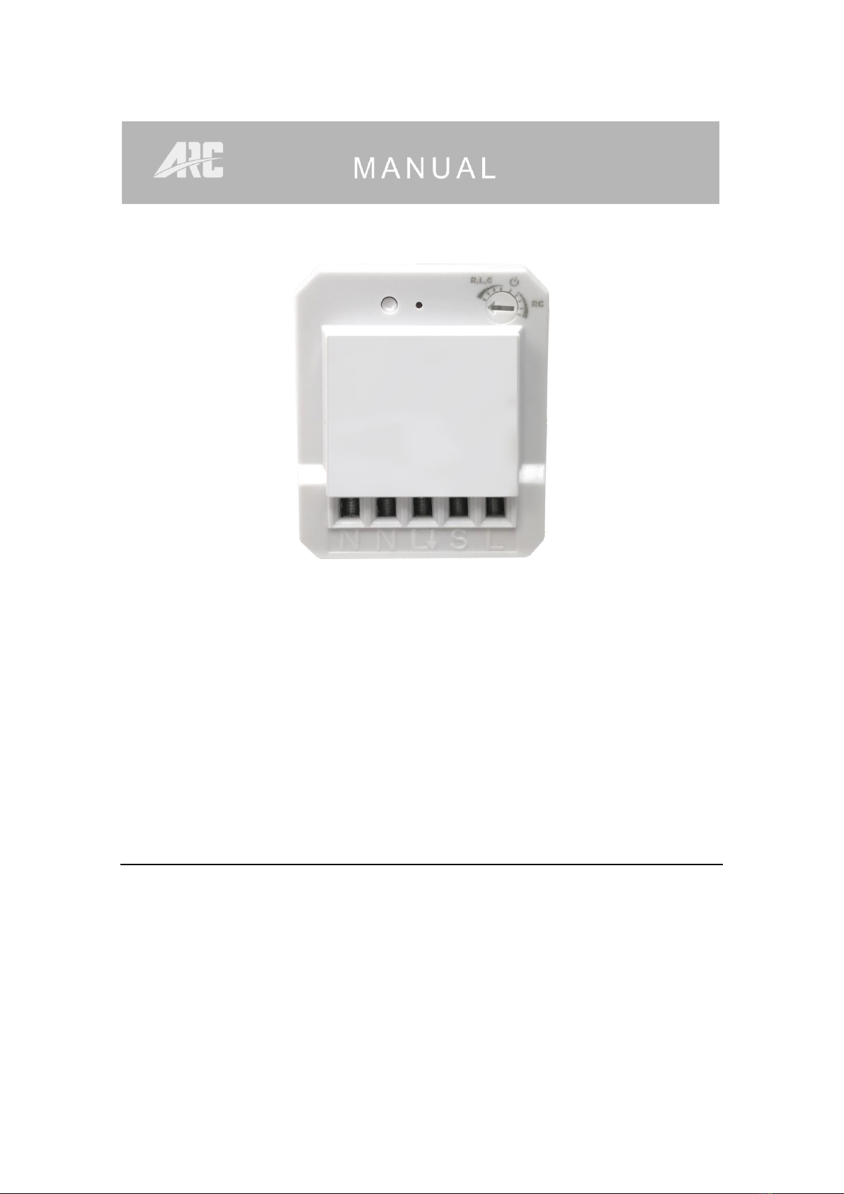
WIRELESS DIMMER
MINI WALL MODULE
MWMR-250
CONTENTS
1. Overview and features Page 2.
2. Diagrams Page 3.
3. Installation –Wiring Page 4.
4. Pairing / Un-pairing device Page 7.
5. Non-Dimmable / Trailing & Leading Edge setup Page 9.
6. Operation Page 11.
7. Specifications Page 13.

2
Issue Date: 5/2/2020
1.Overview and features
Remotely controlled 250W universal Mini Dimmer Wall Module is designed to
control existing dimmable LED, dimmable energy saving lamp, incandescent
lamp, 230V~ halogen lamp and 12V halogen lamp with inductive transformer or
electronic transformer.
Especially designed for Rocker Switch control.
Main features of Mini Wall Module;
•Compatible to L and M series.
•Operating mode of Trailing Edge or Leading Edge.
•Ability to work with existing rocker switch for On / Off / Dimmer function.
•Minimum brightness setup for different kinds of dimmer loads.
•Small compact size for installation into wall box or inside light fittings
•32 memories, first in first out storage maintain.
•Memory of last brightness level.
•Scene status memory, create your desired atmosphere.
•2-way switch function.
Supported Load;
•230V operated conventional incandescent and halogen light source
•12V electronic transformers
•12V inductive transformers
•Dimmable and non-dimmable energy saving lamp
•Dimmable and non-dimmable LED
Not compatible to:
Fluorescent lamp
Momentary / push button switch
ARC Code switch system product range
OVERVIEW AND FEATURES
OVERVIEW AND FEATURES

3
Issue Date: 5/2/2020
2.Diagrams
Notes for the diagrams:
N - Terminal for neutral wire
L- Output terminal for load wire
S - Terminal for power supply to the switch
L - Terminal for live wire
⚫Strip the solid wires (rigid conductor only) at least 7mm then connect the
wires as per diagrams below, ensure terminals are properly tightened and
no bare wire is visible.
⚫Suitable wire size for terminal is 1.6mm2 to 2mm2
DIAGRAMS
4
Issue Date: 5/2/2020
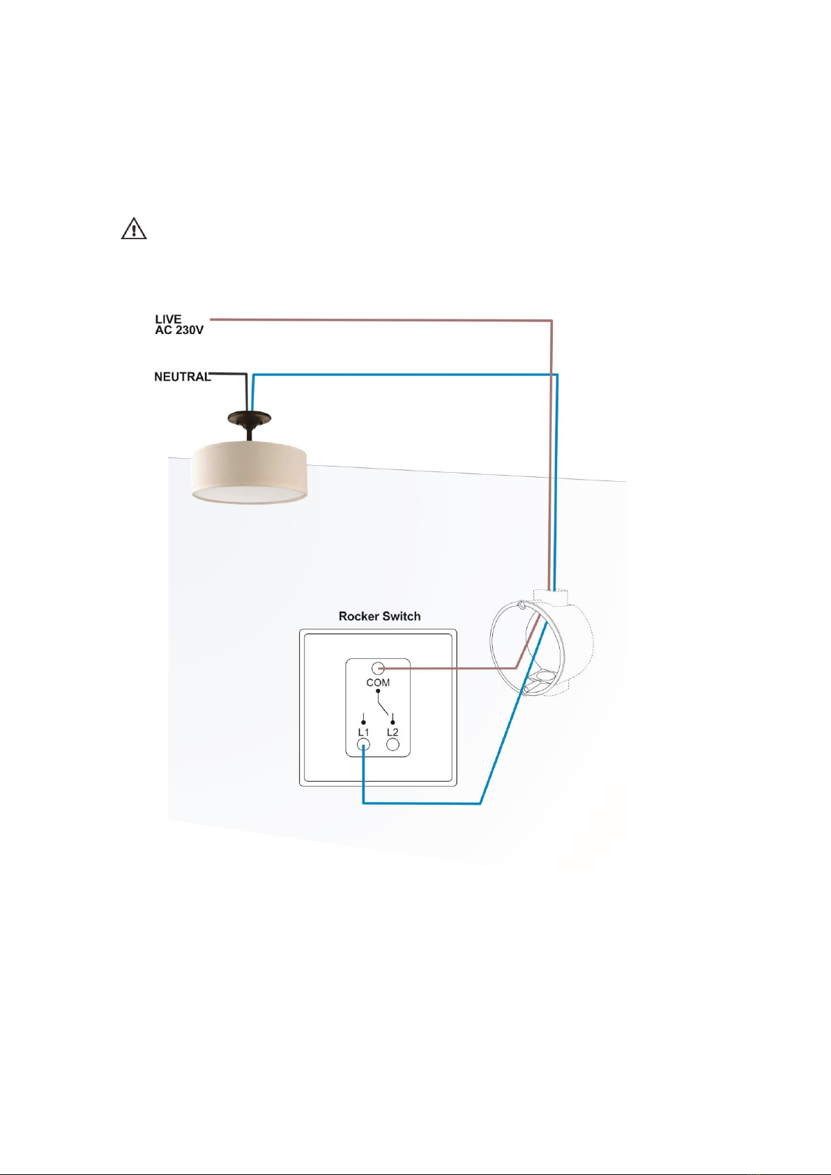
3.Installation - Wiring
Cut off main power before installing and wiring.
Current existing house wiring should be as below.
INSTALLATION - WIRING
5
Issue Date: 5/2/2020
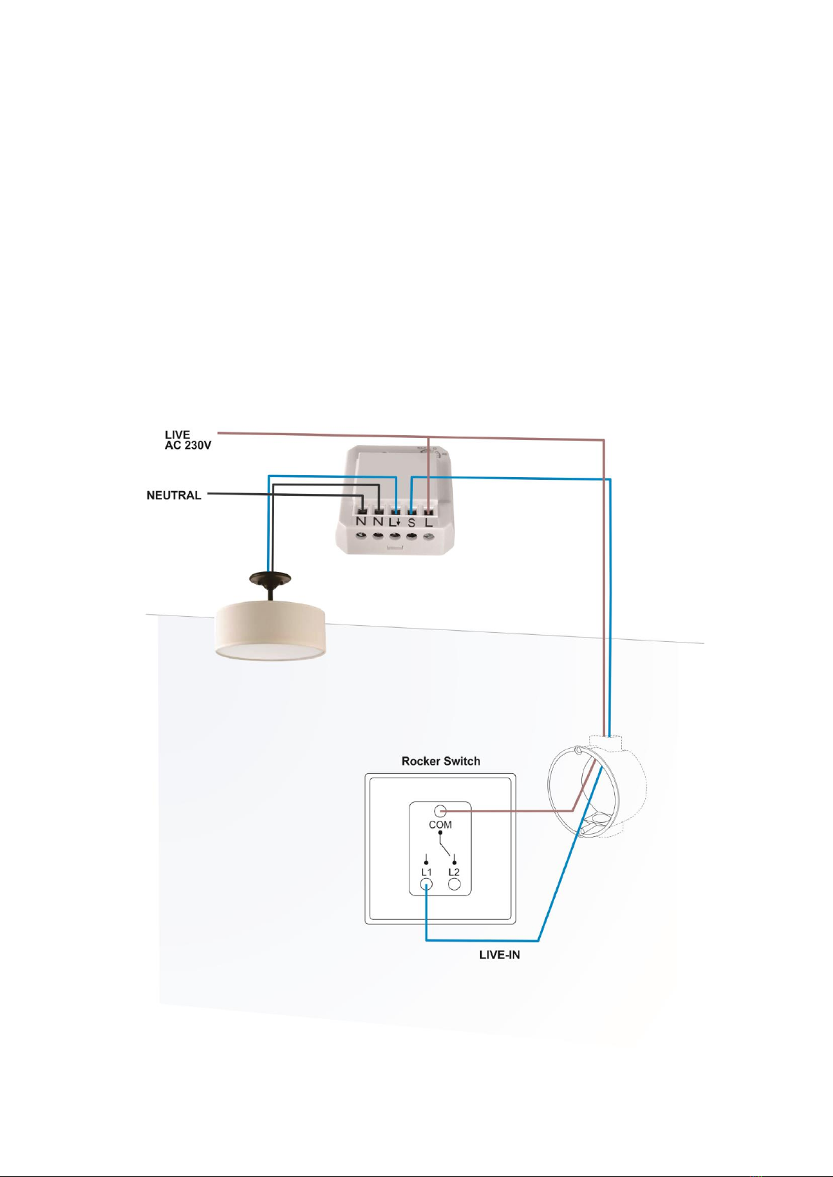
Add mini module with one way operation
1. Connect permanent Live wire into module terminal ‘L’.
2. Connect Neutral wire into module terminal ‘N’.
3. Connect wire from module terminal ‘ L& N’ to Load.
4. Connect switch Live wire from module terminal ‘S’ into switch ‘L1’ terminal.
5. Connect permanent Live wire into switch ‘Com’ terminal.
6. Connect back mains power supply.
INSTALLATION - WIRING
6
Issue Date: 5/2/2020
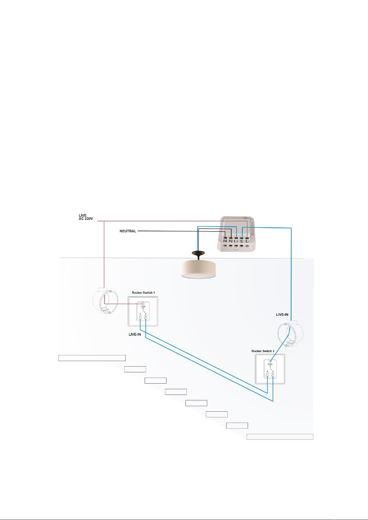
Add mini module with two way operation
Two Way Operation
1. Switch 1 and 2 must be connected together with wires into ‘L1 & L2’ terminal.
2. Connect permanent Live wire into module terminal ‘L’.
3. Connect Neutral wire into module terminal ‘N’.
4. Connect wire from module terminal ‘ L& N’ to Load.
5. Connect permanent Live wire into switch 1 ‘Com’ terminal.
6. Connect switch Live wire from module terminal ‘S’ into switch 2 ‘Com’
terminal.
7. Connect wire from module terminal ‘L& N’ to Load
8. Connect back mains power supply.
INSTALLATION - WIRING
7
Issue Date: 5/2/2020
4.Pairing / Un-pairing Device
PAIRING
Pairing using LEARNING MODE:
1. Press ‘Learn’ button once (LED on module will flash), this will enter learning
mode.
2. With a remote control press the ‘ON’ button; LED on module will flash to
confirm that the remote control is now paired.
NOTE: If no signal is received from a remote control within 12 seconds then the
module will automatically exit learning mode without pairing the device.
To exit learning mode manually, simply press the ‘Learn’ button again.
PAIRING / UN-PARING DEVICE

8
Issue Date: 5/2/2020
UN-PAIRING
Removing single Device:
1. Press ‘Learn’ once (LED on module will flash), this will enter learning mode.
2. With a remote control press the ‘OFF’ button intended to be un-paired; LED
on module will flash to confirm that the remote control is un-paired.
CLEARING ALL MEMORY
Removing all memory stored in the module.
1. On the module hold down the ‘Learn’ button for 6 seconds, LED on module
will flash.
2. Release button then press again, this will remove all memory stored in the
module.
PAIRING / UN-PARING DEVICE
9
Issue Date: 5/2/2020
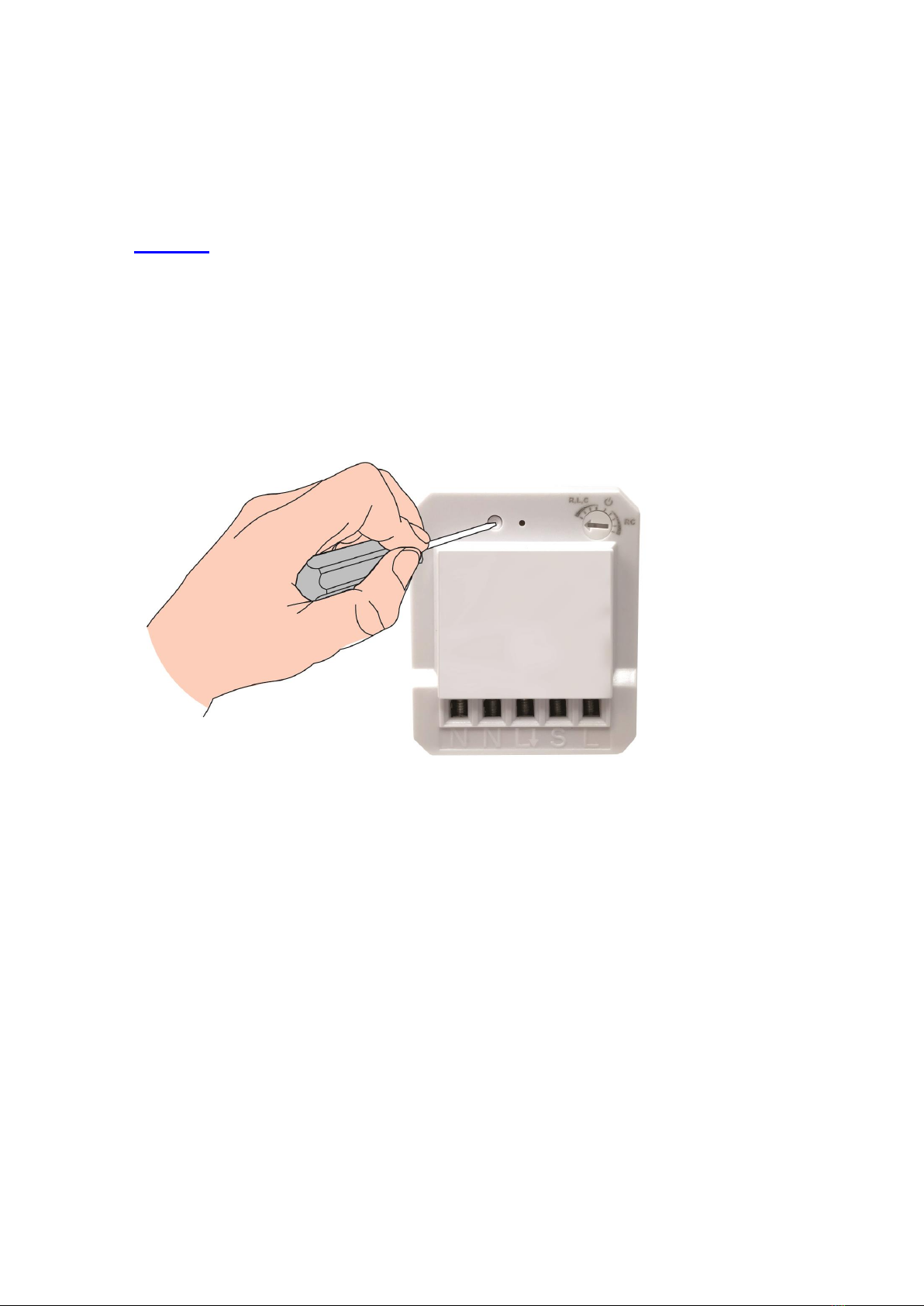
5.Non-Dimmable / Trailing & Leading Edge Setup
Initial factory pre-set is at ‘Leading Edge’ Position
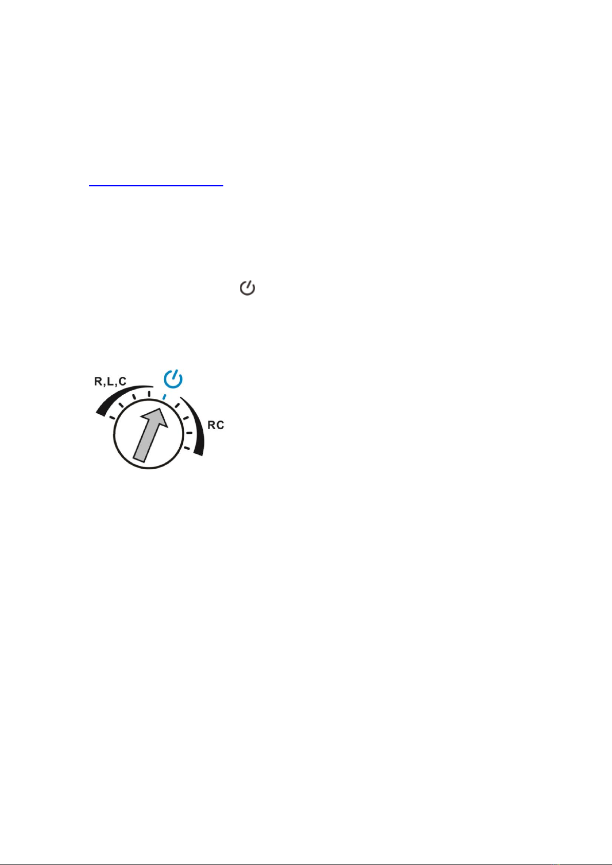
NON-DIMMABLE LOAD
On-Off Function for non dimmable load.
Benefit to change from dimmable to non dimmable load without changing the
module and operates normally for On-Off function.
⚫Adjust rotary switch to position, LED on module will quick flash to
confirm and connected load will light up at full brightness.
⚫This confirms the mini wall module is properly setup under On-Off Function.
NON-DIMMABLE / TRAILING & LEADING EDEGE SETUP
10
Issue Date: 5/2/2020
TRAILING EDGE /LEADING EDGE /MINIMUM BRIGHTNESS LEVEL
Adjust the rotary switch on the top light hand corner to select trailing or leading
edge by trimmer resistor.
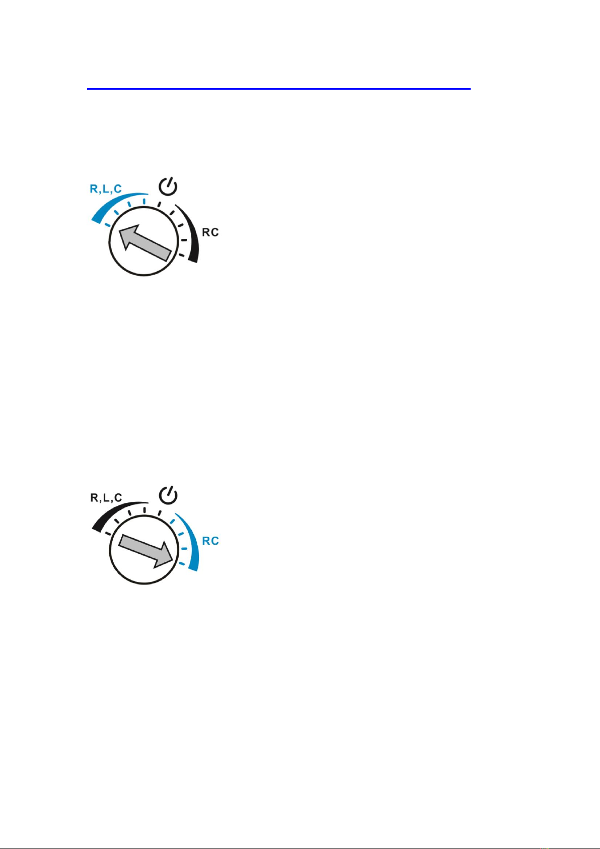
Leading Edge
⚫Adjust rotary switch counterclockwise to the very end of R,L,C position,
LED on module will blink once to confirm the mini wall module is properly
setup under leading edge.
⚫Slowly turn clockwise to adjust the minimum brightness level. If load flickers
or turns OFF during operation, adjust counterclockwise one level up until
the load lights up and do not flicker. Please adjust to the most suitable dim
level that you desire.
⚫During ON/OFF operation LED on module will flash once.
Trailing Edge
⚫Adjust rotary switch clockwise to the very end of RC position, LED on
module will blink once to confirm the mini wall module is properly setup
under Trailing Edge.
⚫Slowly turn counterclockwise to adjust the minimum brightness level. If load
flickers or turns OFF during operation, adjust clockwise one level up until
the load lights up do not flicker. Please adjust to the most suitable dim level
that you desire.
⚫During ON/OFF operation LED on module will flash twice.
NON-DIMMABLE / TRAILING & LEADING EDEGE SETUP
Indice
Altri manuali ARC Dimmer


