Arcan HJ1800AU Manuale utente

1 rev. 041814
Model HJ1800AU
1,800 kg Aluminum-Steel Hybrid Jack
For Technical Questions, Call: 1-800-879-7316
Warning information
This is the safety alert symbol. It is used to alert you
to potential personal injury hazards. Obey all safety
messages that follow this symbol to avoid possible
injury or death.
imPortant: rEaD tHESE inStrUCtionS BEforE oPErating
BEFORE USING THIS DEVICE, READ THIS MANUAL COMPLETELY AND THOROUGHLY, UNDERSTAND ITS OPERATING
PROCEDURES, SAFETY WARNINGS AND MAINTENANCE REQUIREMENTS.
It is the responsibility of the owner to make sure all personnel read this manual prior to using the device. It is also the responsiblity of the
device owner to keep this manual intact and in a convenient location for all to see and read. Contact Arcan for a replacement label if your
jack's label is not readable.
tHE natUrE of HaZarDoUS SitUationS
The use of Portable Automotive Lifting Devices are subject to certain hazards that cannot be prevented by mechanical means, but only
by the exercise of intelligence, care, and common sense. It is essential to have personnel involved in the use and operation of the device
who are careful, competent, trained, and qualified in the safe operation of the device and its proper use when servicing motor vehicles
and their components. Examples of hazards are dropping, tipping or slipping of loads caused primarily by improperly securing loads,
overloading, off-centered loads, use on other than hard level surfaces, and using equipment for a purpose for which it was not intended.
mEtHoDS to aVoiD HaZarDoUS SitUationS
• Theunliftedwheelsofthevehicleshouldbechocked.
• Loadshouldbecentrallylocatedontheheadcap.
• Nopersonshouldremaininavehiclethatisbeinglifted.
• Vehiclemanufacturerownersmanualshouldbeconsultedpriortoliftingofvehicle.
• Thehydraulicjackshouldbeusedforliftingandloweringonly.
• Useonlyhighqualityhydraulicoil.
• Inspectthejackbeforeeachuse.Donotusejackifdamaged,altered,modied,inpoorcondition,leakinghydraulicuid,orunstable
due to loose or missing components. Make corrections before using.
• Liftonlyonareasofthevehicleasspeciedbythevehiclemanufacturer.
• WeareyeprotectionthatmeetsANSIZ87.1andOSHAstandards.
• Donotusejackbeyonditsratedcapacity.
• Thisisaliftingdeviceonly.Immediatelyafterlifting,supportthevehiclewithjackstandscapableofsustainingtheloadbeforeworking
on the vehicle.
• Useonlyonahardlevelsurfacefreefromobstructionssothejackisfreetorepositionitselfduringliftingandloweringoperations.
• Centerloadonsaddle.Besuresetupisstablebeforeworkingonvehicle.
• Donotmoveordollythevehiclewhileonthejack.
• Donotusesaddleadaptersorsaddleextendersbetweenthestockliftingsaddleandtheload.
• DonotuseanyadaptersunlessapprovedorsuppliedbyArcan.
• Alwayslowerthejackslowlyandcarefully.
• Failuretoheedthesewarningsmayresultinfatalpersonalinjuryand/orpropertydamage.
ConSEQUEnCES of not aVoiDing HaZarDoUS SitUationS
Failure to read this manual completely and thoroughly, failure to understand its OPERATING INSTRUCTIONS, SAFETY WARNINGS,
MAINTENANCEINSTRUCTIONSandcomplywiththem,andfailuretocomplywiththeMETHODSTOAVOIDHAZARDOUSSITUATIONS
couldcauseaccidentsresultinginseriousorfatalpersonalinjuryand/orpropertydamage.
WARNING: Indicates a hazardous situation
which, if not avoided, could result in death
or serious injury.
WARNING
WARNING
WARNING
WARNING
ARCAN is a registered trademark of Powerstation LLC. All rights reserved.

HJ1800AU User Manual 2 rev. 041814
INSPECTION
Visual inspection should be made before each use of the jack, checking for leaking hydraulic uid and damaged, loose or missing parts. Any
jack which appears to be damaged in any way, is found to be badly worn, or operates abnormally MUST BE REMOVED FROM SERVICE
until necessary repairs are made.
SETUP
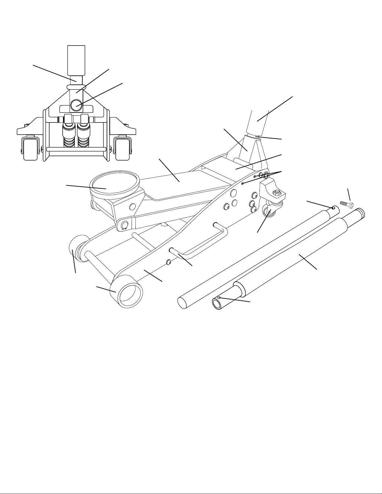
1. Remove 2-piece handle from box. Insert narrow portion of top handle into bottom handle, align top and bottom bolt holes, and secure with handle
bolt provided.
2. Grease the inside of the handle yoke so the handle will rotate freely inside the yoke. Remove the handle yoke screw. Insert the end of the lower handle
all the way in the handle yoke until it engages the release valve assembly. Secure the handle in the handle yoke by reinstalling the handle yoke screw
and tightening the screw. Rotate the handle to see if it is rotating the release valve assembly. Pull on the handle to make sure it is secured in the handle
yoke. If the release valve assembly is not rotating and/or the handle pulls out of the handle yoke, repeat step 2.
3. IMPORTANT: In most cases the jack should work normally right out of the box but it is not unusual for air to get trapped in the jack’s hydraulic system
during shipping and handling. There are several symptoms of an air trapped hydraulic system which include only partial incremental pump stroke,
jack will not lift load, jack will not sustain load or pumping feels spongy under load. The following procedure will purge air from the hydraulic system
and only needs to be done if experiencing the above mentioned conditions.
a) The saddle should be in its lowest position. Remove the four screws that secure the cover plate to the jack frame so the oil filler screw can be
removed from the hydraulic power unit reservoir tube.
b) Look inside the oil fill screw hole. You should be able to see the top of the power unit’s cylinder. The hydraulic fluid level should be no higher
than the top of the cylinder. Correct the fluid level if it is not at the proper height. CAUTION: In order to prevent seal damage and jack failure,
never use alcohol, hydraulic brake fluid, or transmission oil in the jack. Use hydraulic jack oil, a light turbine oil, Chevron Hydraulic Oil AW ISO
32 or Unocal Unax AW 150.
c) Close the release valve by turning the handle clockwise until it stops. Pump the jack against a load of at least 500 pounds (225 Kgs). After
the load is raised to maximum height, slightly turn the handle in a counterclockwise direction so the load is very slowly lowered, while
simultaneously and quickly pumping the handle 5 or 6 full incremental pump strokes. After pumping, lower the lift arm to its full rest position.
d) Install the oil fill screw. Rotate the handle in a clockwise direction until tight and pump the lift arm to maximum height without a load. Repeat steps
a) through d) until all the air has been purged from the system. Reinstall the cover plate.
IMPORTANT: Before attempting to raise any vehicle, check vehicle service manual for recommended lifting surfaces.
Saddle
Chassis
Side Handle
Lift Arm
Handle
Bumper
Handle Yoke Screw
Handle
Handle
Yoke
Handle
Yoke
Handle
Cover Plate
Screws
Rear
Casters
Upper
Handle
Hole
Lower
Handle
Bumper
Lower Handle Hole
Front
Wheels
Handle
Bolt

HJ1800AU User Manual 3 rev. 041814
OPERATING INSTRUCTIONS
This is the safety alert symbol used for the OPERATING INSTRUCTIONS section of this manual to alert you to potential personal
injury hazards. Obey all instructions to avoid possible injury or death. IMPORTANT: Before attempting to raise any vehicle, check
vehicle service manual for recommended lifting surfaces.
OPERATION
1. Put vehicle transmission in park or in gear and then apply the emergency brake.
To raise load: Turn the handle in a clockwise direction until tight. Position the jack under the load. Proceed to pump the handle
in order to raise the lift arm to the load. As the saddle at the end of the lift arm gets closer to the load, reposition the jack so the
saddle will contact the load rmly and the load is centered on the saddle. Make sure the saddle is correctly positioned. Raise the
load to the desired work height. Place jack stands of appropriate capacity at the vehicle manufacturers's recommended support
areas that provide stable support for the raised vehicle. DO NOT CRAWL UNDER VEHICLE WHILE LIFTING VEHICLE OR PLACING
OR REMOVING THE JACK STANDS! Once jack stands are positioned, turn the jack handle VERY SLOWLY in a counterclockwise
direction to lower the load to rest on the jack stands. Inspect the relationship between the jack stands and load to make sure the setup
is stable and safe. If the setup is not stable or safe, follow the preceding steps until corrected.
2. To lower load: Follow the procedures mentioned in "To raise load" section of the OPERATING INSTRUCTIONS in order to raise
the load off the jack stands. Once the load has cleared the jack stands, remove the jack stands from under the load and away
from the work area. Turn handle very slowly in a counterclockwise direction until the load is completely lowered to the ground.
Once the jack's lifting saddle has cleared the load, remove the jack from under the load. CAUTION: Keep hands and feet away
from the hinge mechanism of the jack.
PREVENTATIVE MAINTENANCE
This is the safety alert symbol used for the PREVENTATIVE MAINTENANCE section of this manual to alert you to potential
personal injury hazards. Obey all instructions to avoid possible injury or death.
1. Always store the jack in a well protected area where it will not be exposed to inclement weather, corrosive vapors, abrasive dust,
or any other harmful elements. The jack must be cleaned of water, snow, sand or grit before using.
2. The jack must be lubricated periodically in order to prevent premature wearing of parts. A general purpose grease must be applied to
caster wheels, front axle, elevator arm, handle base pivot bolts, release mechanism and all other bearing surfaces. Worn parts resulting
from inadequate or no lubrication are not eligible for warranty consideration. See page 4 for lubrication instructions.
IMPORTANT: In order to prevent seal damage and jack failure, never use alcohol, hydraulic brake uid, or transmission oil in the
jack. Use hydraulic jack oil, a light turbine oil, Chevron AW ISO 32 or Unocal Unax AW 150.
3. Every jack owner is responsible for keeping the jack labels clean and readable. Use a mild soap solution to wash external
surfaces of the jack but not any moving hydraulic components.
4. Inspect the jack before each use. Do not use the jack if any component is cracked, broken, bent, shows sign of damage or leaks
hydraulic uid. Do not use the jack if it has loose or missing hardware or components, or is modied in any way. Take corrective action
before using the jack again.
PROPER STORAGE
It is recommended that the jack be stored in a dry location with all wheels touching the ground on a relatively level surface.
TROUBLESHOOTING
Important: Service jacks are self-contained devices used for lifting, but not sustaining, a partial vehicular load. In accordance with ASME-
PALD Load Sustaining Test: “A load not less than the rated capacity…shall not lower more than 1/8" (3.18mm) in the rst minute, nor a total
of .1875" (4.76mm) in 10 minutes.” Lowering within this range is considered normal operation and is NOT a warrantable defect.
PROBLEM ACTION
1. Unit will not lift load. Purge air from hydraulic system by following procedure under SETUP.
2. Unit will not sustain load or feels “spongy” under load. Purge air from hydraulic system as above.
3. Unit will not lift to full height. Purge air from hydraulic system as above.
4. Unit will not lower completely. Check oil level. Make sure hydraulic system is not overfilled.
5. Handle tends to raise up while the unit is under load. Pump the handle rapidly several times to push oil past ball valves in
power unit.
6. Unit still does not operate. Contact customer service (page 6).

HJ1800AU User Manual 4 rev. 041814
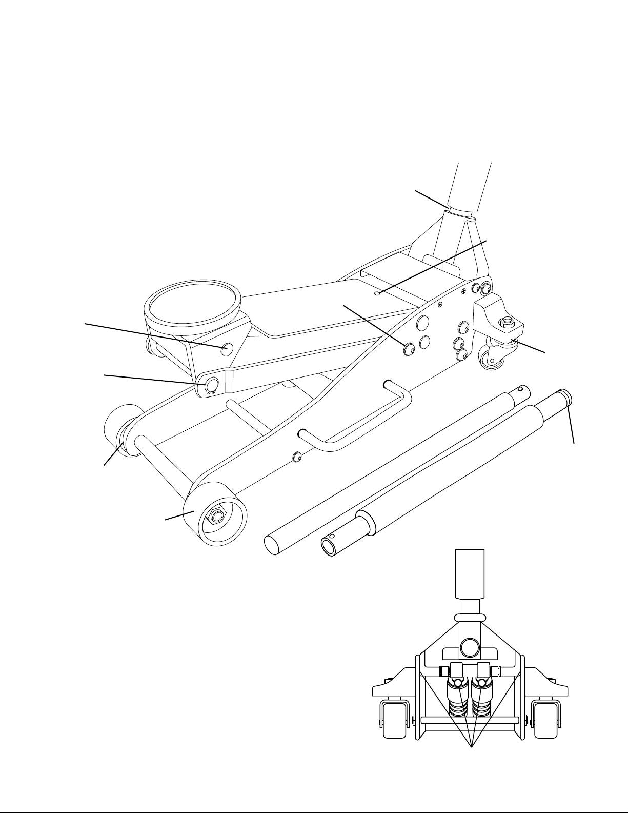
HYDRAULIC MAINTENANCE GUIDE
IMPORTANT: Service jacks are designed for lifting purposes only; always support raised load with jack stands.
REGULAR MAINTENANCE
MONTHLY or as necessary (depending on usage)
#1 Using a grease gun, add grease to grease tting in the lift arm pivot shaft.
(Use a multi-purpose NLGI type grease only.)
#2 Lubricate all linkages and pivot points.
(Use white lithium spray grease only.)
#3 Remove handle; lubricate handle receptacle and handle end.
(Use white lithium spray grease only.)
#4 Lubricate both rear casters bearings and both front wheels.
(Use white lithium spray grease only.)
Tighten all accessible hardware.
#2
#3
#4
#4
#4
#1
#2
#2
#3
#2

HJ1800AU User Manual 5 rev. 041814
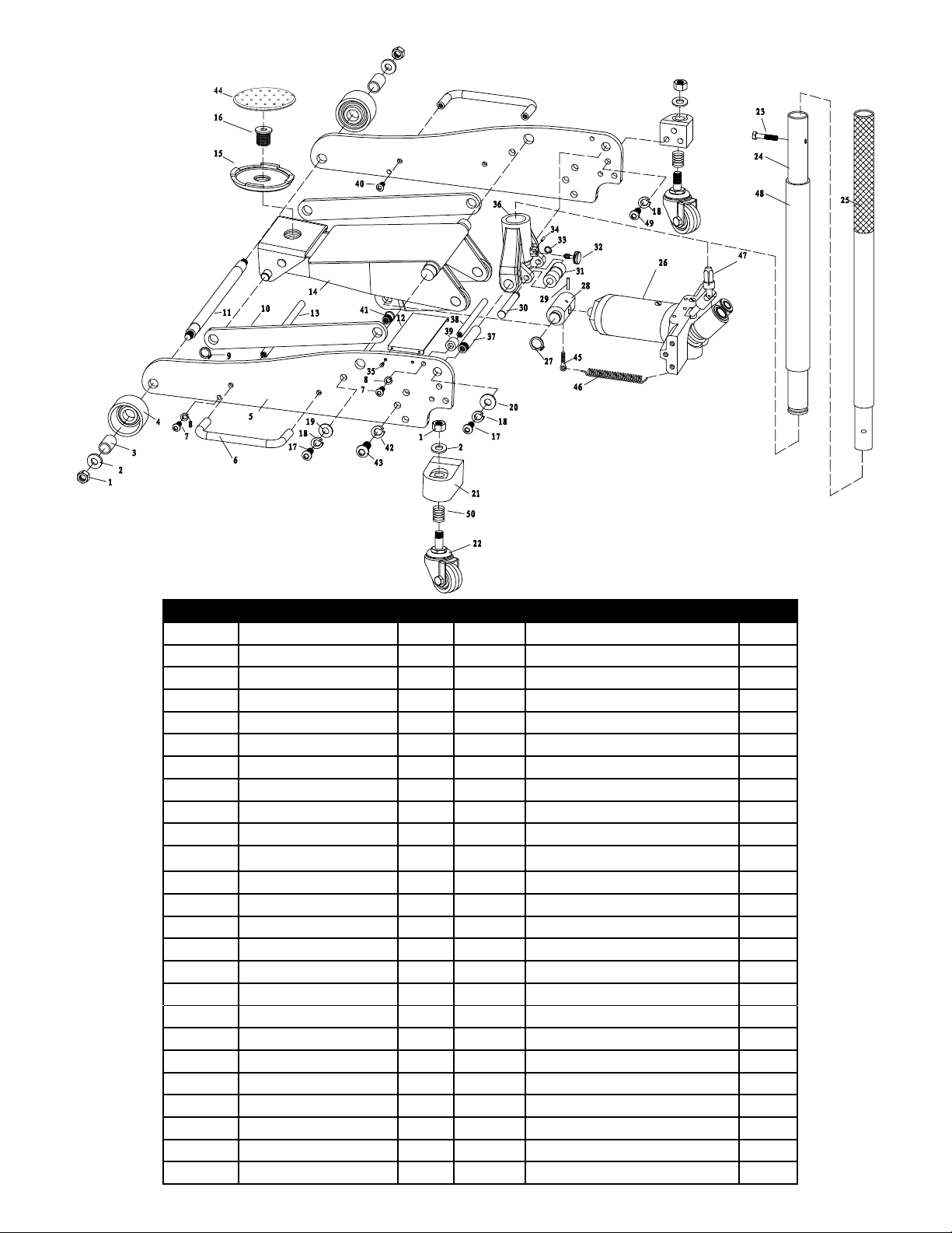
PARTS LIST AND DIAGRAM
ITEM NO DESCRIPTION QTY ITEM NO DESCRIPTION QTY
1 Locking Nut M12 4 26 Hydraulic Power Unit Assembly 1
2 Flat Washer 20 2 27 Retaining Ring 20 2
3 Front Wheel Bushing 2 28 Trunion 1
4 Front Wheel 2 29 Pin 4x40 1
5 Side Plate 2 30 Roller Bolt 1
6 Carrying Handle 2 31 Roller 1
7 Screw M8x25 4 32 Handle Yoke Screw 1
8 Washer 8 4 33 Retaining Ring 12 1
9 Retaining Ring 16 2 34 Spring Pin 3x14 1
10 Long Linkage 2 35 Screw M5x16 4
11 Front Wheel Axle 1 36 Handle Yoke 1
12 Covering plate 1 37 Handle Yoke Bolt 2
13 Spacer Bar 1 38 Stop Rod 1
14 Lift Arm Assembly 1 39 Rubber Guard 2
15 Saddle 1 40 Screw 8x25 4
16 Saddle screw 1 41 Linkage Bolt 2
17 Screw M10x20 4 42 Spring Washer 12 6
18 Tooth Washer 10 10 43 Screw M12x25 6
19 Flat Washer 10 2 44 Saddle Pad 1
20 Flat Washer 10 2 45 Trunion Screw 2
21 Rear Caster Bracket 2 46 Return Spring 2
22 Rear Caster Assembly 2 47 Release Valve Assembly 1
23 Screw M6x35 1 48 Handle Bumper 1
24 Lower Handle 1 49 Screw 10x25 6
25 Upper Handle 1 50 Spring 2

HJ1800AU User Manual 6 rev. 041814
LIMITED WARRANTY
POWERSTATION, LLC WARRANTS TO ITS CUSTOMERS THAT THE COMPANY’S POWERSTATION, LLC
BRANDED PRODUCTS ARE FREE FROM DEFECTS IN WORKMANSHIP AND MATERIALS.
PowerStation, LLC will repair or replace its PowerStation, LLC branded products which fail to give satisfactory service due to
defective workmanship or materials, based upon the terms and conditions of the following described warranty plans attributed to that
specic product. This product carries a ONE-YEAR warranty. During this warranty period, PowerStation, LLC will repair or replace at our
option any part or unit which proves to be defective in material or workmanship.
Other important warranty information:
This warranty does not cover damage to equipment or tools arising from alteration, abuse, misuse, damage and does not cover any repairs
or replacement made by anyone other than PowerStation, LLC.The foregoing obligation is PowerStation, LLCs’ sole liability under this or
any implied warranty and under no circumstances shall we be liable for any incidental or consequential damages.
Note:
Some states do not allow the exclusion or limitation of incidental or consequential damages, so the above limitation or
exclusion may not apply to you. If you have any questions about warranty service, please contact PowerStation, LLC. This warranty gives
you specic legal rights and you may also have other rights which vary from state to state.
1-800-879-7316
Monday - Friday 8:30am to 5:30pm EST
P.O. Box 1203
Travelers Rest, South Carolina 29690
Costco Wholesale Australia Pty Ltd,
17-21 Parramatta Road, LIDCOMBE, NSW, 2141, AUSTRALIA
www.costco.com.au
Our goods come with guarantees that cannot be excluded under the Australian Consumer Law. You are entitled to a replacement or refund for
a major failure and for compensation for any other reasonably foreseeable loss or damage. You are also entitled to have the goods repaired
or replaced if the goods fail to be of acceptable quality and the failure does not amount to a major failure.
SPECIFICATIONS
Capacity: 1,800 kgs.
Minimum Lift Height: 101.6 mm
Maximum Lift Height: 470 mm
Lifting Range: 369 mm
Caster Wheel Size: 46 mm x 23 mm
Front Wheel Size: 66 mm x 41 mm
Saddle Diameter: 117 mm
Handle Length: 1143 mm
Dimensions: 610 mm x 302 mm x 152 mm
Net Weight: 26 kgs.
Indice
Altri manuali Arcan Jack

Arcan
Arcan A20018 Manuale utente

Arcan
Arcan BLACKLINE ALJ3TB Manuale utente

Arcan
Arcan ALFJ48 Manuale utente

Arcan
Arcan XL325R Manuale utente

Arcan
Arcan BLACKLINE XL35B Manuale utente

Arcan
Arcan BLACKLINE XL40B Manuale utente

Arcan
Arcan AJS3T Manuale utente

Arcan
Arcan XL3000A Manuale utente

Arcan
Arcan A20015 Manuale utente

Arcan
Arcan XL3000 Manuale utente

Arcan
Arcan XL35R Manuale utente

Arcan
Arcan ALJ2T Manuale utente

Arcan
Arcan A20001 Manuale utente

Arcan
Arcan A20002 Manuale utente

Arcan
Arcan CRJ30 Manuale utente

Arcan
Arcan XL20 Manuale utente

Arcan
Arcan Blackline XL2TB Manuale utente

Arcan
Arcan XL325G Manuale utente

Arcan
Arcan BLACKLINE ALJ2TB Manuale utente

Arcan
Arcan ALJ3T Manuale utente