Arduino Nixie Clock v6 Manuale utente

Arduino Nixie Clock v6
Operating Instructions
Description
The Arduino Nixie Clock is a beautiful mix of old and new, resulting in a high accuracy, low power clock
which will be a talking point in your home.
The clock has the following features:
•Battery backed, temperature compensated, high accuracy clock. The accuracy is Accuracy 2ppm
from 0°C to +40°C. (Maximum 1 minute per year).
•The battery life should be 3 years in normal use.
•Retains the date and time even when turned off (not just for a few minutes, but for as long as the
battery lasts)
•Leap Year Compensation Valid Up to the year 2100
•Based on the Arduino micro-controller: Easy to program an well documented.
•Open source hardware and software. Nothing is hidden in this clock.
•You may modify and load the software with a normal PC
•Low power consumption.
•Anti Cathode Poisoning (ACP) makes sure that the tubes will stay healthy for many years with no
intervention from you.
•All settings are stored in non-volatile memory. Once they are set, they are remembered forever, or
until you change them again.
•RGB back lighting allows you to set the the color of the back lighting to practically any color you
desire.
•Ambient light sensing, with automatic tube dimming, which sets the tube and LED brightness
according to the light conditions. The tubes could be disturbing during the night if they are left at
full brightness.
•Absolutely silent operation. Some Nixie clocks emit an irritating “buzz” or “hiss” which is especially
annoying if you keep the clock in a bedroom.
•Long tube life: The multiplexed display and automatic dimming used in this design extends the life
of the tubes indefinitely. Other designs run the tubes too “hard”, and this causes a rapid
degradation in the useful life of the tube.
General
The clock has different modes of operation, which you select using the pushbutton. When you start the
clock up th very first time, it will start in “Time Display Mode”. We set it up to be the right time for where
the clock is being shipped to, so in the best case you will not even need to set the clock the first time!
The other modes of operation are described in the following sections.
Safety
The voltages produced in the High Voltage circuit can reach peaks of 400V! Take precautions not to
electrocute yourself! If you are not sure what this means, please do not use this clock and return it for a
full refund.
A shock from the clock high voltage circuit is at least a nasty bite. At worst it can kill you.
We decline any responsibility in the case of injury or death.
REPEA : If you are not sure, please do not use the clock.
ime Display Mode
Normally, the clock will show the time. To show additional information press the button with a “short”
press. Each press cycles through the following information. After 5 seconds, the display will revert to the
normal time display.
Mode Description Values
Date Date. The current date will be shown.
Temp emperature. The current internal temperature inside the clock
case will be shown in degrees Celsius. If this goes above 40, you
should consider ventilating the case, because the temperature
compensation is not able to work at such high voltages, and the
clock life may be reduced, and the time may drift.
Light Ambient Light Reading. This shows the current ambient light
reading from the LDR (light dependent resistor). It is a normalized
value, and goes between 100 (dark) to 999 (bright). This controls the
dimming of the tubes.
100: dark
999: bright
the date, press the button with a “short” press. Press the button again with a “short” press to show the
temperature.
Setting Mode
To enter setting mode, press the button for more than 1 second (“medium press”). The “tick” LED will start
to flash instead of pulse. The number of consecutive flashes indicates the mode you are in.
Each medium press of more than 1 second will move the setting mode onto the next. When you finish the
setting modes, the clock returns to normal time display mode.
o exit the setting mode before going through all the options, press the button for more than 2 seconds
(“long press”). The “tick” LED will start to pulse again. Another way of exiting is to cycle through all of the
setting options, after which you will return to time mode.
To change a setting, press the button for less than one second, and then release it (“short press”).
Mode Description Values
0ime mode. This is the normal mode and displays the time. It is the
normal start up mode of the clock. If you do nothing. The clock is in
this mode.
In this mode a short press cycles through the values given in “Time
Display Mode”, but always returns to the standard time display after
5 seconds.
1Set minutes. Each short press will advance the minute. The
minutes roll over back to 0 ffter reaching 59 minutes. Each time you
set the minute, the seconds is reset to 0.
2Set Hours. Each short press will advance the hour. The hours roll
over back to zero after reaching 12 or 24 (depending on the 12/24
hours mode).
3Set Day. Each short press will advance the day. The day roll over
back to one after reaching the maximum number of days in the
month.
4Set Month. Each short press will advance the month. The month
roll over back to zero after reaching 12.
5Set Year. Each short press will advance the year. The year roll over
back to 2015 after reaching 2099.
6Fade Speed Slower. Each short press will make the fade speed
between digits slower.
Default: 50
Max: 200
Min: 20
7Fade Speed Faster. Each short press will make the fade speed
between digits faster.
Default: 50
Max: 200
Min: 20
8HV Generator Frequency Higher. This controls the internal
frequency of the HV generator. The lower the number, the higher
the frequency of the HV generation. Normally you will not have to
adjust this, but with some tubes, adjusting it can stop “flickering” in
the filaments.
Before leaving the clock for long periods with a new setting, check
that IRF740 MOSFET is not running too hot.
Default: 200
Max: 400
Min: 100
9HV Generator Frequency Lower. This controls the internal
frequency of the HV generator. The higher the number, the lower
the frequency of the HV generation. Normally you will not have to
adjust this, but with some tubes, adjusting it can stop “flickering” in
the filaments.
Before leaving the clock for long periods with a new setting, check
that IRF740 MOSFET is not running too hot.
Default: 200
Max: 400
Min: 100
10 Scroll-back Speed Slower. Each short press will make the “scroll-
back” speed slower.
Default: 4
Max: 40
Min: 1
11 Scroll-back Speed Faster. Each short press will make the “scroll-
back” speed faster.
Default: 4
Max: 40
Min: 1
12 12 or 24 hour time. The hours are displayed in 12 or 24 hour
mode.
“1” = 12 hour
“0” = 24 hour
13 Blank leading “0”. Blank out the leading “0” from single digit hours. “1” = blank
“0” = don't blank
14 Scroll back. Use the scroll back (rapid count down) effect when
changing from “9” to “0”.
“1” = enable
“0” = disable
15 Red Channel Intensity. Sets the maximum intensity of the red
channel back light. This will be dimmed according to the display
dimming.
Default: 255
Max: 255
Min: 0
16 Green Channel Intensity. Sets the maximum intensity of the green
channel back light. This will be dimmed according to the display
dimming.
Default: 255
Max: 255
Min: 0
17 Blue Channel Intensity. Sets the maximum intensity of the blue
channel back light. This will be dimmed according to the display
dimming.
Default: 255
Max: 255
Min: 0
18 Current case temperature. Show the current temperature inside
the case (used as part of the temperature compensation for the
clock crystal).
19 Clock version. Show the clock software version. In this version, will
show “0006”.
20 Digit est. Will roll through all digits on all locations to check that
the display is healthy.
Display Blanking Mode
During display blanking mode, the “tick” LED will continue to pulse at low intensity, telling you that the
clock is still running. In order to display the time, just press the button, and the time will be displayed.
If you want to enable the display for the rest of the day, do a long press of the button.
ube Healing Mode
After a long period of time, tube filaments which are not often used (e.g. the “9” on the tens of hours or
minutes) can get dim, despite the ACP that is regularly done.
If you make a “super-long” press of the button (more than 8 seconds), the clock will enter filament healing
mode. All the power will be placed through a single filament of a single digit to clean it. A short press will
change the selected filament.
Another super-long press or cycling through all the filaments will return the clock to normal.
Caution! Don't leave a single filament in this state for an extended period of time. It is a harsh process,
and may damage the tube if you leave it in this mode for too long. Normally a few minutes will restore the
cathode digit.
Factory Reset
To reset the clock back to initial settings, hold down the button while powering on and hold for at least 3
seconds. The “tick” LED will flash 10 times to signal that the reset has been done.
Everything will be reset back to the factory default state.
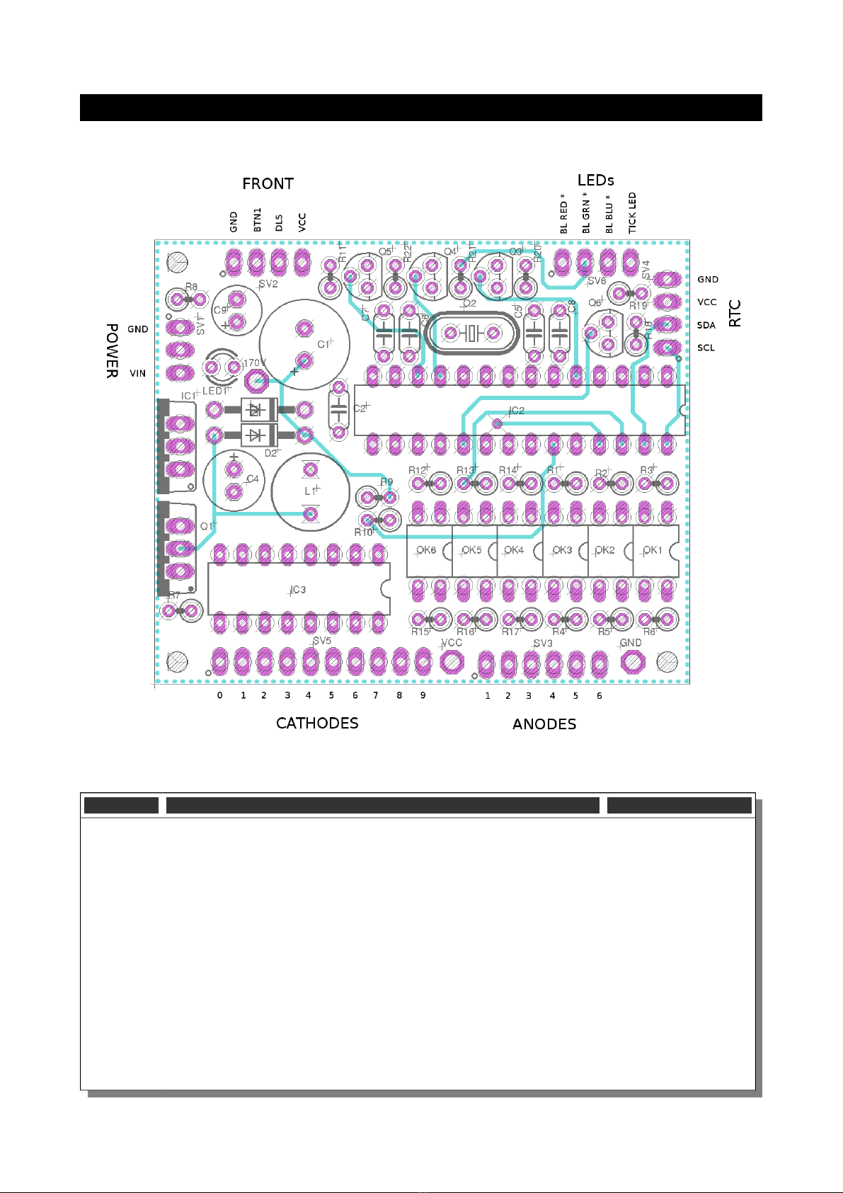
Board layout
For reference, the board layout is as shown (viewed from the top):
The connections are:
Connector Description Values
POWER Power.
External power should be applied to the board with this connector.
Any DC input source is possible, from 7V – 12V. Higher voltages may
be possible, but could cause the digits to flicker is the voltage is too
high.
The absolute maximum input voltage is 30V. Any higher voltage
than this will damage the board!
The input is protected against the input being connected reversed.
The input current ranges from 300mA to 1A depending on the size
of the tubes and the number of LEDs you are driving.
GND: The negative side of the input supply

VIN: The positive side of the input supply
FRONT Front Panel.
These are the controls that go on the front panel: The input button
and the Light Dependent Resistor to detect ambient light.
GND: The “ground”. One lead of the button and one lead of the LDR
are connected to this.
B N1: The other lead of the button is connected to this input
DLS: The other lead of the LDR is connected to this
VCC: Regulated 5V output to drive any LEDs or lighting.
LEDs The LEDs are connected to these sink terminals. To connect up you
take the positive sides of the LEDs to either VIN or VCC and connect
the negative sides of the LEDs to these termionals.
BL RED *: PWM cathode connection for the back light RED channel.
BL GRN *: PWM cathode connection for the back light GREEN
channel.
BL BLU *: PWM cathode connection for the back light BLUE
channel.
ICK LED: Cathode connection for the blinking “tick” LED.
RTC The connection for the RTC (Real Time Clock) module. Connect this
to the approriately marked terminals on the RTC module.
CATHODES The terminals to the cathodes (individual digits “0” - “9”) for each
tube.
ANODES The terminals to the anodes for each tube.
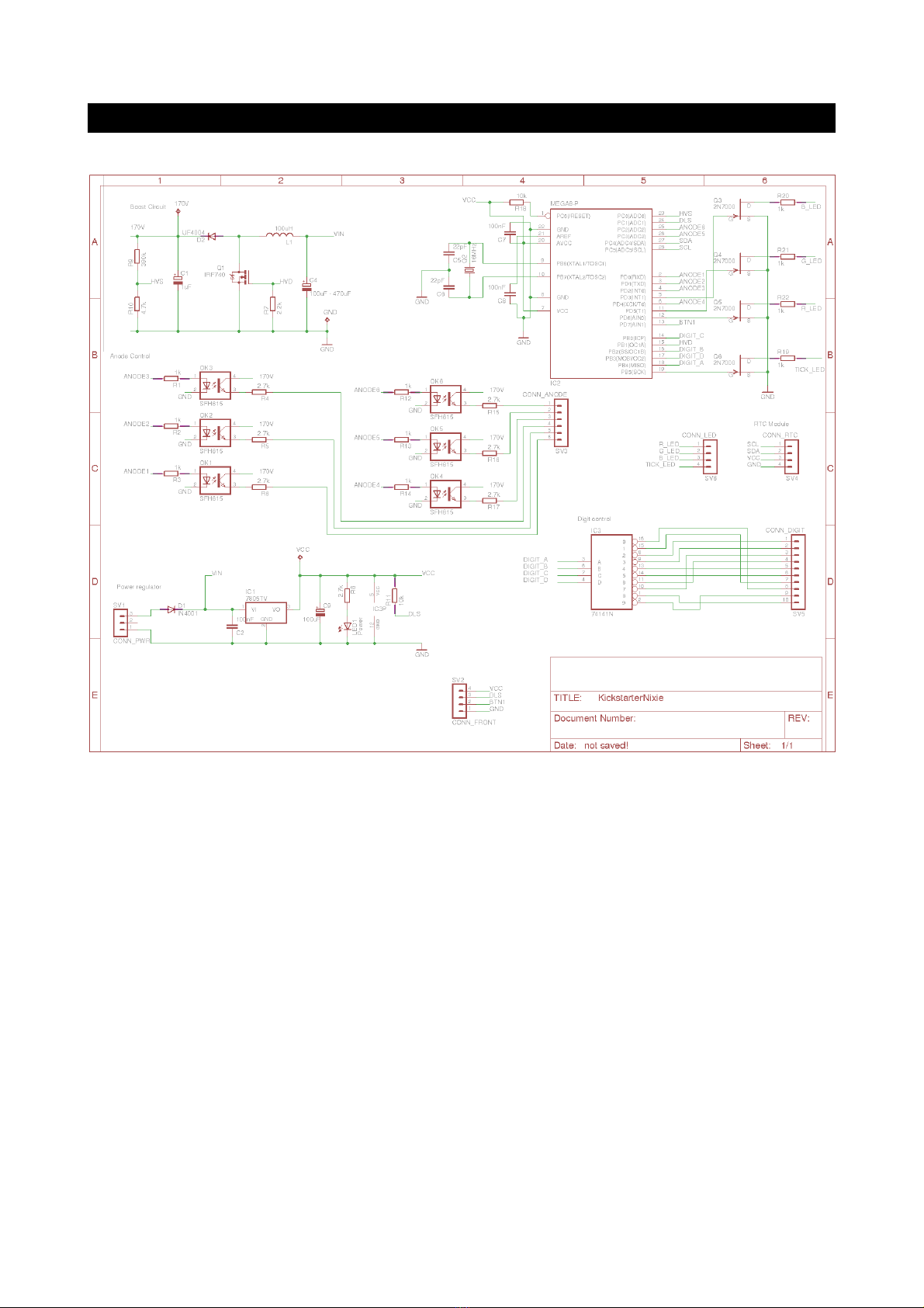
Schematic
Below is the schematic for the clock.

And for the external components, showing how they are connected.
The LDR and switch are connected to ground (pin 1).
The LEDs are driven preferably from VCC (regulated 5V).

Construction
Kit Contents:
When you unpack the kit, you should find the following contents:
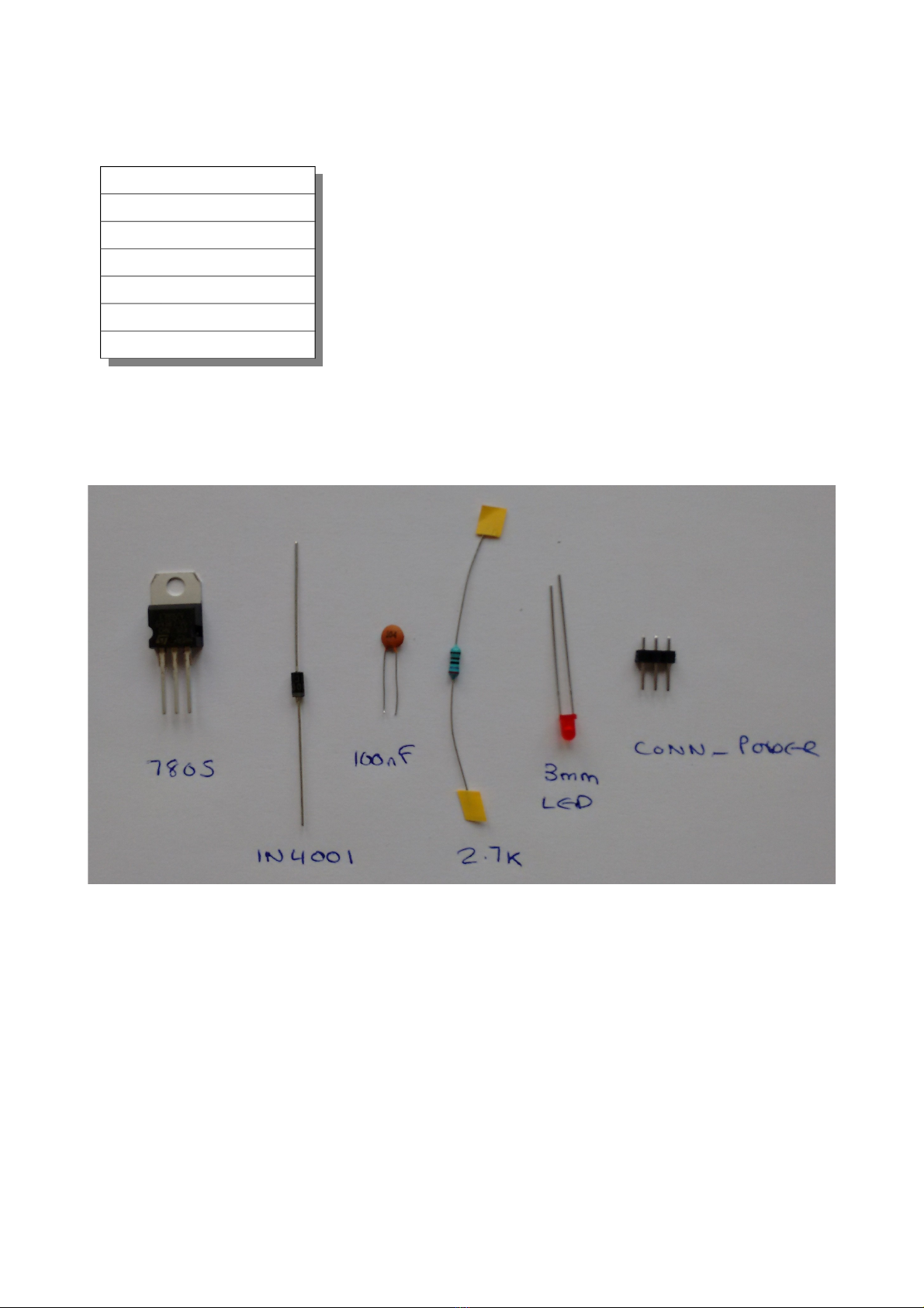
Low Voltage Circuit:
Parts List:
D1 IN4001
C2 100nF
IC1 7805TV
C9 100uF
R8 2.7k
LED1 LED3MM
SV1 CONN_POWER
The Low Voltage circuit is a very traditional voltage regulator using a linear regulator. It's job is to reduce
the external voltage from the power adapter down to a known and stable 5V to drive the micro-controller.
Put the parts on the board in the marked locations in the order they appear on the list.
Notes:
•D1 and D2 look very similar, but have different jobs to do. Be careful to get the 1N4001 and not the
UF4004.
•D1 should be placed so that the white stripe on the body lines up with the white stripe on the
board.
•C9 must go the right way round. The negative side is marked with a stripe.
•The LED must go with the right polarity. The + side has a flat on it, and has the shorter lead.
•Put IC1 so that the metal tab lines up with the white stripe on the board. The metal side faces to
the
outside
of the board.
Once all the components are on the board, hook up the power, and check that the LED comes on. Check
also that the voltage is 5V between the “GND” test point and the “VCC” test point.
Indice
Altri manuali Arduino Orologio


