Argo AQUA UNIT AUBV V2 Manuale utente

AQUA UNIT
Indoor unit - Inverter split air to water heat pump
Unità interna - Pompa di calore split Inverter aria / acqua
Unité intérieure - Pompe à chaleur split Inverter air / eau
37.4255.226.01 03/2023
AUBV V2
AUCV V2
AUDV V2
EN
IT
OPERATING AND INSTALLATION INSTRUCTIONS
ISTRUZIONI D’USO E INSTALLAZIONE
NOTICE D’UTILISATION ET INSTALLATION FR
EN
22
CONTENTS
1 - Generalities . . . . . . . . . . . . . . . . . . . . . . . . . . . . . . . . . . . . . . . . . . .4
2 - Presentation . . . . . . . . . . . . . . . . . . . . . . . . . . . . . . . . . . . . . . . . . .5
3 - Installation. . . . . . . . . . . . . . . . . . . . . . . . . . . . . . . . . . . . . . . . . . . .7
4 - Connections . . . . . . . . . . . . . . . . . . . . . . . . . . . . . . . . . . . . . . . . . .9
5 - System wiring diagrams . . . . . . . . . . . . . . . . . . . . . . . . . . . . . . . .12
6 - Starting . . . . . . . . . . . . . . . . . . . . . . . . . . . . . . . . . . . . . . . . . . . . .18
7 - Wired controller installation . . . . . . . . . . . . . . . . . . . . . . . . . . . . .22
8 - Wired controller presentation and operation instructions . . . . . .28
9 - Maintenance instructions . . . . . . . . . . . . . . . . . . . . . . . . . . . . . . .34
10 - Electrical diagram . . . . . . . . . . . . . . . . . . . . . . . . . . . . . . . . . . . . .35
11 - Auto-diagnosis table. . . . . . . . . . . . . . . . . . . . . . . . . . . . . . . . . . .36
REGULATION (EU) No. 517/2014 - F-GAS
The unit contains R410A, a fluorinated greenhouse gas
with a global warming potential (GWP) of 2087.50.
Do not release R410A into the atmosphere.
Power Supply:
220 - 240 V ~ 50 Hz
IMPORTANT!
Please read before installation
Installation of these products must be carried out by qualified personnel in accordance with European regulations
303/2008 and 517/2014.
This system meets strict safety and operating standards.
For the installer or service person, it is important to install or service the system so that it operates safely and efficiently.
To begin the warranty, the product must be started by a service center Argoclima S.p.A.
Recommendations
• The personnel responsible for receiving the unit must conduct a visual inspection in order to identify all damage
to which the unit may have been subjected during transport: refrigerating circuit, electrical cabinet, chassis and
cabinet.
• During installation, troubleshooting and maintenance operations, never use the pipes as a step: under the stress,
the pipes may break and the refrigerant may cause serious burns.
For safe installation and trouble-free operation, you must:
• Carefully read this instruction booklet before beginning.
• Follow each installation or repair step exactly as shown.
• Observe all local, state and national electrical (and safety) codes.
• Pay close attention to all warning and caution notices given in this manual.
• Supply the unit with a dedicated electrical line.
• Make install the unit by qualified personnel, in possession of license F-GAS.
• Before installation, check that the voltage of the electric supply in your home or office is the same as the voltage
shown on the nameplate.
This symbol refers to a hazard or unsafe practice which can result in severe personal injury or death.
This symbol refers to a hazard or unsafe practice which can result in personal injury or product or property damage.
WARNING
CAUTION
EN
33
If necessary, get help
These instructions are all you need for most installation sites and maintenance conditions.
If you require help for a special problem, contact our sale/service outlet or your certified dealer for additional
instructions.
In case of improper installation
The manufacturer shall in no way be responsible for improper installation or maintenance service, including failure
to follow the instructions in this document.
SPECIAL PRECAUTIONS
• During installation, connect before the hydraulic and refrigerant system and then the wiring one; proceed in the
reverse order when removing the unit.
ELECTRICAL SHOCK CAN CAUSE SEVERE PERSONAL INJURY OR DEATH.
ONLY QUALIFIED, EXPERIENCED ELECTRICIANS SHOULD ATTEMPT TO WIRE THIS SYSTEM.
• Do not supply power to the unit until all wiring and tubing are completed or reconnected and checked, to ensure
the grounding.
• Highly dangerous electrical voltages are used in this system. Carefully refer to the wiring diagram and these
instructions when wiring.
Improper connections and inadequate grounding can cause accidental injury and death.
• Ground the unit following local electrical codes.
• The Yellow/Green wire cannot be used for any connection different from the ground connection.
• Connect all wiring tightly. Loose wiring may cause overheating at connection points and a possible fire hazard.
• Do not allow wiring to touch the refrigerant tubing.
• Do not use multicore cable when wiring the power supply and control lines. Use separate cables for each type of
line.
When transporting
Be careful when picking up and moving the unit. Get a partner to help, and bend your knees when lifting to reduce
strain on your back. Sharp edges or thin aluminium fins on the unit can cut your fingers.
When installing
... In a room
Properly insulate any tubing run inside a room to prevent “sweating”, which can cause dripping and water damage
to walls and floors.
... In a wall or floor
Make sure they are strong enough to hold the unit weight. It may be necessary to build a strong wooden or metal
frame to provide added support.
... In moist or uneven locations
Use a raised concrete base to provide a solid level foundation for the unit.
This prevents damage and abnormal vibrations.
... In area with strong winds
Securely anchor the unit down with bolts and a metal frame. Provide a suitable air baffle.
... In a snowy area
Install the unit on a raised platform that is higher than drifting snow. Provide snow vents.
When connecting refrigerant tubing of Emix / Emix-Tank
• Use the flare method for connecting tubing.
• Apply refrigerant lubricant to the matching surfaces of the flare and union tubes before connecting them; screw
by hand and then tighten the nut with a torque wrench for a leak-free connection.
• Check carefully for leaks before starting.
• Insulate the tubes with foamed polyethylene (min. thickness 8mm).
When connecting hydraulic tubing
• Keep all tubing runs as short as possible.
• Insulate the tubing.
• Check carefully for leaks before starting.
When servicing
• Turn the power OFF at the main power board before opening the unit to check or repair electrical parts and wiring.
• Keep your fingers and clothing away from any moving parts.
• Clean up the site after the work, remembering to check that no metal scraps or bits of wiring have been left inside
the unit being serviced.
• Ventilate the room during the installation or testing the refrigeration system; make sure that, after the installation,
no gas leaks are present, because this could produce toxic gas and dangerous if in contact with flames or heat-
sources.
When wiring
WARNING

EN
44
OPERATING CONDITIONS
1 - GENERALITIES
Water system pressure
Minimum: 1,5 bar
Maximum: 2,0 bar
Water temperature
The maximum allowable water inlet temperature of the heat pump is 75 ° C
Water volume of the system (to be compulsorily checked)
Minimum: AUBV V2: 40 litres (*)
AUCV V2: 80 litres (*)
AUDV V2: 80 litres (*)
Maximum:dimension the expansion vessel according to the maximum volume of water, the maximum
water temperature and the plant static height.
(*) If the water volume of the system (plant and product) is below the minimum, a buffer tank must be installed.
For the minimum water volume, consider the volume continuously connected to
the heat pump (don’t consider the volumes which could be isolated by automatic valves).
Operating limits Maximum temperature of water outlet
Outdoor ambient temperature
Heating: -20°C / +35°C
Cooling: +10°C / +47°C 58
-20 5
-10
55
35
10
50
Water outlet temperature (°C)
Outdoor air temperature (°C)

EN
55
2 - PRESENTATION
2.1 - DESCRIPTION OF THE PARTS
1 - Heat exchanger.
3 - Air vent valve.
7 - Water circulator.
8 - Expansion vessel.
9 - Refrigerant pressure transducer.
10 - Safety valve.
11 - Water ow sensor (owmeter).
12 - Water inlet connection.
13 - Water outlet connection.
15 - Safety valve drain connection.
16 - Flare refrigerant gas connector.
17 - Flare refrigerant liquid connector.
18 - Electrical cable passages.
19 - Front panel.
21 - Electrical box.
22 - PCB.
23 - Terminal blocks.
24 - Wired controller (obligatory).
Materials:
- Copper piping.
- Stainless steel water heat exchanger.
- Painted sheet metal cabinet.
1
3
7
9
11
12 13
15
16 17
10
18
8
21
22
23
19
ACCESSORIES SUPPLIED WITH THE UNIT
DHW SENSOR
INDOOR 123
WIRED CONTROLLER
(TO BE PURCHASED SEPARATELY)
24

EN
66
2.2 - DIMENSIONS AND WEIGHT
AUBV V2 AUCV V2 AUDV V2
1Water inlet connection 1” M 1” M 1” M
2Water outlet connection 1” M 1” M 1” M
3Condensate drain connection ø 16mm ø 16mm ø 16mm
4Gas refrigerant connection 1/2” 1/2” 5/8”
5Liquid refrigerant connection 1/4” 1/4” 3/8”
6Holes for electric cables - - -
Model Weight (kg)
AUBV V2 25
AUCV V2 27
AUDV V2 28
REAR VIEW FRONT VIEW SIDE VIEW
BOTTOM VIEW
12
3
4
5

EN
77
• Deoxidized annealed copper tube for refrigerant tubing connecting Emix; it has to be insulated with foamed
polyethylene (min. thickness 8mm).
•
Anti-freeze oil for flare connections (about 30g.)
•
Electric wire: use insulated copper wires of size and length as shown at paragraph “SYSTEM WIRING DIAGRAMS”
.
•
Tubes for water.
2.3 - ADDITIONAL MATERIAL REQUIRED FOR INSTALLATION (NOT SUPPLIED)
1.Standard screwdriver
2.Phillips head screwdriver
3.Knife or wire stripper
4.Tape measure
5.Level
6.Sabre saw or key hole saw
7.Hacksaw
8. Core bits ø 5
19.Hammer
10.Drill
11.Tube cutter
12.Tube flaring tool
13.Torque wrench
14.Adjustable wrench
15.Reamer (for
reburring)
16.Hex. key
Tools required for installation (not supplied)
3 - INSTALLAZIONE
3.1 - INSTALLATION LOCATION
The unit must be installed in a closed location.
AVOID
• Proximity to heat sources, exhaust fans.
• Proximity to combustible materials.
• Direct sunlight.
• Locations where the unit could be splashed with
water or affected by dampness or humidity (i.e. in
laundries).
• Unsteady locations that will cause noise or possible
waterleakage.
• To make holes in areas where electrical wiring or
conduits are located.
IMPORTANT NOTES
• Select a sufficiently strong location/wall to support
the weight of the unit.
• Leave a minimum operation and maintenance area
around the unit.(See figure).

EN
8
3.2 - HOW TO INSTALL THE UNIT
IINSTALLATION TO THE WALL
• Remove the front panel from the unit, pulling towards you (fig. 1).
• Make 3/4 holes in the wall (fig. 2).
Use pins and screws (not supplied) that are appropriate to the
weight of the unit and the type of wall.
• Hook and fix the unit.
• Replace the front panel
Fig. 1
Fig. 2
REAR VIEW
FRONT VIEW

EN
9
4 - CONNECTIONS
AUBV V2 AUCV V2 AUDV V2
Connection to the refrigerant
circuit of outdoor unit *Circuit A Circuit A Circuit A **
ø Liquid tube (narrow) 1/4”
(6,35 mm)
1/4”
(6,35 mm)
3/8”
(9,52 mm)
ø Gas tube (large) 1/2”
(12,7 mm)
1/2”
(12,7 mm)
5/8”
(15,88 mm)
Minimum pipe length 3 m 3 m 3 m
Maximum pipe length without
additional refrigerant
SEE INSTALLATION
INSTRUCTIONS
OF OUTDOOR UNIT
Maximum pipe length with
additional refrigerant
Additional charge per meter
NOTES
• For the connecting pipes, use the flare nuts provided with the unit or nuts intended for the R 410 A.
• Minimum pipe thickness: 1mm.
• Utilise, if necessary, the adapters supplied with the outdoor unit.
• Connect the units with the connecting tubes in accordance with the above table.
*IMPORTANT!
Connect EXCLUSIVELY
to the circuit «A» of the
outdoor unit.
4.1 - REFRIGERANT CONNECTION
Outdoor unit
indoor unit
Gas line
Liquid line
** For AUDV V2
Check in particular the
outdoor unit installation
instructions.
EN
10
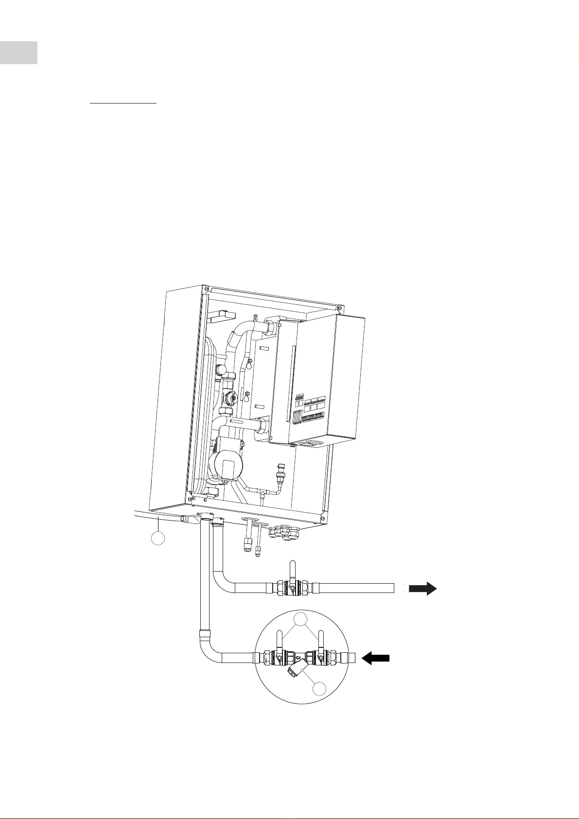
4.2 - HYDRAULIC CONNECTION
4.2.1 - WATER INLET AND OUTLET CONNECTION
• Connect the water pipes to the corresponding connections (for diameters and position, see page 6).
• It is mandatory to install a hydraulic lter (1) (not supplied) on the water intake. Connect it using two
on-off valves (2) (not supplied) for cleaning purposes.
• It is recommended to install anti-vibration exible hoses (not supplied), for the hydraulic connections.
4.2.2 - WATER FILLING / DRAINAGE CONNECTION
• Provide at the lowest point of the hydraulic circuit, outside the unit, a circuit ll / discharge tting.
4.2.3 - SAFETY VALVE CONNECTION
• The safety valve opens if the pressure of the hydraulic system exceeds 3 bar.
• A exible hose (3) (not supplied) can be connected to the condensate drain connection (connection
outside ø: 18 mm).
2
1
3
Questo manuale è adatto per i seguenti modelli
2
Indice
Altri manuali Argo Pompa di calore


Manuali Pompa di calore popolari di altre marche


Mitsubishi Electric
Mitsubishi Electric PUZ-SWM60VAA Manuale utente

Dimplex
Dimplex LI 16I-TUR Guida utente

Carrier
Carrier WSHP Open v3 Guida rapida alla configurazione

TGM
TGM CTV14CN018A Manuale utente

Carrier
Carrier 38MGQ Series Manuale utente

Kokido
Kokido K2O K880BX/EU Guida alla risoluzione dei problemi


