ARH FREEWAYCAM3 Manuale utente

FREEWAYCAM3 / SMARTCAM3 / SPEEDCAM3
DIGITAL (IP) LPR CAMERA

Page 2/17
FreewayCAM Install Guide
FREEWAYCAM3/SMARTCAM3/SPEEDCAM3 Install Guide
For versions from 3.5
Document version: 2017.11.24.
Table of Contents
Compliances......................................................................................................................................................3
1. Hardware Overview.......................................................................................................................................4
1.1 Bracket Details and Sizes........................................................................................................................4
2. Install the Hardware......................................................................................................................................6
2.1 Mounting................................................................................................................................................6
3. Connect the Cables.......................................................................................................................................7
3.1 Cable Layouts .........................................................................................................................................7
4. Software Requirements...............................................................................................................................11
5. Accessing the Camera.................................................................................................................................11
6. Recommended Camera Position.................................................................................................................12
7. Maintenance / Storage ...............................................................................................................................14
Appendix.........................................................................................................................................................15
Contact Information........................................................................................................................................17

Page 3/17
FreewayCAM Install Guide
Compliances
CE Certificates:
The ARH FreewayCAM3 ANPR digital camera family complies with the European CE requirements
specified in the EMC Directive 2014/30/EU.
The ANPR cameras conform to the following Product Specifications:
Emission and Immunity:
EN 55032:2015, EN 55024:2010+A1:2015
Declaration of RoHS Compliance for Electrical and Electronic Products:
ARH Inc. ("the Company") hereby declares that the FreewayCAM ANPR camera family placed on the
European Community market by the Company after 1st July 2006 are compliant with EC Directive
2002/95/EC on the Restrict of Certain Hazardous Substances in Electrical and Electronic Equipment
(commonly known as the EU RoHS Directive.)
Compliance with RoHS means that where the product falls under the scope of the EU RoHS Directive,
the product does not contain the following substances:
- Mercury (Hg) 0.1%
- Lead (Pb) 0.1%
- Cadmium (Cd) 0.01%
- Hexavalent Chromium (Cr+6) 0.1%
- Polybrominated Biphenyls (PBB) 0.1%
- Polybrominated Diphenyl Ethers (PBDE) 0.1%
above the indicated maximum concentration values by weight in homogeneous materials unless the
substance is subject to an exemption specified in the Directive or in subsequent Commission Decisions.
This declaration represents the Company's best knowledge, which is partially based on information
provided by third party suppliers.
Page 4/17
FreewayCAM Install Guide
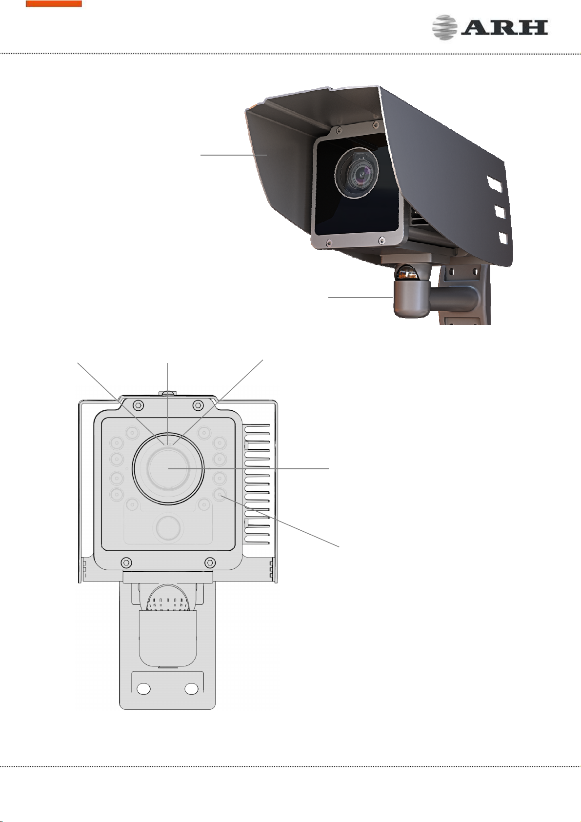
1. Hardware Overview
Sunshield
Wall bracket
Camera with bracket
Camera front
Infrared LEDs behind the
protecting plate
Camera optics
Red status LED Light sensor Green status LED
Page 5/17
FreewayCAM Install Guide
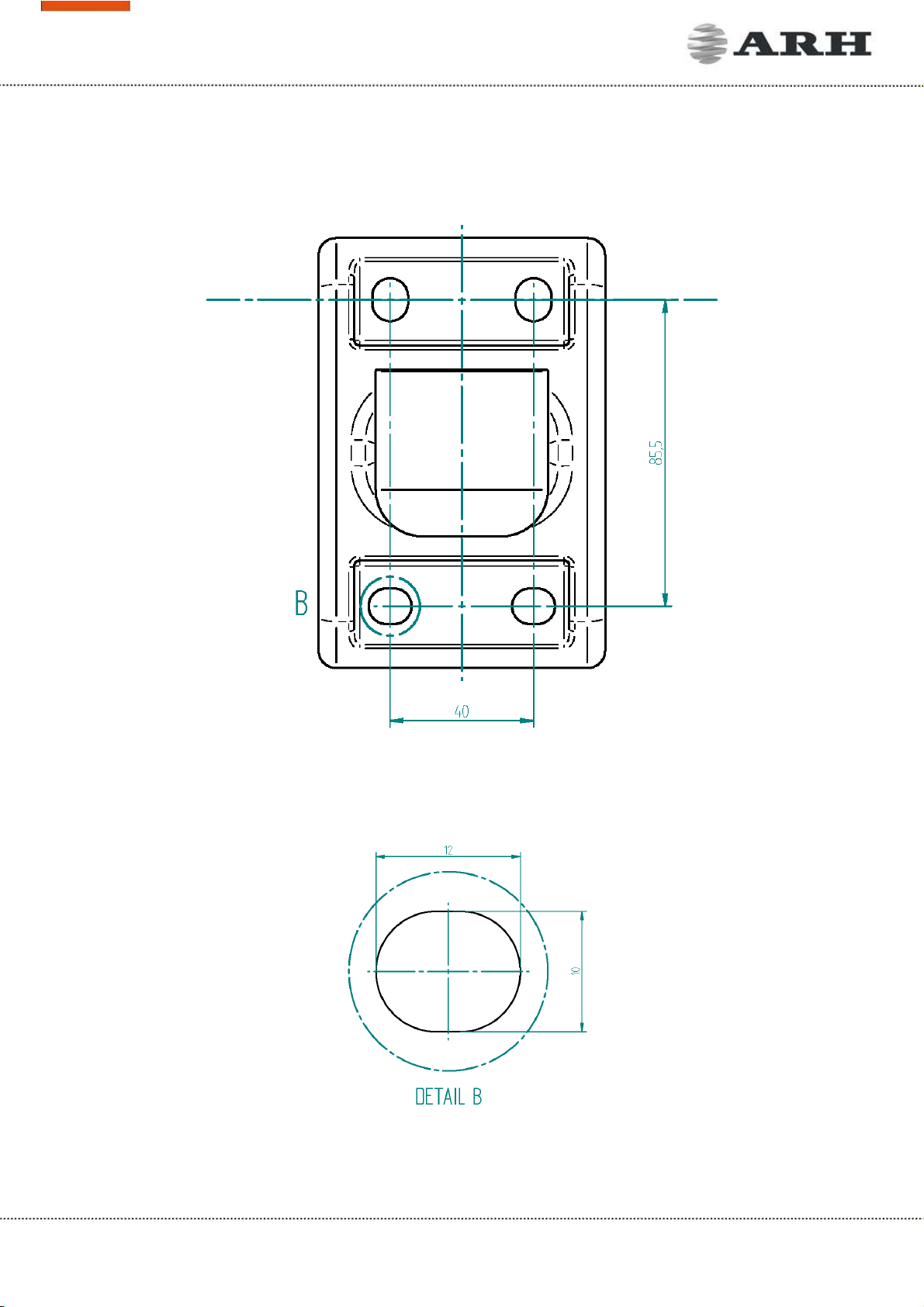
1.1 Bracket Details and Sizes
Page 6/17
FreewayCAM Install Guide
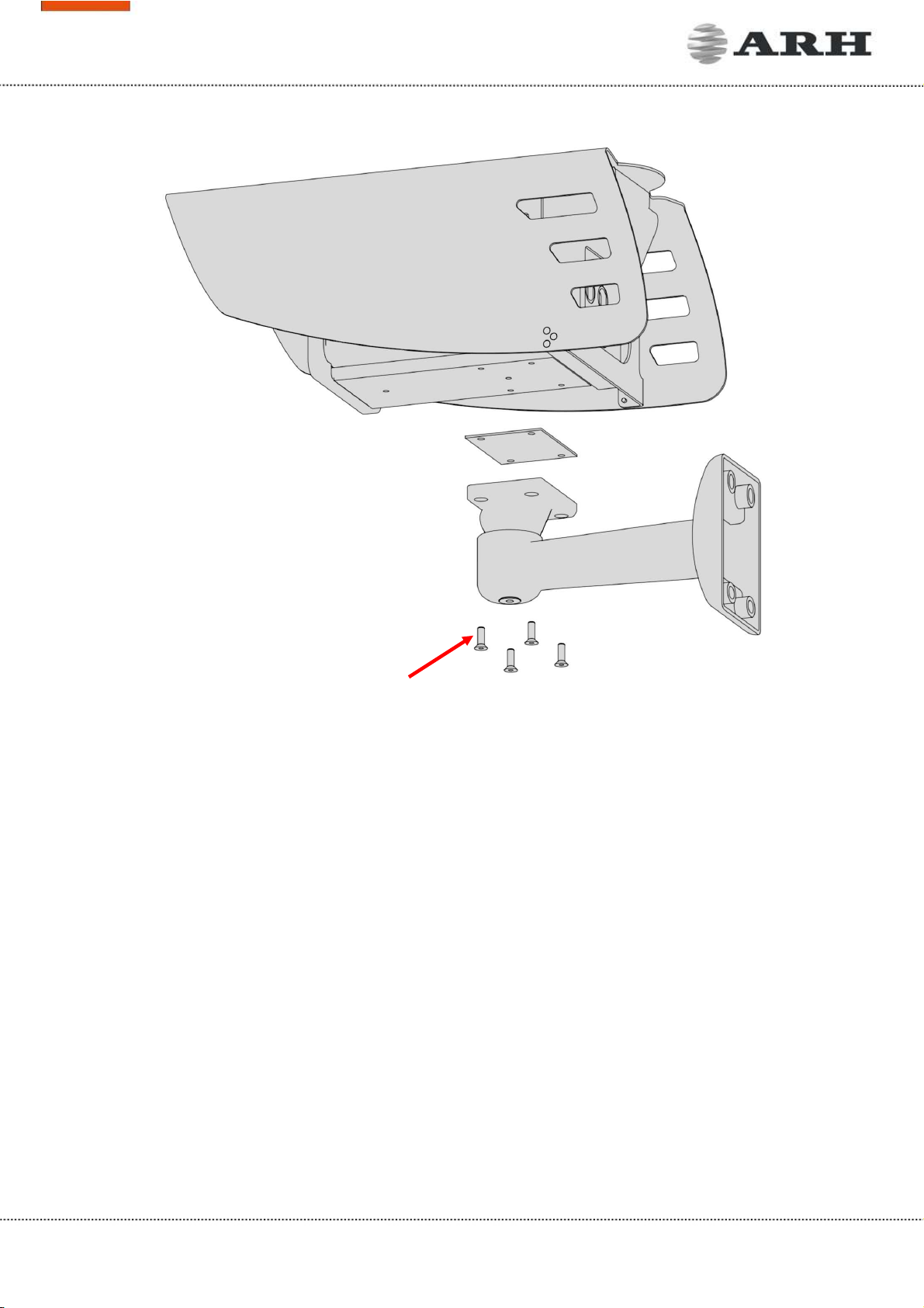
2. Install the Hardware
NOTE: Remove protective film from the protecting plate (on the camera front) before using the
camera.
Adjust the bracket
1. Loosen the camera fastening screw on the bottom of the bracket. (Use size 5 Allen key).
2. Adjust the bracket into the desired position.
3. Tighten the screw back.
NOTE: Do not overtighten the screws.
2.1 Mounting
The bracket can be mounted into different surfaces. Use appropriate screws for installation according
to the mountable surface.
NOTE: Failures due to inappropriate installation void the warranty.
Camera fastening screws
Page 7/17
FreewayCAM Install Guide
3. Connect the Cables
NOTE: Technical specifications are subject to change without prior notice.
IMPORTANT NOTICE! For cabling use quality, outdoor-certified cables! Improper cabling causes
warranty to void! Water may enter into the camera inside through loose cable ends. Use smooth
circular cables only.
SEAL THE UNUSED CABLE ENDINGS (END SLEEVES) BEFORE CONNECTING TO POWER IN ORDER TO
AVOID DAMAGES DUE TO SHORT CIRCUIT!
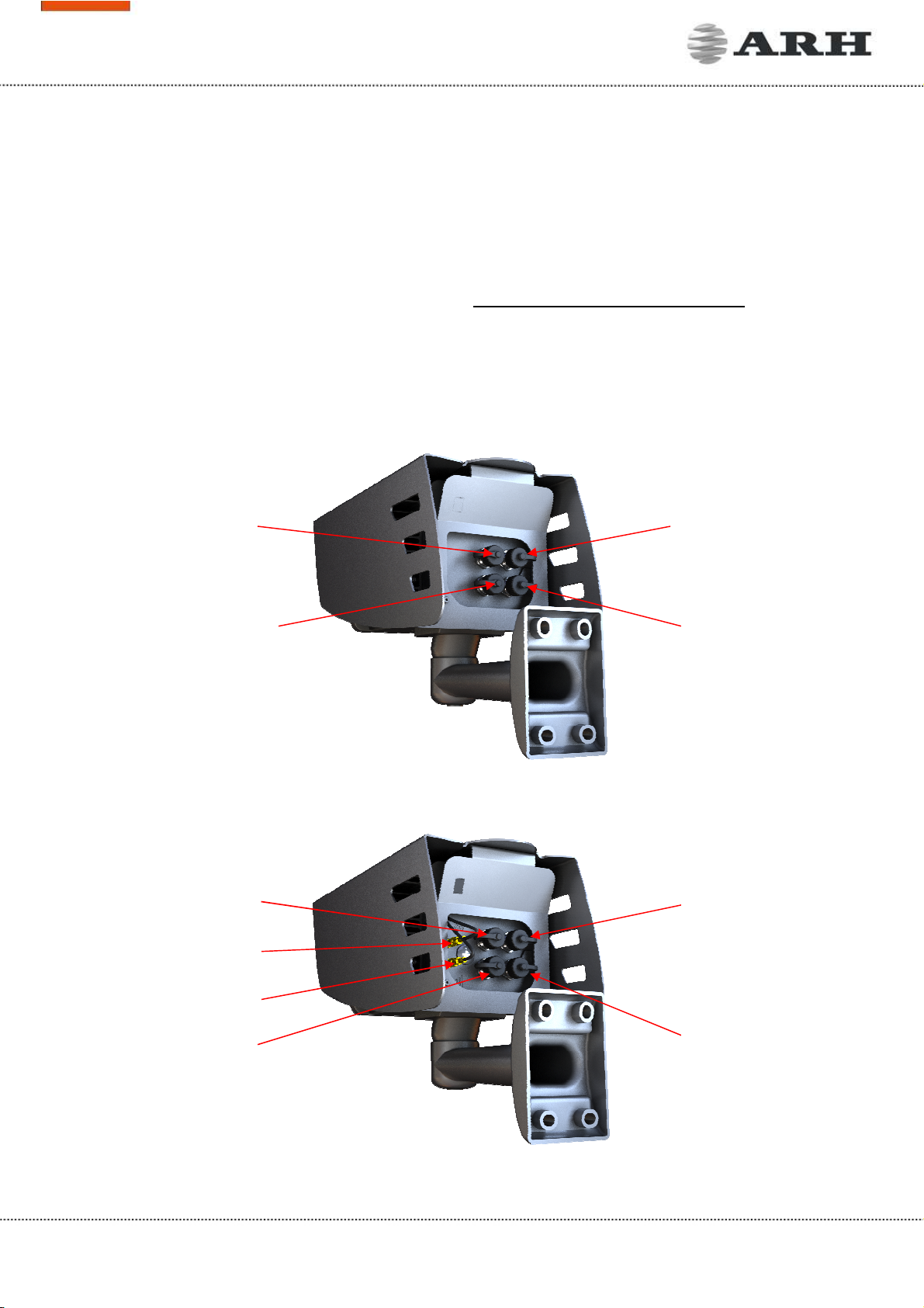
3.1 Cable Layouts
In case of cameras with four connectors:
In case of cameras with six connectors:
Ethernet
Power
I/O no.1 (12
pin)
I/O no.2 (8 pin)
Ethernet
I/O no.1 (12
pin)
I/O no.2 (8 pin)
Power
GPS
3G
Page 8/17
FreewayCAM Install Guide
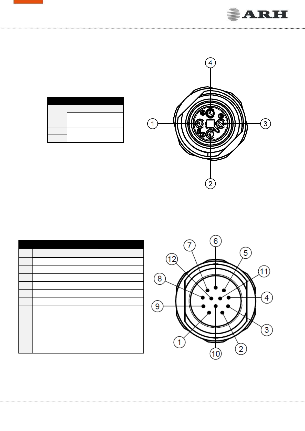
4 Pole Power Connector
Pin
Function
1 AC_1
2
3 AC_2
4
IO1: 12 Pole I/O Connector
Pin
Function Wire colour
1 OPTO_1_OUT_S
brown
2 OPTO_1_OUT_G
blue
3 OPTO_1_IN_G
white
4 OPTO_1_IN_S
green
5 ILL_STROBE
pink
6 OPTO_2_OUT_S
yellow
7 TX-ILLUM
black
8 RB_USER
grey
9 RX_ILLUM
red
10 TA_USER
purple
11 GND_ILLUM
grey/pink
12 GND_USER
red/blue
Page 9/17
FreewayCAM Install Guide
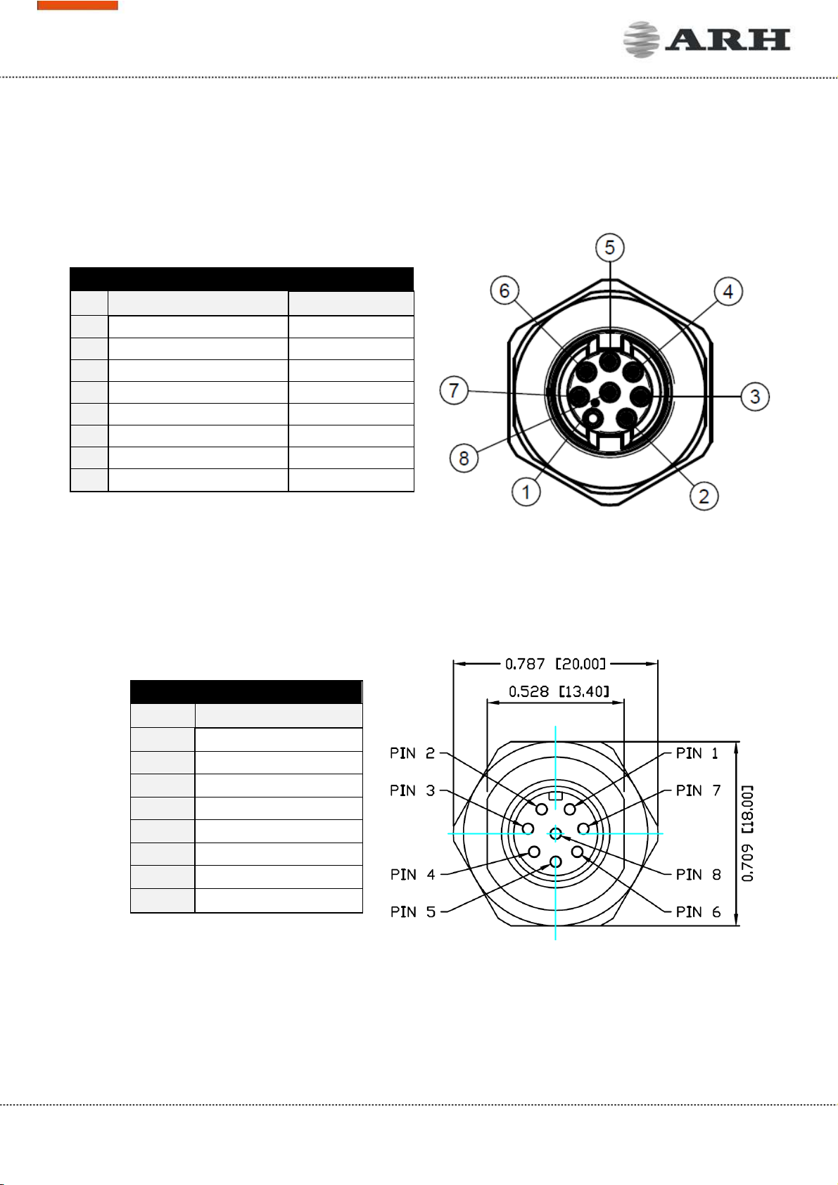
IO2: 8 Pole I/O Connector
Pin
Function Wire colour
1 RB_USER
white
2 OPTO_2_OUT_G
brown
3 TA_USER
green
4 OPTO_2_OUT_S
yellow
5 OPTO_2_IN_G
grey
6 OPTO_2_IN_S
pink
7 GND_RADAR
blue
8 12V_RADAR
red
Circular ethernet
Pin Function
1 D3-
2 D4+
3 D4-
4 D1-
5 D2+
6 D1+
7 D3+
8 D2-
Page 10/17
FreewayCAM Install Guide
POWER SPECIFICATIONS:
The required input voltage is model dependent, please use the proper input according to your
model! Please consider voltage drop if you use cables!
Camera with HD sensor Camera with FullHD sensor
AC Input isolated 24 - 28V AC (sinusoidal)
Power (typical)* 10 – 19 W 11 – 26 W
Power (max. / max. with heating) 25 / 28 W 26 / 29 W
Over-current Protection by fuse
* - Depending on usage and configuration
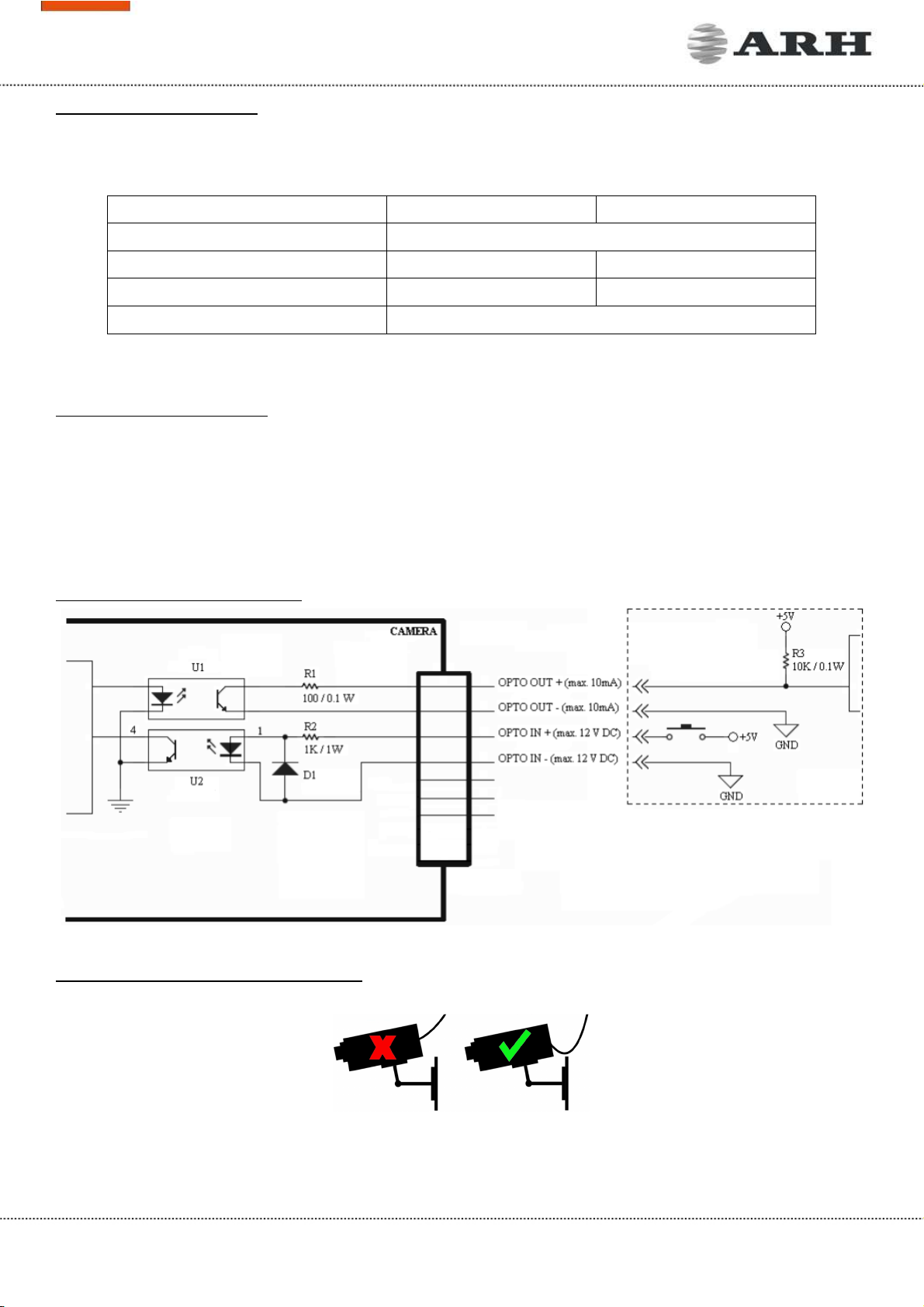
TRIGGER SPECIFICATIONS:
•Input: min. 5V, max. 12V Logic Output: min. 5V, max. 12V, max. 10mA
•Pulse width: min. 1 ms
NOTE: Be aware of the polarity.
SCHEMATIC FOR TRIGGERING:
SERIAL CONNECTION SPECIFICATION:
The serial port of the camera complies with the RS 232/485 standard.
Route the cable according to the image
to avoid collecting rainwater at the socket.
EXTERNAL WIRING SCHEMATIC
Altri manuali per FREEWAYCAM3
2
Questo manuale è adatto per i seguenti modelli
2
Indice
Altri manuali ARH Macchina fotografica digitale


