ArrowVision Shepherd 210 Manuale utente

Shepherd 210
Fingerprint Door Lock
Installation Manual
V3.1

DL210 Installation Manual V3.1
1
Table of Contents
1. Product and Accessories …………………………………………………..2
1.1 Parts List……………………………………………………………….2
1.2 Parts Identification…………………………………………………......3
2. Installation………………………………………………………………….5
2.1 Preparation before Installation…………………………………………5
2.2 Drill Holes……………………………………………………………...6
2.3 Adjust Latch’s Backset………………………………………………....6
2.4 Adjust Deadbolt’s Backset……………………………………………...7
3 Install Latch, Deadbolt and Strikes ………………………………………...9
3.1 Install Latch and Deadbolt ……………………………………………..9
3.2 Install Strikes and Lining Boxes………………………………………10
4 Install the Lock Units………………………………………………………11
4.1 Adjust Torque Bar Length…………………………………………......11
4.2 Install Outside Unit…………………………………………………....11
4.3 Install Inside Unit……………………………………………………...12
4.4 Check and Adjust after Installation…………………………………....13
5 Problems or Feedback……………………………………………………..13

DL210 Installation Manual V3.1
2
1. Product and Accessories
1.1 Parts List
After opening the package, please check the product and accessories. If any are
missing or damaged, please contact your dealer for replacement.
Inside unit Outside unit Pinch screws
Deadbolt Deadbolt strike Deadbolt strike lining box
Latch Latch strike Latch strikelining box
Square axis for latch Wood screw Emergency keys
DL210 Installation Manual V3.1
3
The Manual Cutout template
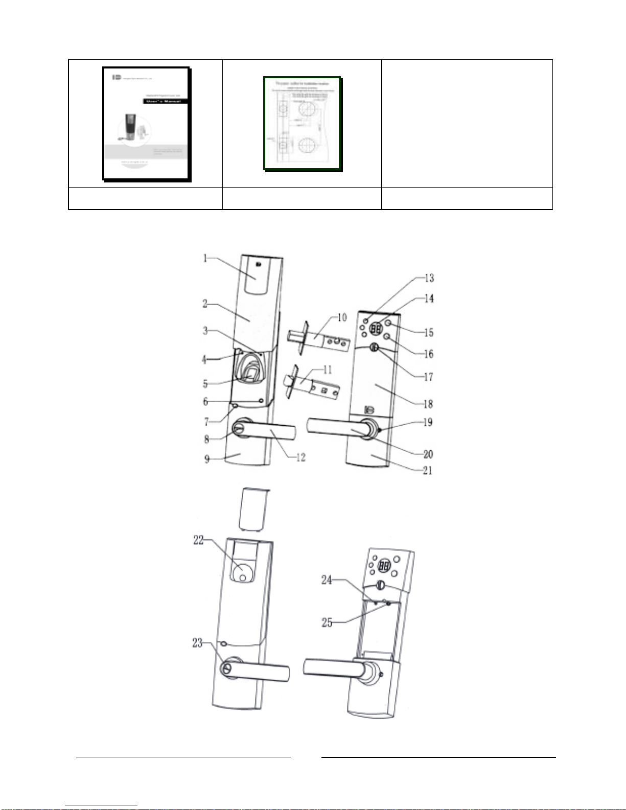
1.2 Parts Identification

DL210 Installation Manual V3.1
4
1. Decoration plate 14. LED display
2. Sliding dust cover 15. Inside unlocking button
3. Green LED indicator 16. Inside locking button
4. Red LED indicator 17. Battery compartment knob
5. Fingerprint scanning window 18. Battery compartment
6. Power on switch 19. Pinch screw holes
7. Outside locking button 20. Inside lever
8. Emergency keyhole cover 21. Inside unit body
9. Outside unit body 22. Deadbolt keyhole
10. Deadbolt 23. Latch emergency keyhole
11.Latch 24. Deadbolt emergency release hole
12.Outside lever 25. Pinch screw hole
13.Function keys
DL210 Installation Manual V3.1
5
2. Installation
2.1 Preparation before Installation
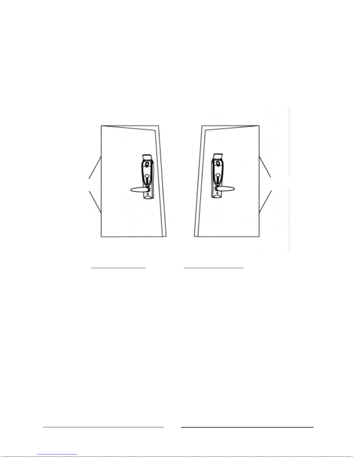
Your lock must correspond to your door being left-handed or right-handed. If
not, you should ask your seller to exchange it. (Refer to Figure1)
Left-Hand Door Right-Hand Door
Fig 1: Viewing from the outside; definition of doors
¤Tip: How to determine the door opening direction?
Standing outdoor and face the door: If the hinge is at the left side of the
door, the door is a left-handed door -the left-handed lock should be used. If
the hinge is at the right side of the door, the door is a right-handed door -
the right-handed lock should be used.
The lock lever is designed to be interchangeable with the popular Schlage or
Kwikset standard for 2 lock hole doors. If your door has only one hole or no
holes in the door, follow the instructions below. (Note: Most hardware stores
have 2-1/8” and 1” hole cutters that fit standard hand drills.)
Hinge
Hinge
DL210 Installation Manual V3.1
6
2.2 Drill Holes
(1) Paste the provided cutout template on the door as shown in the figure. Mark
1” holes at center of door edge and make 2” holes at the surface of the door (the
offset is 2 3/8” or 2 3/4” from door edge to the center of the 2” hole).
(2) Drill two 1” holes on door edge. And drill two 2” holes on the door surface.
%Hint: To avoid cracking the door surface, the 2” holes should be drilled from
both sides.
(3) There are adjustable backsets for the latch and deadbolt. Set them to either 2
3/8” or 2 3/4” as appropriate for your door.
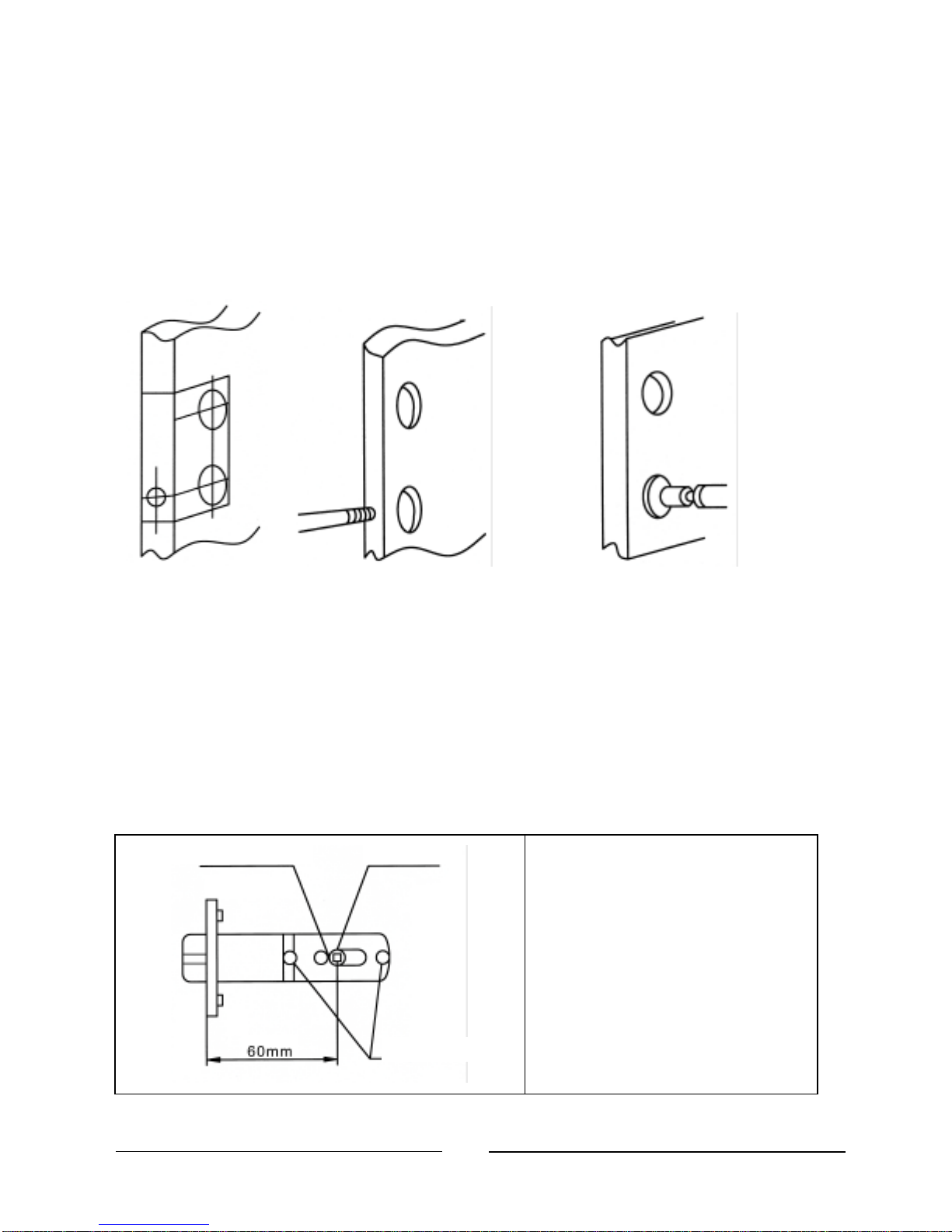
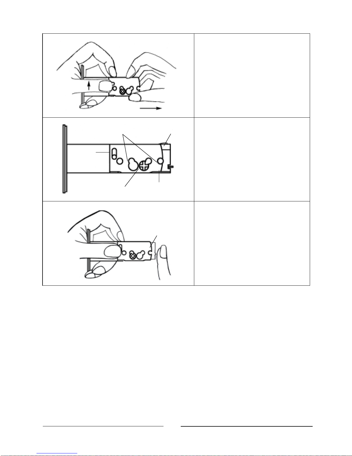
2.3 Adjust Latch’s Backset
The backset is at the 2 3/8”
position, when the product
is shipped from the factory.
The left of
adjustment
hole
Regulator
pin
Screw
-
post hole
DL210 Installation Manual V3.1
7
Pull regulator pin to the right
edge.
The backset has been
adjusted to 2 3/4” position.
Make sure the regulator
pin is at the correct angle
as shown.
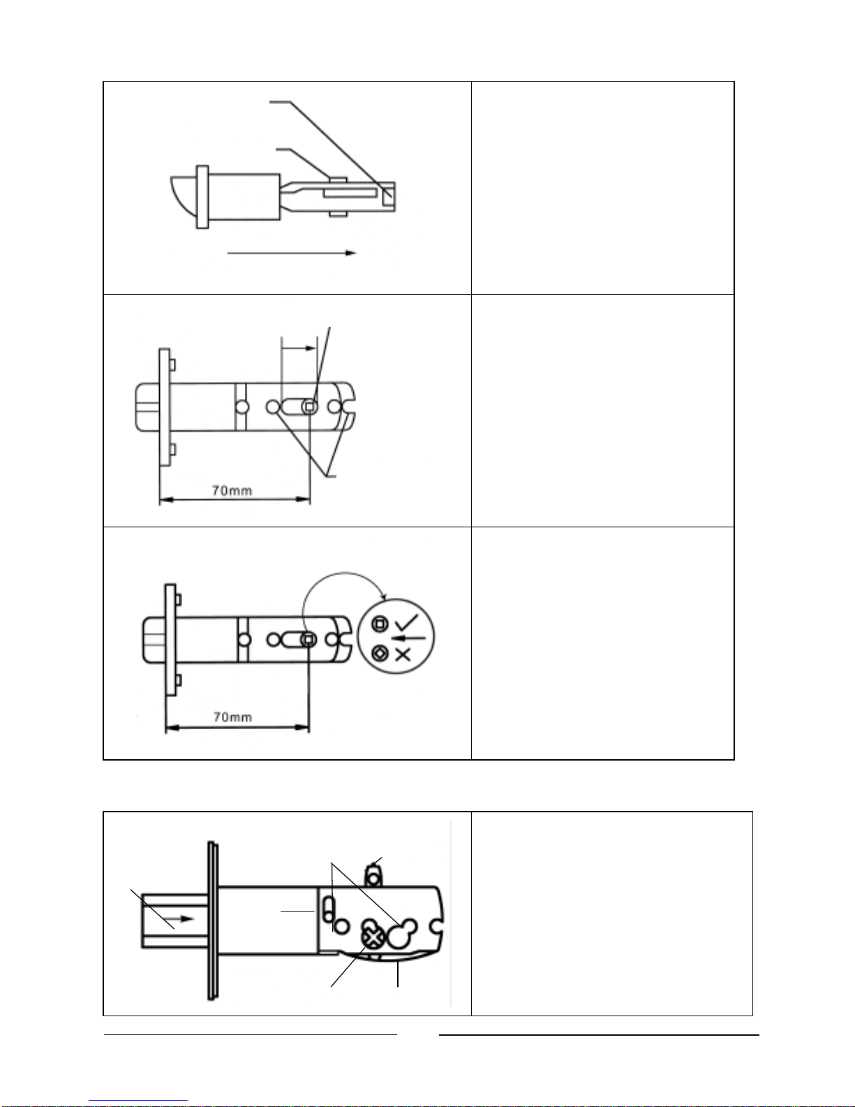
2.4 Adjust the Deadbolt’s Backset
Insert a flat screwdriver into
driving board hole, turn driving
board to let the deadbolt head
draw in.
2 ¾”
Pinch
Screw Holes
Driving
Board
Driving
spring
Driving
Board Hole
Deadbolt
Head
Regulator
Pin
The clip of regulator pin
Regulator
pin
Pull
The right edge of
adjust
hole
Screw
-
post hole
DL210 Installation Manual V3.1
8
Pull regulator pin up, firmly
hold driving board and driving
spring and pull right until the 2
3/4” screw hole coincides with
driving board hole.
Figure shows the backset is in
2 3/4” position.
If you would like to return to
the 2 3/8” backset, make sure
deadbolt is drawn in. Pull
regulator pin up, push back
convex stretcher to its original
position.
2 ¾” Pinch
Screw Holes
Driving
Board
Regul
ator
Pin
Driving
Board Hole
Driving
spring
Stretcher Board
DL210 Installation Manual V3.1
9
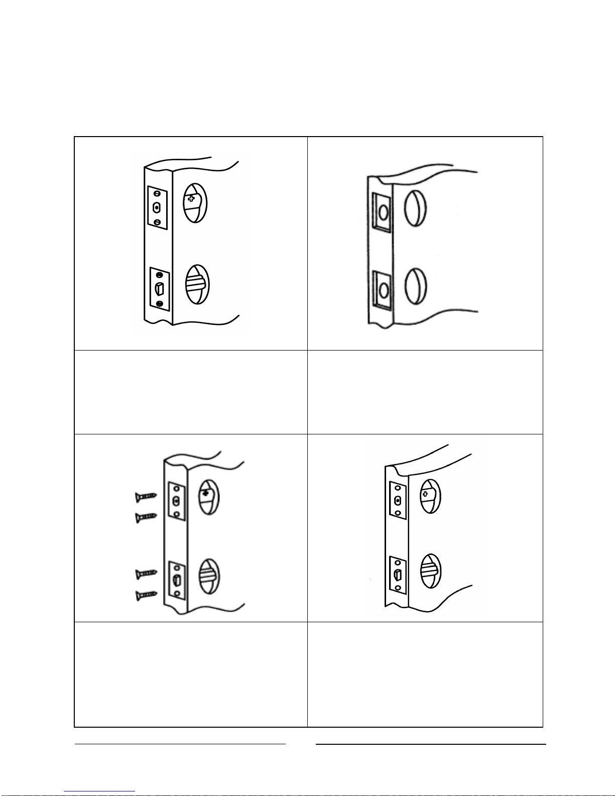
3Install Latch,Deadbolt and Strikes
3.1 Install Latch and Deadbolt
Insert the lock bolt into the hole,
mark the frame lines of foil board.
The frame lines should be parallel
with the door edge.
Dig a support notch 1/8” in depth.
The notch edge lines should be
parallel with the door edge.
Insert latch and deadbolt, and tighten
the screws (the slanted plane of latch
should face the door closing
direction, and the UP mark of the
deadbolt should point down).
After the screws are tightened, the
foil board should be exactly in the
door center and parallel with door
edge.
Altri manuali per Shepherd 210
1
Indice
Altri manuali ArrowVision Serratura della porta


