ASEA AC25Q-1 Manuale utente

Operations Manual
for the ASEA Power Systems
Model AC25Q-1, AC25Q-3, AC30Q-1, and AC30Q-3
Single and Three Phase Yacht Power Converters
P/N 607055
Revision B
Issued 2/17/12

AC25/30Q-1 and -3 Operations Manual....2
CERTIFICATION
ASEA Power Systems certifies that this product was thoroughly tested and inspected and
found to meet or exceed its published specifications when shipped from the factory.
WARRANTY
ASEA Power Systems warrants each unit to be free from defects in material and
workmanship. For a period of 18 months after purchase or 12 months after installation
(whichever is shorter), ASEA Power Systems will repair or replace any defective module
provided the unit has been installed and operated in a manner according to this manual. A
thorough inventory of spare parts & modules is maintained at our factory. Our world-wide
sales/support facilities also inventory a complement of spare parts and modules.
ASEA Power Systems is not responsible for consequential damage arising from the use of
its equipment. It does not apply to extensively modified or non-standard systems. Debit
memos for returned units are not accepted, and will cause return of the system without
repair.
LIFE SUPPORT POLICY
ASEA Power Systems does not authorize the use of any of its products or systems for use
an AC voltage supply (source) for life support systems. Life support systems are devices
which support or sustain life, and whose failure to perform, when properly used in
accordance with this Operations Manual, can be reasonably expected to result in
significant injury to the user.

AC25/30Q-1 and -3 Operations Manual....3
1 USING THIS MANUAL
This manual has been written as an Operations Manual. Installation, operations, and
preventative maintenance are covered in detail. This manual will cover the following
models:
AC25Q-1 25kVA 1 Phase Yacht Power Converter
AC25Q-3 25kVA 3 Phase Yacht Power Converter
AC30Q-1 30kVA 1 Phase Yacht Power Converter
AC30Q-3 30kVA 3 Phase Yacht Power Converter
Each converter is capable of being paralleled for higher power applications.
The Model AC25Q can be paralleled to produce the following models:
AC50Q-1/2 50kVA 1 Phase Yacht Power Converter
AC50Q-3/2 50kVA 3 Phase Yacht Power Converter
The Model AC30Q can be paralleled to produce the following models:
AC60Q-1/2 60kVA 1 Phase Yacht Power Converter
AC60Q-3/2 60kVA 3 Phase Yacht Power Converter
It is important that the operator reads this manual prior to installing and operating the
converter. A thorough understanding of the information covered in this manual is required
for proper installation and operation.
If any questions arise while reading this manual, the user is encouraged to call ASEA
Power Systems. ASEA Power Systems is located at:
ASEA Power Systems
15602 Commerce Lane
Huntington Beach, CA. 92649
Phone (714) 896-9695
FAX (714) 896-9679
Web http://www.aseapower.com

AC25/30Q-1 and -3 Operations Manual....4
TABLE OF CONTENTS
CERTIFICATION ...........................................................................................................................2
WARRANTY ..................................................................................................................................2
1 USING THIS MANUAL.....................................................................................................3
2 SAFETY NOTICES.............................................................................................................6
3 INTRODUCTION TO THE AC25Q AND AC30Q............................................................8
4 SPECIFICATIONS............................................................................................................10
4.1 ELECTRICAL SPECIFICATIONS ......................................................................10
4.1.1 Input Service..............................................................................................10
4.1.2 Output Service ...........................................................................................10
4.1.3 Control, Metering, and Status....................................................................12
4.2 PHYSICAL SPECIFICATIONS...........................................................................12
4.2.1 Mechanical ............................................................................................12
4.2.2 Environmental............................................................................................12
5 INSTALLATION ..............................................................................................................13
5.1 MECHANICAL INSTALLATION.......................................................................14
5.2 ELECTRICAL INSTALLATION.........................................................................18
5.2.1 Input Power Connections...........................................................................20
5.2.2 Output Power Connections........................................................................20
5.2.3 Grounding..................................................................................................22
5.2.4 Multi-Cabinet Connections........................................................................23
5.2.5 Seamless Transfer Connections.................................................................24
5.2.6 Other Optional Connections ......................................................................25
6 OPERATION.....................................................................................................................26
6.1 POWER TURN-ON PROCEDURE......................................................................26
6.1.1 Systems Not Equipped With The Seamless Transfer Option....................28
6.1.2 Systems Equipped With The Seamless Transfer Option...........................29
6.2 MULTI-CABINET TURN-ON PROCEDURE ....................................................31
6.3 AUTO-RESTART FEATURE ..............................................................................32
6.3.1 Operation....................................................................................................33
6.4 TURN-OFF PROCEDURE...................................................................................34
6.4.1 Systems Not Equipped With The Seamless Transfer Option....................34
6.4.2 Systems Equipped With The Seamless Transfer Option...........................35
6.5 REMOTE COMMUNICATION...........................................................................36
6.5.1 RS-232C/SCPI...........................................................................................37
6.5.2 RS-485/Modbus.........................................................................................38

AC25/30Q-1 and -3 Operations Manual....5
7 SOFTWARE FEATURES.....................................................................................39
7.1 GENERAL.............................................................................................................39
7.2 LOAD MANAGEMENT.......................................................................................39
7.3 LOAD MANAGEMENT OPERATION...............................................................41
7.3.1 Shore Cord Alarm, Single, Master, and Slave Converters ........................41
7.3.2 Shore Cord Setup, Single, Master, and Slave Converters..........................42
7.3.3 Voltage Droop, Single or Master Converters ............................................43
7.3.4 Automatic Transfer to Generator, Single or Master Converters................44
7.3.5 Quick Setup of Shore Cord Alarm, Single, Master, and Slave Converters45
7.4 GENERATOR FREQUENCY ANALYSIS..........................................................46
7.5 CONVERTER OUTPUT IMPEDANCE CONTROL...........................................46
7.6 AGC CONTROL...................................................................................................47
7.7 kW-HOUR METER AND MAX POWER LEVEL DISPLAY............................48
7.8 CONVERTER OUTPUT VOLTAGE CONTROL...............................................49
7.9 EVENT LOG.........................................................................................................50
8 TROUBLE-SHOOTING AND DIAGNOSTICS..............................................................52
8.1 COMMON PROBLEMS.......................................................................................52
8.2 FAILURE AND WARNING MESSAGES...........................................................53
8.3 INFO DISPLAY ....................................................................................................53
8.4 STATUS WORDS.................................................................................................54
8.5 GATHERING DATA............................................................................................54
8.6 SOFTWARE TOOLS............................................................................................54
9 CALIBRATION ................................................................................................................56
10 MAINTENANCE..............................................................................................................58
11 INTERNATIONAL POWER FORM REFERENCE........................................................59
12 INDEX...............................................................................................................................66
FIGURES
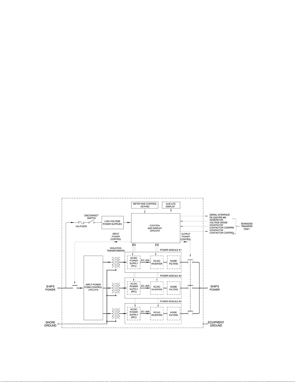
1 SYSTEM BLOCK DIAGRAM...............................................................................8
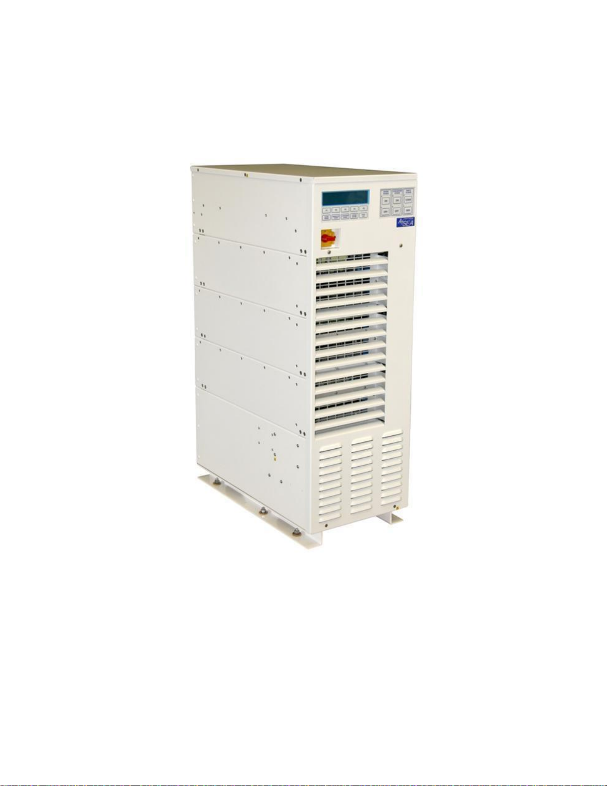
2 MECHANICAL OUTLINE...................................................................................16
3 CONTROLS ..........................................................................................................17
4 INPUT AND OUTPUT CONNECTIONS............................................................21
5 CONTROL MODULE CIRCUIT BOARDS ........................................................23
6 FRONT PANEL CONTROLS ..............................................................................26
7 RS-232C PINOUT.................................................................................................37
8 RS-485 CONNECTIONS......................................................................................38
9 STATUS WORD BIT DEFINITIONS..................................................................55

AC25/30Q-1 and -3 Operations Manual....6
2 SAFETY NOTICES
Each shore power converter is capable of transferring very large amounts of electrical energy
very quickly. This quality is fundamental to a high performance power converter. International
symbols are used throughout this manual to stress important information. Read the text below
each symbol carefully and use professional skills and prudent care when performing the actions
described by the text.
THE CAUTION SYMBOL (TRIANGLE ENCLOSING AN EXCLAMATION
POINT) INDICATES A CONDITION THAT COULD SERIOUSLY DAMAGE
EQUIPMENT AND POSSIBLY INJURE PERSONNEL. CAUTIONS WILL BE
PRESENTED IN THIS FORM. ALL CAUTIONS SHOULD BE RIGOROUSLY
OBSERVED.
THE WARNING SYMBOL (TRIANGLE WITH A LIGHTNING BOLT) IS USED
TO SIGNAL THE PRESENCE OF A POSSIBLE SERIOUS, LIFE
THREATENING CONDITION. A CONDITION THAT IS HAZARDOUS TO
BOTH PERSONNEL AND EQUIPMENT WILL BE ISSUED AS A WARNING.
ALL WARNINGS WILL BE PRESENTED IN THIS FORM.

AC25/30Q-1 and -3 Operations Manual....7
THIS EQUIPMENT CONTAINS HIGH ENERGY, LOW IMPEDANCE
CIRCUITS! LETHAL POTENTIALS ARE CONTAINED WITHIN THE
SYSTEM—EVEN WHEN IT IS APPEARS TO BE NON-OPERATIONAL.
CARE MUST BE EXERCISED WHEN SERVICING THIS EQUIPMENT IN
ORDER TO PREVENT SERIOUS OPERATOR INJURY OR EQUIPMENT
DAMAGE.
DO NOT WORK ON OR OPERATE THIS EQUIPMENT UNLESS YOU ARE
FULLY QUALIFIED TO DO SO. NEVER WORK ALONE.
THE EQUIPMENT IS NOT IGNITION RATED, IT MUST NOT BE OPERATED
IN AREAS WHERE COMBUSTIBLE GASES MAY ACCUMULATE.
DO NOT REMOVE THE SHORE CORD FROM THE DOCK PEDESTAL
WITHOUT FIRST OPENING THE DOCK OR YACHT BREAKER. FAILURE
TO DO SO MAY RESULT IN DAMAGE TO THE CONVERTER AND
PEDESTAL.
OBSERVE THE FOLLOWING WHEN SERVICE AND MAINTENANCE ARE
REQUIRED:
REMOVE ALL JEWELRY FROM ARMS AND NECK WHEN SERVICING
THIS EQUIPMENT. THIS PREVENTS THE POSSIBILITY OF SHORTING
THROUGH THE JEWELRY, OR ELECTROCUTION OF THE OPERATOR.
WEAR SAFETY GLASSES WHEN SERVICING THIS EQUIPMENT TO
PREVENT EYE INJURY DUE TO FLYING PARTICLES CAUSED BY
ACCIDENTAL SHORT CIRCUIT CONDITIONS.
DO NOT REMOVE ANY PANELS OR COVERS WITHOUT FIRST
OPENING ALL SHORE POWER AND SWITCHGEAR CIRCUIT
BREAKERS DISTRIBUTING POWER TO AND FROM THE CONVERTER,
AND THEN REMOVING THE INPUT SERVICE.
SERVICE SHOULD BE REFERRED TO PERSONNEL AUTHORIZED BY
THE FACTORY TO SERVICE THIS EQUIPMENT.

AC25/30Q-1 and -3 Operations Manual....8
3 INTRODUCTION TO THE AC25Q AND AC30Q
Each model is a high performance Yacht Power Converter utilizing dual-conversion technology.
The systems will accept any single or three phase input service with a frequency between 40-70
Hertz, and a voltage between 170-520VAC. Input service may consist of one single phase or one
three phase shore voltage; the converter will auto-configure for the applied power form.
The output power form has been programmed at the factory for the power form (single or three
phase), voltage and frequency, required by your yacht.
Dual-conversion technology is the preferred technique for AC power conversion, and was
chosen for these systems. In this technology, the shore power service is isolated by transformers
then converted to DC power by the Power Factor Correction (PFC) power supplies. The output
inverters then convert the DC power back to the required AC form (both voltage and frequency)
required by the yacht.
FIGURE 1 BLOCK DIAGRAM

AC25/30Q-1 and -3 Operations Manual....9
3 INTRODUCTION TO THE AC25Q AND AC30Q, cont.
Being a converter designed from the ground up specifically for the yachting industry, all efforts
have been made to produce a system capable of withstanding the marine environment. The
system is constructed using a modular approach where the converter consists of a control module
(upper), three power modules (middle), and a transformer module (bottom). This allows the
converter to be broken down into five parts to facilitate its movement into a vessel through
existing personnel entry points. All system components are packaged in drip-proof, dust-
resistant, aluminum chassis. Major components are internally modular, allowing a simple
exchange in the unlikely event of failure. Maintenance and service are performed through top
access to the upper control module, exchange of power modules, and front/top access to the
transformer module.
Fan speed control is provided. Internal cooling fans will run at full rpm when the converter is at
full load, and minimal speed while unloaded.
System operation is managed through two basic operators:
A safety disconnect on the front of the enclosure is used for securing input service during periods
of disuse, when maintenance and/or service is in-process, or when an emergency shutdown is
needed.
Three membrane switch groups in the control console—SHORE POWER, CONVERTER
POWER, and SHIP’S POWER—provide normal operation of the system. Each switch group
contains an ON and OFF switch with associated LED indicators.
In addition to the basic function of power conversion, each system provides the user with a
sophisticated power analysis and monitoring capacity. All parameters for input and output
power, along with operations and status information, are available on the front panel display
console. Various displays are selected through a long life, sealed membrane switch panel.
For additional information on controls and indicators, please refer to Section 6.

AC25/30Q-1 and -3 Operations Manual....10
4 SPECIFICATIONS
4.1 ELECTRICAL SPECIFICATIONS
Parameter AC25-1, -3 AC30-1, -3
4.1.1 Input Service
Input Power Form Single or Three Phase Single or Three Phase
Input Voltage Range 170-520 VAC 170-520 VAC
Input Frequency Range 40-70 Hertz 40-70 Hertz
Input Current, Max. Single Phase 105 ARMS 125 ARMS
or, Max. Three Phase 70 ARMS 83A
RMS
Input Current, Soft Start, Max. 20 ARMS 20A
RMS
Input Current Distortion <5% THD @ rated load <5% THD @ rated load
Input Power Factor >0.99 @ rated load >0.99 @ rated load
4.1.2 Output Service
Output Power Rating 25kVA @ 0.85 p.f. 30kVA @ 0.85 p.f.
Output Power Form Single Phase 220 or 230 VRMS, Split Phase 120/240 VRMS
or, Three Phase 120/208, 127/220, 220/380, 230/400, or 240/416
*Note: Minor variations in the above voltage levels can be accommodated, contact
factory for additional information.
Output Frequency 50 or 60 Hertz 50 or 60 Hertz
Output Frequency Accuracy 0.01% 0.01%
Output Voltage Distortion < 1.5% THD < 1.5% THD
Output Voltage Line Regulation 0.50% 0.50%
Output Voltage Load Regulation 1.0% 1.0%
Output Voltage Response Time 0.20 msec. 0.20 msec.
Output Current, Continuous Refer to Table 1 on the following page for basic ratings.
Output Current, Peak 400% of cont. rating 400% of cont. rating
Output Current, Surge 250% of cont. rating 250% of cont. rating
Conversion Efficiency 89% @ rated load 89% @ rated load
Questo manuale è adatto per i seguenti modelli
3
Indice
Altri manuali ASEA Convertitore multimediale

ASEA
ASEA AC36NVHE-3 Manuale utente

ASEA
ASEA AC100Q-3 Manuale utente

ASEA
ASEA AC08 Manuale utente

ASEA
ASEA AC55LC-3 Manuale utente

ASEA
ASEA AC25V Manuale utente

ASEA
ASEA AC55V-3 Manuale utente

ASEA
ASEA AC50Q-3 Manuale utente

ASEA
ASEA AC15QTP Manuale utente

ASEA
ASEA AC36V-1 Manuale utente

ASEA
ASEA AC24 Manuale utente


