ASHAPOWER NEON-40 Manuale utente
1
NEON -40(HV)
Vers.3.3
MULTI VOLTAGE RANGE
SOLAR MPPT CHARGE CONTROLLER
USER MANUAL
MULTI VOLTAGE RANGE
SOLAR MPPT CHARGE CONTROLLER
1
NEON -40 SOLAR MPPT CHARGE CONTROLLER
SALIENT FEATURES
ASHAPOWER® NEON-40HV Solar MPPT Charge Controllers
are multi voltage range devices that are unique in its kind in the
market. The same device can be used for battery banks ranging
from 1 Battery(12V) up to a battery bank of 4 batteries (48V) in
series. The battery voltage is selected by the device itself when
we connect the battery bank across its terminal. The device gives
a configurable charging current up to 40A.The Max PV panel input
open circuit voltage up to 185V makes it easier to group the
panels conveniently. Also, sleek & stylish design of the product
gives a better aesthetic view so that you can wall mount the
product in a visible place inside your home or office.
● Compable for 12/24/36/48V Battery Bank
● Auto-Detection and setting of Battery Bank.
● Smart charging for prolonged battery life.
● Ultra-fast & efficient (98.9%) power point tracking.
● PV panel reverse polarity protecon.
● Automac disconnecon of PV panels at night.
● Over voltage protecon from PV panel.
● Protecon for baery against hardware failures.
● Over charging & overload protecon.
2
NEON 40 SPECIFICATIONS
Max PV Array Open Circuit Voltage (Voc) 185V
Max PV Array Watts Applicable 2000W
Nominal Battery Voltage 12/24/36/48 V
(Auto Setting)
Maximum Charging Current 40A (Configurable)
Maximum Tracking Efficiency 98.9%
Standby Power Consumption <1.5W
Overload Protection ✔
Over Charge Protection ✔
Panel Reverse Polarity Protection ✔
Battery Reverse Polarity Protection Optional
Dimensions – L x W x H (mm) 318x215x112
Net Weight (Kgs) 3.6Kgs
Connector Input / Output Terminal
Block
Communication Display/UART
3
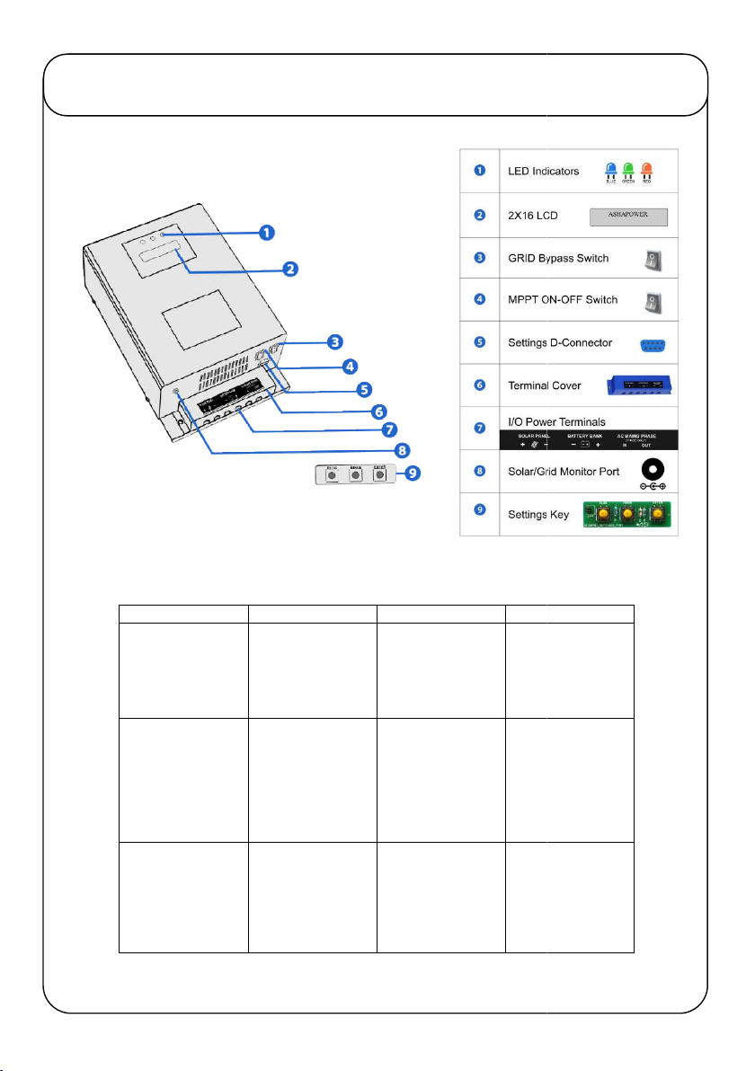
KNOW YOUR DEVICE
INDICATOR
ON
OFF
BLINKING
BLUE
SOLAR/GRID
POWER STATUS
LOAD IS ON
SOLAR POWER
LOAD IS ON GRID
POWER
BATTERY LOW
WARNING TO
AVOID
GREEN
SOLAR OUTPUT
STATUS
PV PANEL
VOLTAGE IS
HIGHER THAN
BATTERY BANK
VOLTAGE
PV PANEL
VOLTAGE IS
LOWER THAN
BATTERY BANK
VOLTAGE / OR NO
PV PANEL
CONNECTED
BATTERY
CHARGING AND
SHARING TO
CONNECTED
RED
SOLAR CHARGING
STATUS
SOLAR CHARGING
CURRENT IS
DETECTED MORE
THAN 2 AMPS.
CHARGING
STARTS
SOLAR CHARGING
CURRENT IS LESS
THAN 2 AMPS.
CHARGING STOPS
BLINKING
BATTERY LOW
WARNING TO
AVOID
HEAVY
LOADS
BATTERY
CHARGING AND
SHARING TO
CONNECTED
LOAD
-

4
1.PV Panel Grouping
:
Using required Solar MC4 connectors and parallel connectors,
group the PV panel array according to the recommended grouping chart provided.
Good quality weather proof solar cables must be used.
2.Battery Bank Setup
:
If more than one battery is used, Connect the interlinking
cables (16 sq.mm minimum) tightly and check each battery separately for specific
gravity and backup.
3.MPPT Charge Controller Installation:
-
- Mount the MPPT charge controller vertically on the wall.
- Never keep any object on the device blocking the cooling fan.
- Avoid exposure to rain, direct sunlight or high temperature.
- Remove the terminal cover of the device and make sure the device is switched off.
- Connect the device to the battery bank using 16sq.mm/10Sq.mm standard cables.
- Connect the cables from PV panels to the solar terminals of the device with correct polarity.
- Switch ON the Power switch of the device.
-Three LED Indicators and cooling fan of the device starts functioning for 5 seconds and goes
off.Display shows the voltage of the connected battery bank and applicable range of PV
Panel Open Circuit Voltage (Voc) limit for the connected battery bank.Ensure the displayed
battery bank voltage and connected battery bank voltage are same when MPPT is powered
ON.
The Charger starts functioning when the PV Panel voltage detected is higher than
the connected battery bank voltage and green LED lights up. If the PV panel voltage
goes below the battery bank voltage the green indicator goes off. When the device
detects more than 2A charging current to the battery, RED LED lights up. If the
current is less than 2A the RED LED goes off. When the battery voltage reaches
14.0V(Configurable) the BLUE LED lights up and the phase input to the inverter
connected through the MPPT will be blocked. Now the load starts functioning on
inverter (Solar). When the solar charging current stops the load will be taken from
the battery bank and the battery voltage goes down. Once it reaches
11.0V(Configurable) the device change over the load from inverter to grid power and
the blue LED goes off. Blinking blue LED indicates Low battery bank voltageie.11.7V
(Configurable)giving warning to remove heavy loads.The blinking of green LED
indicates sharing of solar current for battery charging and connected load. Solar/Grid
status can also be monitored remotely by connecting an LED to the Solar/Grid
Monitor Port for a distance up to 30 meters with wire.
- Automatic Grid/Solar power Change Over :
If the Automatic Grid/Solar power Change
Over is required, follow the instructions below: -
Connect the grid power phase wire (using
4sq.mm/6sq.mm) to the ‘Phase In’ part of the terminal on the device. Connect
another wire from the ‘Phase Out’ part of the terminal to the input phase connector
of the inverter. (Never connect the neutral of the grid power to any terminal of the
charger. Refer Connection diagram provided).
INSTALLATION & OPERATION
5
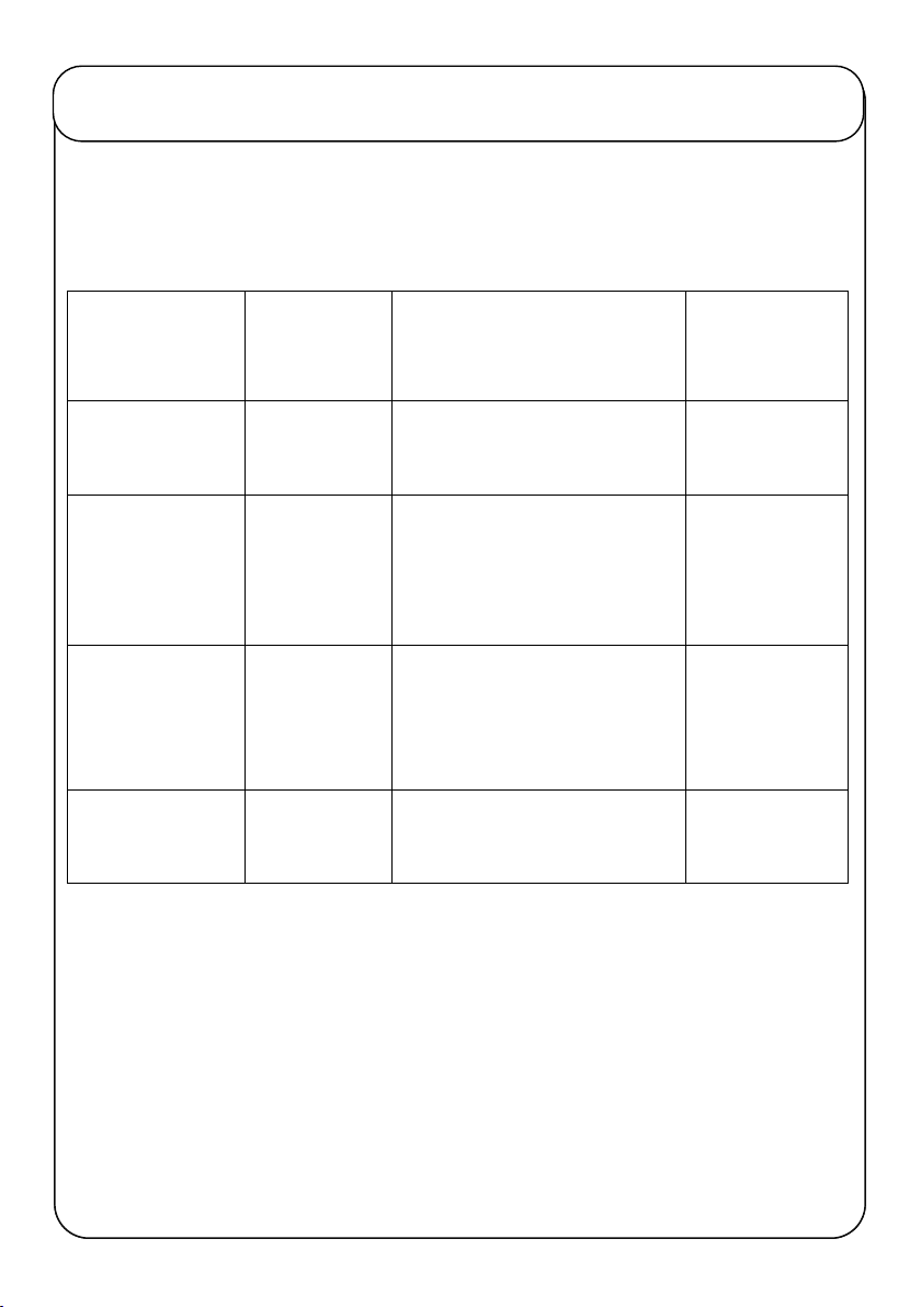
RECOMMENDED GROUPING OF PV PANELS
Recommended PV Panel Input voltage for maximum MPPT
Performance.
Battery Bank Volt
Max.PV Panel
Voltage Range
(Voc)
Examples for Grouping of PV
Panels in Series
Max.PV Panels
Applicable
in Watts
12V
30-120V
36V Voc(260w panel) x 2 in series
=72Voc=520w 550W
24V
50-150V
36V Voc(260w panel) x 2 in
series =72Voc x 2 strings in
parallel =1040w
1040W
36V 70-160V
47V Voc(335wpanel) x 2in series
= 94Voc x 2 strings in
parallel=1340w
1500W
48V 100-185V
47V Voc(335wpanel) x 3in series
= 141Voc x 2strings=2010w 2000W
Note: Solar panels should be grouped in such a way that the Open
Circuit Voltage (Voc) of the panels connected in series should not
exceed the Maximum panel voltage mentioned above for each battery
bank!
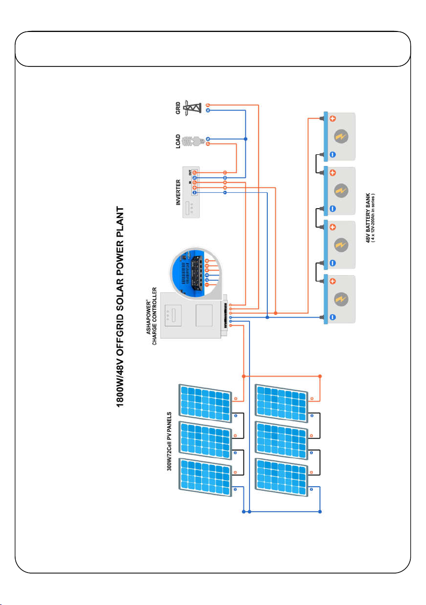
6
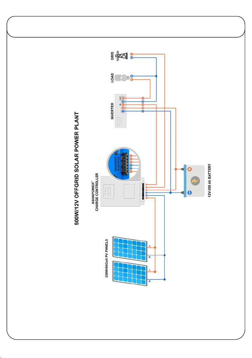
CONNECTION DIAGRAM
7
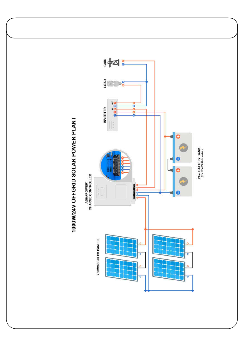
CONNECTION DIAGRAM
8
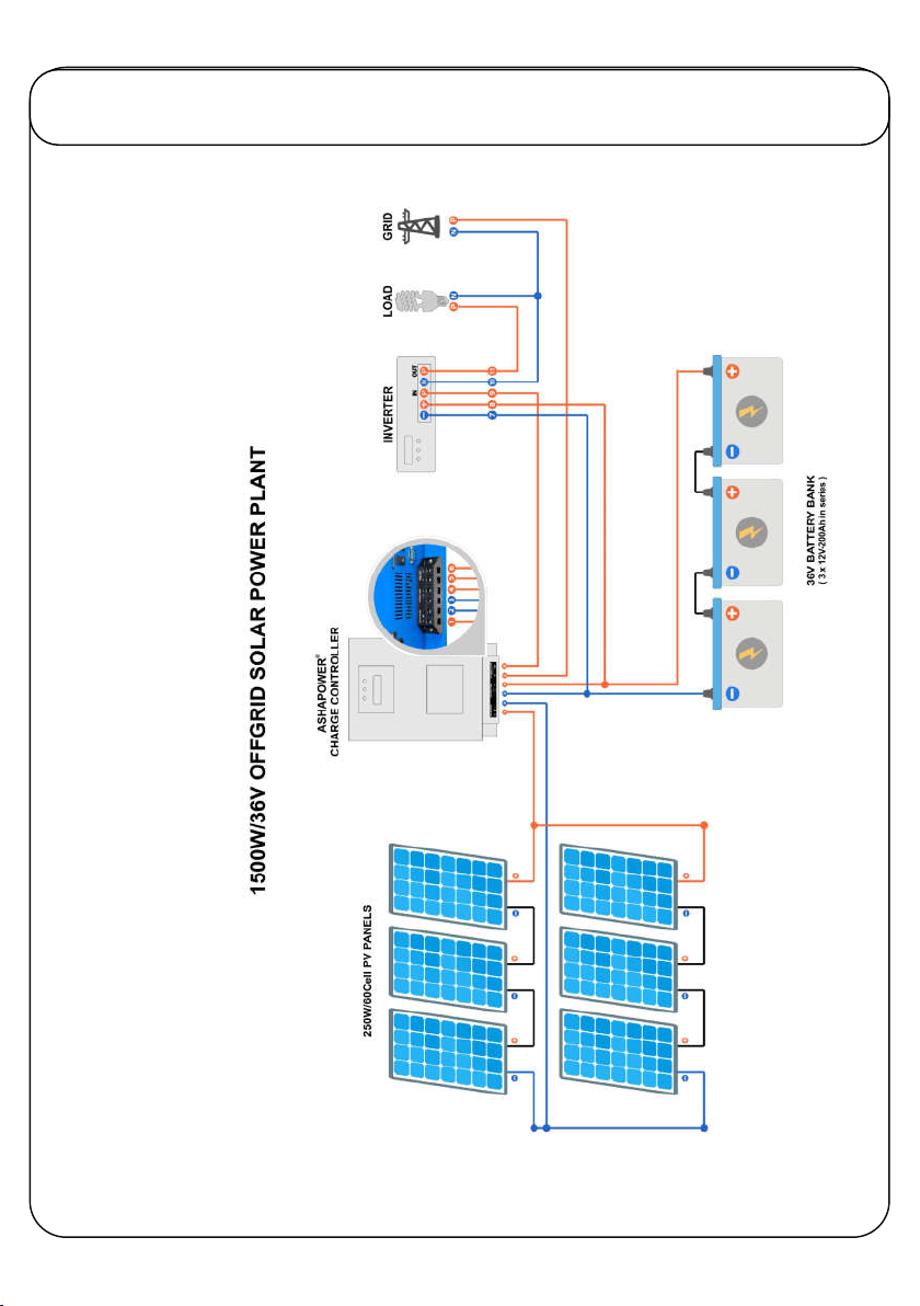
CONNECTION DIAGRAM
9
CONNECTION DIAGRAM
Questo manuale è adatto per i seguenti modelli
1
Indice
Altri manuali ASHAPOWER Controllori


