Asko DW70 Manuale utente

Service manual Dishwashers
Type: DW70

2

3
Contents
1. Introduction.................................................................................................................4
1.1 Models ................................................................................................................5
2. Technical data .............................................................................................................6
2.1 Technical information........................................................................................6
3. Installation...................................................................................................................7
4. Component information.............................................................................................9
4.1 Components and measurement values ..........................................................9
4.2 Components and function description ........................................................11
5. Programs and control unit.......................................................................................14
5.1 Programs..........................................................................................................14
5.2 Time display.....................................................................................................15
5.3 Programs and options ....................................................................................15
5.4 Wiring diagram and timer diagram................................................................17
5.5Programowdescription ...............................................................................18
5.6 Settings ............................................................................................................19
5.7 Service menu...................................................................................................25
6. Troubleshooting........................................................................................................28
6.1Dishwashingresults.......................................................................................28
6.2 Most common faults........................................................................................28
6.3 Water level........................................................................................................29
6.4 Fault indications ..............................................................................................30
7. Tools...........................................................................................................................32
7.1 Tools..................................................................................................................32
7.2 Special tools ....................................................................................................32
4
INTRODUCTION
1. Introduction
You are holding ASKO’s service manual for the DW70 generation of dishwashers.
The DW70 dishwasher series is available in ve dierent basic models, designated DW70.1,
DW70.3, DW70.4, DW70.5 and DW70.C. On the next page, we present the various panels found
on each type, making it easy to identify the dierent machines. The dierent models are named
dierently in dierent markets. The type designation is most important when identifying a particu-
lar machine model.
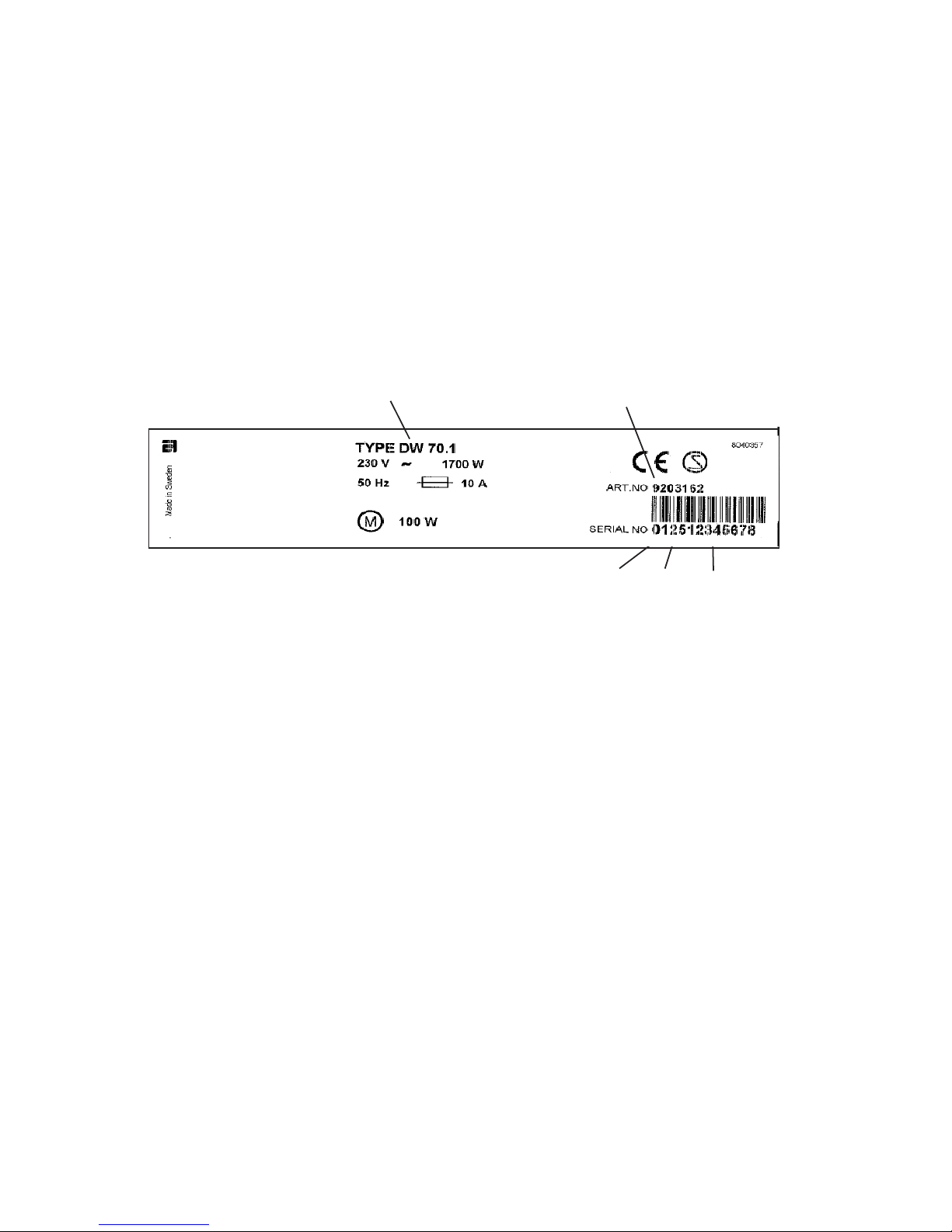
The type plate can be found on the right of the inside of the door.
The rst two digits specify the year of manufacture
while the third and fourth digits specify the week of
manufacture.
It should be easy to service a dishwasher. It is important that you, as a service technician, are aorded
conditions that enable you to work in an ecient and satisfactory way. Our hope is that this service
manual will prove a useful tool in your daily work.
Asko Appliances/After Sales
Box 344
SE-532 24 Skara
Sweden
Type designation Article number
Serial number
Year Week
5
DW70.3
The DW70.3 is available in two versions – with three and ve options respectively. The machine has six
set programs and the controls are on the top..
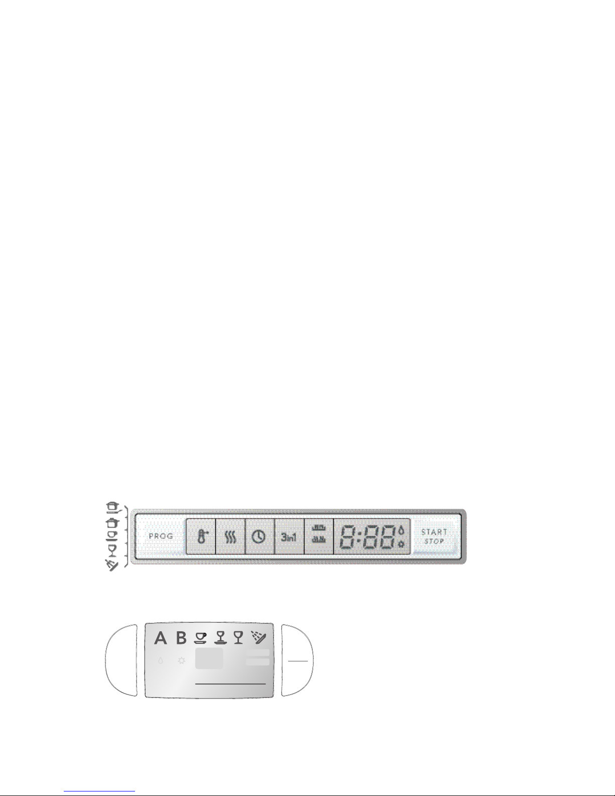
DW70.4
The DW70.4 has a number of dierent options. The machine has 14 set programs. The controls are on
the top and the display (LCD) is on the top of the panel.
1.1 Models
DW70.1
The DW70.1 is available in two versions, with either one or two options. The machine has four set
programs and the controls are on the front of the panel.
The DW70.3 and DW70.4 models are used in both fully integrated and standard models.Other control
units are only used in standard models.
INTRODUCTION
DW70.5
The DW70.5 is available in two versions – with three and ve options respectively. The machine has
ve set programs and the controls and display are at the front.
DW70.C
DW70.C
The machine has six set programs and the control and the display are on the front of the panel.
SANI SANI
S TA R TS TA R T
ENDEND
SANIWASH
Prog
StopStop
StartStart

6
2.1 Technical information
Height: 823-870 mm (32-1/4” to 35-1/2”) = for 820 mm ma
chines (XL)
863-910 mm (33-3/4” to 36”) = for 860 mm ma
chines (XXL)
Width: 596 mm (23-5/8”)
Depth: 570 mm (22-7/8”)
Weight: 42 kg / 45 kg with water softener
Water pressure: 0.03–0.2 MPa (0.3–2.0 kp/cm2), 18-176 psi
Connection: 1-phase, 230 V, 50 Hz, 10 A, (120V, 60 Hz, 15 A)**
Max. rated power: 1700 W, (1300 W)**
* According to EN 50242 standard.
** See type plate.
2. Technical data
TECHNICAL DATA
7
3. Installation
Suggested machine installations
The dishwasher can be installed built-in,
completely freestanding or partially free-
standing.
CAUTION!
Connections to electricity, water and drain
must be performed by qualied professionals.
A. Built-in
The dishwasher can be installed under a
worktop and integrated with the kitchen
cupboards. Read the instructions in the user
manual and the installation instructions for
the actual machine type.
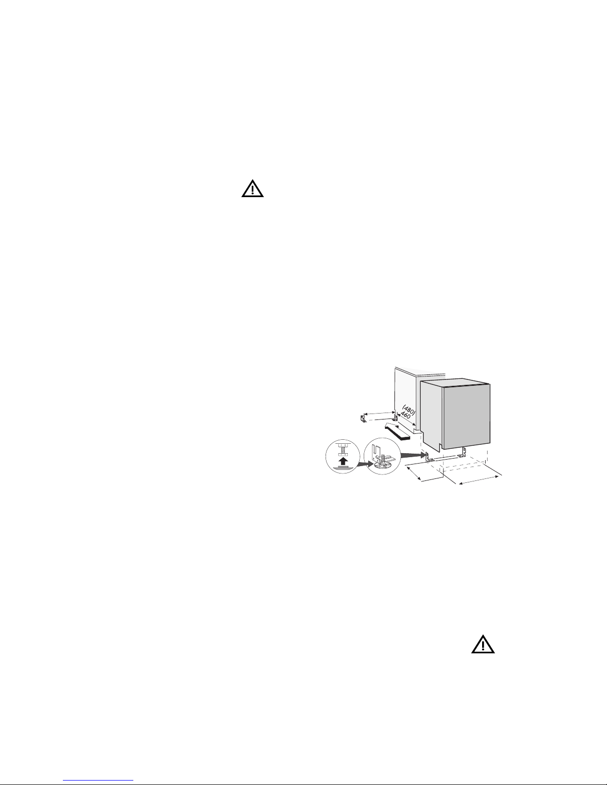
B. Freestanding
A freestanding machine must be tted with an
anti-tilt device. This comprises two brackets,
which are screwed into place as illustrated in
gure 1. An alternative to the anti-tilt device
is a counterweight that is xed directly to the
back of the machine.
Push in the machine so that the rear feet slide
into the mounting brackets. Now the machine
will not tip over if a load is placed on the
door when open. If the machine is installed
completely freestanding, side panels and a
worktop should be tted. These accessories
can be purchased where you bought the
dishwasher.
C. Partially freestanding
If you install the machine so that either side is
visible, you can t a side panel.
D.Machineswithwoodendoor
Stronger door springs are available for pur-
chase for machines with a tted wooden
door. Springs are available for various
weights and sizes of wooden door. Door
springs can be purchased where you bought
the dishwasher. Follow the instructions in
the installation manual for tting the wooden
door.
Figure 1. Anti-tilt brackets used for
freestanding installation
455-475
600
413
CAUTION!
A completely freestanding machine must be t-
ted with an anti-tilt device/counterweight.
INSTALLATION
8
Connectiontowatersupply
The supply pipe must be tted with a stop-
cock. The stopcock should be positioned
above the sink unit or at the front of the sink
unit cabinet.
The inlet pipe has a coupling with either a 1/2”
or a 3/4” internal thread, depending on the
country.
Once the machine in installed: Open the stop-
cock to ush the pipe. Check that all connec-
tions are watertight.
Electrical connection
Machines tted with a cable and plug must be
connected to an earthed socket.
Technical data
See the type plate on the right-hand side of
the door.
CAUTION!
The power cable must be disconnected or the
power to the socket turned o when work is
carried out!
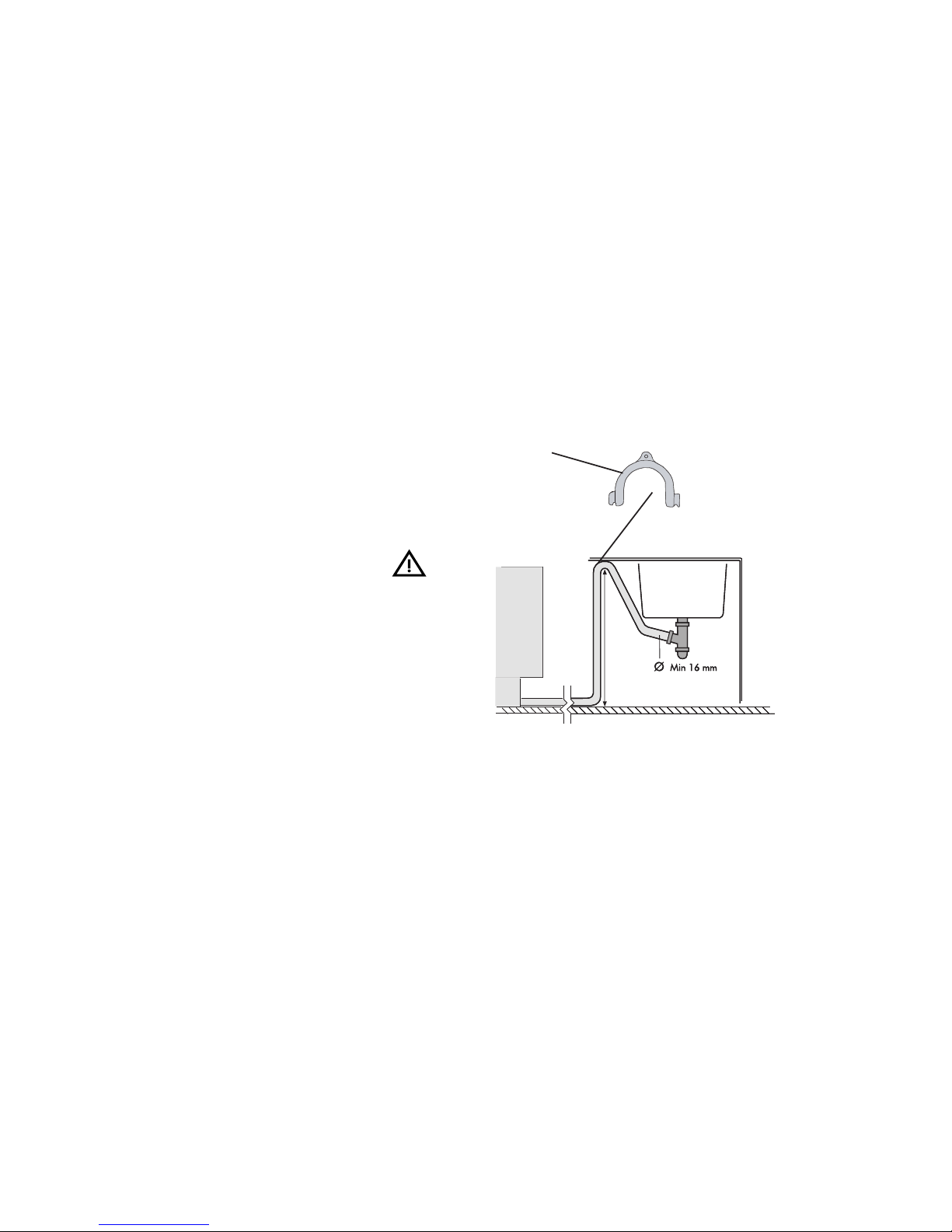
Drain connection
• The drain hose connects to a connection
nipple on the sink unit’s water trap (see illus-
tration below). Note that the hose must be at-
tached at the same height as the underneath
of the sink unit otherwise dishwater from the
sink may run down into the dishwasher (see
illustration).
• The drain hose connects to a connection
pipe on the sink unit’s water trap. It must have
an internal diameter of at least 16 mm.
• The drain hose may be extended to a maxi-
mum of 3 m. Any connections and connect-
ing pipes must have an internal diameter of at
least 16 mm.
• No part of the drain hose may be more than
950 mm above oor level.
The hose must not be routed directly to the
oor drain or similar. In such cases, the hose can
act as a siphon and empty the machine.
The hose must always discharge at least 350
mm above oor level.
• Attach the hose holder.
(Min. 350 mm and max. 950 mm above oor
level.
Figure 3.
Hose holder
Max 950 mm
Min 350 mm
INSTALLATION

9
4.Component description
4.1 Components and measurement values
The specied resistance values apply at room temperature (about 20°C/68°F)
Values within ±10% are considered normal.
COMPONENT DESCRIPTION
Article no. Position Component Measurement
value
8073779 EMC lter 680 kohm
8073780,81 EMC lter 1 Mohm
8079504 Heater 1600 W 230 V 32 ohm
8079505 Heater 1200 W 120 V 12 ohm
8078096 Thermistor 60 kohm
8073801,02 Combi disp. 230 V 1.6 kohm
8073803,04 Combi disp. 120 V 0.3 kohm
8078080
8078080
Circ. pump 220/240 V 50
Hz
Primary winding 115 ohm
Circ..pump 220-240 V 50
Hz
Auxiliary winding 260 ohm
8078082
8078082
Circ..pump 120 V 60 Hz Primary winding 31,4 ohm
Circ..pump 120 V 60 Hz Auxiliary winding 76 ohm
8078087 Drain pump 200/240 V
50 Hz, 16 l/min
148 ohm
8078089 Drain pump 120V 60 Hz,
16 l/min
26 ohm
8078084 2-3 Spray arm diverter 230 V
50/60 Hz
8.5 kohm
8078085 2-3 Spray arm diverter 120 V
60 Hz
2.6 kohm
8079502 Inlet valve single 200/240
V, 4 l/min
3.9 kohm
8079503 Inlet valve single 120 V,
4 l/min
0.95 kohm
8079500 Inlet valve fuse 220/240
V, 4 l/min
2 kohm
8079501 Inlet valve fuse 120 V, 4
l/min
0.5 kohm
8078090*
8078090 *
Softener salt water
valve 220/240 V
3 kohm
Softener mixer valve
220/240 V
2.33 kohm
10
COMPONENT INFORMATION
Flowmeter
The ow meter is tted in the air gap. The
ow meter is used to control the water intake
so that the right volume is taken in regard-
less of the water pressure. It is even possible
to program the machine for time-controlled
water intake.
The ow meter comprises an impeller with two
magnets that is driven by the water ow. On the
outside, on the ow meter housing, is a sensor,
a reed switch, which closes each time the mag-
nets pass. The number of pulses from the sensor
is proportional to the volume of the owing
water. A minimum water ow of 2 litres/minute
is required for the ow meter to operate. If
the necessary level is not reached within one
minute, the program stops.
Output signal: 220 pulses per litre.
Circulation pump
The circulation pump comprises an asynchro-
nous motor, with a pump house capacitor.
4.2Componentsandfunctiondescription
Here we present the functions and specica-
tions of the various electrical components.
Some components are only found in high-end
machines or in particular markets.
Inlet valve
Both single and safety inlet valves are used.
The valve contains a lter to stop particles then
a ow limiter to limit the ow to a maximum of
4 l/min. The valve opens when the water pres-
sure exceeds 0.3 bar and provides full ow at
about 2 bar.
Safety valve
The safety valve has two independent valve
seats, each controlled by a separate elec-
tromagnet. The valve seats are connected
in series.This doubles the safety factor. The
electromagnets are also connected in series
(electrically), which means each magnet’s
rated voltage is half the mains voltage (e.g., a
230 V valve = 2 x 115 V coils)
Single valve
The single valve comprises an electromagnet
and a valve seat.
Article no. Position Component Measurement
value
8078302*
8078302*
Softener salt water
valve 120 V
0.65 kohm
Softener mixer valve
120 V
0.65 kohm
8073830 Halogen bulb 5 W/12 V <10 kohm
8052778 Vax motor 1.1 kohm
8073850 Fan motor 230 V 0,44 kohm
8073848 Fan motor 120 V 0.18 kohm
* The number is for a complete water softener; replacement salt and mixer valves are not
available separately.
Indice
Altri manuali Asko Lavastoviglie

Asko
Asko D5456FS Manuale utente

Asko
Asko D5534XLFI Manuale utente

Asko
Asko D5893 Manuale utente

Asko
Asko D3152 Manuale utente

Asko
Asko D5544 XXL FI Manuale utente

Asko
Asko D5220 Manuale utente

Asko
Asko DW1995 Manuale utente

Asko
Asko 1485 Manuale utente

Asko
Asko D5524 Istruzioni per il montaggio

Asko
Asko DFI663XXL.U Manuale utente

Asko
Asko 1502 Istruzioni operative

Asko
Asko D5893 Manuale utente

Asko
Asko D3252 Manuale del proprietario

Asko
Asko DBI5558MIKXXL.W Manuale utente

Asko
Asko DBI4448MIB.W/1 Manuale utente

Asko
Asko DBI663PHS Manuale utente

Asko
Asko D3mmmXL Manuale utente

Asko
Asko DFI643 Manuale utente

Asko
Asko DBI865IGXXL Manuale utente

Asko
Asko D3251HDSS Manuale utente


