ASTRO-PHYSICS 3600GTO Manuale utente

1
3600GTO - Remeshing the Worm Gear
Precise meshing of the worm gear to the worm wheel is important for peak performance of your mount. A gear mesh that
is too loose will result in backlash, which can be especially problematic in declination where precise reversal of direction is
required for excellent guiding. Gear mesh that is too tight can add unnecessary stress to the motors and can result in RA
tracking that is not smooth, and in Dec guider movements that are not precise.
This document provides instructions for proper gear meshing of the 3600GTO. There are some differences between
mounts from the rst production run and mounts from subsequent production runs. Please note the version of your mount
and apply the following instructions accordingly. The rst production run has serial numbers 36003 through 36029.
These instructions can be used to eliminate backlash as dened by Astro-Physics Inc., or to back off a worm mesh
that is deemed too tight. Backlash, in particular, is a term that is often misused to describe any sort of issue in a drive
train. Before we begin, we must narrow down our denitions. Backlash and play as we dene them here are simply the
following:
Backlash (as dened by Astro-Physics):
Backlash is the result of a gap between the worm gear teeth and the worm wheel teeth. For clarity of communication, we
restrict the term backlash to ONLY apply to this worm gear to worm wheel mating. If movement can not be felt or seen in
the eyepiece when making tests that follow, the adjustments described here will not be needed. Please note that other
issues can give the false appearance of backlash when guiding or making ne adjustments with the direction buttons.
However, only the tests below will truly identify backlash as we dene it.
Play (as dened by Astro-Physics):
The movement in an axis where there was none before. It can be felt as a back and forth movement of any gearing setup
or seen as an image shift in the eyepiece where there should be none. All backlash is evidenced by play, but not all play
is necessarily backlash in the way that we dene it. For example, play can also be evidenced in reduction gears and in
bearing pre-loads. Please keep this distinction and these denitions in mind when communicating with Astro-Physics and
with the two Yahoo AP user’s groups.
Right Ascension Test for Backlash
The R.A. test is best done with the couonterwight shaft pointing down as it would in Park 2 or Park 3. Place your hand
near the end of the counterweight shaft and move the shaft back and forth as if to rotate the R.A. axis. This test can be
done with the mount alone on its pier or with the telescope and counterweights attached. The play you are looking for is
rather subtle. You will have a better sense of feel if you hold the counterweight shaft with your ngertips. Be sure that the
counterweight shaft is not loose and wiggling. Because of the geometry of a German Equatorial mount, it is rather difcult
to observe the movement in an eyepiece unless you have an assistant.
If no play is felt or seen, then you do not have an R.A. backlash problem.
If play is felt or seen in the telescope eyepiece when moving the shaft back and forth, proceed with the adjustment as
described below.
Declination Test for Backlash
Place your hand near the end of the telescope focuser, or at the end of the cradle plate, if the telescope is off the mount.
Be sure that whatever you are using is itself solid and ex-free. Move the telescope or plate back and forth as if to rotate
the Dec. axis. This test must be done with the assembled mount on its pier. Again, the play you are looking for is rather
2
subtle. You may want to grab the scope or plate at each end and use two hands. Again, ngertips will tend to give the
most accurate sense of feel. This is also a case where an assistant can be useful to observe movement in an eyepiece.
If no play is felt or seen, then you do not have a Dec. backlash problem.
If play is felt or seen in the telescope eyepiece, proceed with the following adjustment.
Remember that the denitions above relate to backlash which is a gear mesh that is too loose. The instructions below
deal with both conditions: backlash and over-tightened mesh. If the mount’s axis is making noise, like the motor is
straining, or it is jumping and stuttering, the worm gear mesh may likely be too tight against the worm wheel.
It is important to make this engagement diagnosis to eliminate it from the other possibilities, such as motor or
servo controller issues.
NOTE: The action to follow will negate the PE correction established by PEMPro. After the check or
test the PEMPro runs will have to be done again. Any movement of the worm other than by the motor
drive will negate the PE correction.
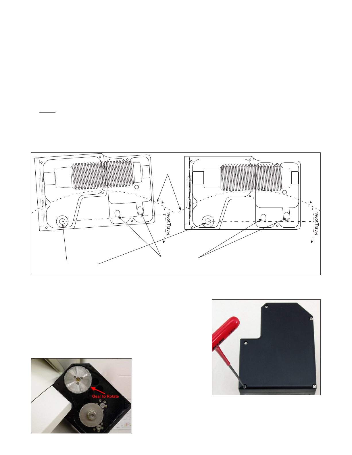
The basic design of the gear meshing system is the same for all of the 3600GTO mounts produced. The system is based
on a pivot bearing on one side of the motor / gearbox assembly, and a pair of lock-down bolts on the other side.
Adjusting the Worm Gear Mesh on your 3600GTO Mount
The following instructions apply to both axes. There are some differences
between mount production runs, but they will be noted in the text below.
Do Not loosen the two screws that retain the worm drive until you do the
following:
Shut off the GTOCP3 servo drive and remove the 5 screws that secure the
reduction gearbox cover using a 3/32” hex key (image right). Then remove
the top center spur gear, exposing the two gears below.
Place your ngers on the gear
that is attached to the worm.
This is the gear having three
attachment screws clearly
visible. Rotate the gear with
your ngers in both directions.
This gear should turn freely in both directions without backlash when properly
adjusted (image at left).
If you felt backlash in the system, you should nd that the gear rotates easily in
both directions. You will therefore be adjusting the mesh a bit tighter. If the
gear is difcult to turn, then the mesh is too tight, and you will be loosening the
Worm Wheel
Pivot Bearing
DO NOT LOOSEN!
Locking Bolt Slots
(Pivot Travel Greatly Exagerated)
3
mesh. Whether tightening or loosening, you are probably best off thinking in terms of setting the mesh anew, rather than
adjusting the existing mesh. The tendency if you try to tighten or loosen an existing mesh by a tiny amount is to overshoot
and put yourself into a back and forth cycle of too tight and too loose. Approach the re-mashing as if you were performing
the original meshing of a newly assembled system, and you will have a greater chance of success.
NOTE: In mounts from the rst production run, you may nd that the gear turns freely in one direction and considerably
harder in the other. This can cause poor tracking and/or motor stalls in the more difcult direction, and could eventually
lead to motor damage. The approach is to concentrate on the difcult direction of rotation in your adjustments.
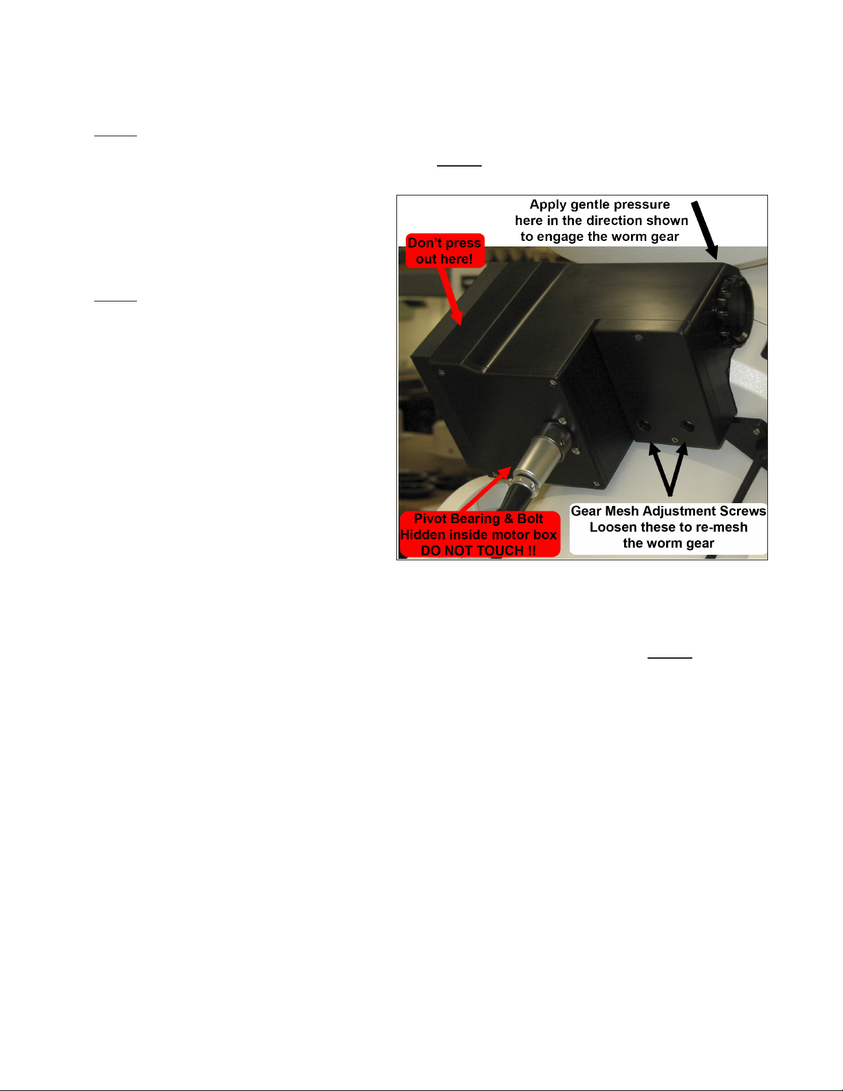
At this point, you are ready to start the actual
adjustment. To begin, loosen the two 1/4-20 Gear
Mash Adjustment Screws (SHCS) just enough to
slightly move the worm away from the wheel. DO
NOT REMOVE THESE BOLTS, as they hold shims
in place.
NOTE: There is a third bolt that is inside the motor
housing – behind the receptacle for the Y-cable plug.
When the two bolts indicated above are loosened,
the entire motor / gearbox will pivot a very slight
amount on this third bolt. The bolt is actually part of
a thrust bearing system and MUST remain very tight.
DO NOT try to loosen this bolt. We considered not
even mentioning this bolt so that no one would be
tempted to loosen it. However, we felt it was more
important that you understand how things work. We
trust that you will believe us, and that you will not
loosen this when making your adjustments. Please
see the diagram on page 2.
Pivot the motor gearbox counterclockwise to loosen
the mesh as shown in the diagram on page 2.
Now, gently work the motor / gearbox down into full
mesh by pressing and jiggling the worm slightly by
rocking the worm’s spur gear back and forth. Apply only very light pressure, and press directly over the worm, above the
knurled end cap, rather than out on the back side of the box as shown in the photo above-right.
While pressing down gently, rotate the worm back and forth via its spur gear at least a full rotation in each direction. If one
direction rotates a bit harder than the other, especially in the case of a rst production run mount, be sure to rotate the gear
in the more difcult direction to determine the proper mesh. Continue to rotate the gear in the more difcult direction as
you gradually apply pressure to the worm. (For 1st production run mounts, ignore for now how free the rotation is in the
opposite direction.)
You will reach a point where any continued increase of the pressure on the gearbox begins to affect the ease with which
the worm turns. You should begin to feel this increased tightness in the worm with no more pressure than can be applied
with a single nger. If you have gone too far, simply remove the pressure and continue to turn the worm gear. The
mesh should loosen up a bit as you turn the worm, and you can repeat the process. The idea is to just reach, but NOT to
exceed, the exact point where the worm begins to feel more resistance.
Keeping the light pressure on the motor / gearbox, snug up the two gear mesh adjustment screws. Alternate your
tightening as follows:
1. Start with the screw on the right and bring it to contact - just barely snug.
2. Repeat with the left screw.
3. Bring the right-hand screw to one-half tight.
4. Repeat with the left screw.
5. Fully tighten the right-hand screw.
6. Repeat with the left screw.
Check rotation again in both directions. If free in both directions, retest for backlash as described starting on page 1. If
Motor / Gearbox shown
is from rst production run

4
rotation is free and there is no backlash, you have nished the operation. Replace the top center spur gear and the gear
box cover.
Alternate Method for Adjusting the Gear Mesh
There is another technique that can be employed with success, especially if you are having difculty with the above
procedure. This procedure should ONLY be used on a system that is properly balanced. Much of this procedure is the
same. Please follow the instructions up through the point where you have loosened the gear mesh adjustment screws.
At this point, you should have identied if there is a more difcult direction to turn the worm wheel. It is very important
that you know whether one direction has more resistance than the other, and that you know which direction (clockwise or
counterclockwise) is the more difcult to turn.
NOTE: Read the following instructions through completely once or twice before starting this procedure. You will be
actually operating the mount, albeit at a slow rate, but you don’t want to have to stop to gure ouot what comes next once
the procedure is started!!
1. Replace the center spur gear in the gear reduction train so that the motor is again engaged with the worm.
2. Power up the system with the keypad attached.
3. Set the keypad button rate to 64X.
4. Determine which direction on the keypad corresponds to the direction of highest resistance in the worm gear. Remem-
ber that the center spur gear that you just replaced will be turning in the OPPOSITE direction from the worm gear!
5. Press the corresponding direction button from step 4 above, and while holding the button down, remove the keypad
plug from the GTOCP3 control box. The mount will continue to move at the 64X rate.
6. Apply pressure as described for the rst procedure trying to reach the point where you just begin to hear a slight
change in the motor’s sound indicating that the worm’s resistance is increasing. Because the worm is turning, releas-
ing or reducing the pressure will relax the mesh again. Find the exact point just before tension begins to increase.
7. While keeping the pressure on the motor / gearbox constant, tighten up the gear mesh adjustment screws as described
above for the original procedure.
8. Plug the keypad back in and bump the direction button to stop the motion of the axis.
9. Remove the center spur gear and re-test the rotation in both directions. Follow this with the tests for backlash as
described starting on page 1.
10. Repeat if necessary, but you may want to move the mount’s position back to where you started before attempting the
repeat.
If rotation is free and there is no backlash, you have nished the operation. Replace the top center spur gear and the
gear box cover.
Indice
Altri manuali ASTRO-PHYSICS Telescopio

ASTRO-PHYSICS
ASTRO-PHYSICS PASILL4 Manuale utente

ASTRO-PHYSICS
ASTRO-PHYSICS 400QMD Manuale utente

ASTRO-PHYSICS
ASTRO-PHYSICS 900GTO Manuale utente

ASTRO-PHYSICS
ASTRO-PHYSICS 400GTO Manuale utente

ASTRO-PHYSICS
ASTRO-PHYSICS GTOCP2 Manuale utente

ASTRO-PHYSICS
ASTRO-PHYSICS 400 Manuale utente

ASTRO-PHYSICS
ASTRO-PHYSICS Mach1GTO Manuale utente

ASTRO-PHYSICS
ASTRO-PHYSICS 1200 Manuale utente


