Atag A200SOV Manuale operativo

8G.51.70.02/08.11 Changes reserved.
Installation & Servicing
Instructions
A200SOV
Open vent heat only boiler
These instructions to be retained by user.
Boiler G.CNo
A200SOV 41-310-15
CE PIN 0063BT3195

Installation&ServicinginstructionsATAGA200SOV
2
Explanation of the control panel display and keys
%
ba
r
°C
(OK )
( ESC)
+
--
i
R
+
FlameIndication that the boiler is on
Bell Error indication
Spanner Service-mode or blocking
Radiator Indication that the boiler is on
Heating program
Scrolland+/-function OKandEscape(ancillaryfunction)
DHW setting not applicable Setting of boiler temperature (max. supply temperature)
Information key Reset key
LCD display with backlight
Directly operated soft cushion keys
Standard display read out:
The default view of the display shows the ow water temperature (°C) of the boiler.
In this case with heat request (radiator symbol) and boiler on (ame symbol)

Installation&ServicinginstructionsATAGA200SOV
3
Content
1 Introduction ....................................................................................................................................4
2 Rules ............................................................................................................................................4
3 Delivery package ............................................................................................................................6
4 Boiler description ............................................................................................................................6
5 Mounting the boiler .........................................................................................................................7
5.1 Dimensions .........................................................................................................................8
6 Connecting the boiler .....................................................................................................................9
6.1 Open vent heating system ..................................................................................................9
6.2 Heating systems with plastic pipes ...................................................................................10
6.3 Gas connection ................................................................................................................. 11
6.4 Condensation drain pipe ................................................................................................... 11
6.5 Flue gas exhaust system and air supply system ..............................................................13
6.5.1 Dimensioning of the ue gas and air intake duct ............................................................17
7 Electrical connection ....................................................................................................................18
7.1 Y-plan connection ..............................................................................................................18
7.2 Electrical diagram .............................................................................................................19
8 Filling the system .........................................................................................................................20
8.1 CH Installation ...................................................................................................................20
8.2 Gas supply ........................................................................................................................20
9 Boiler controls ..............................................................................................................................21
9.1 Explanation of the control keys .........................................................................................22
10 Commissioning the boiler .............................................................................................................23
10.1 CH system ........................................................................................................................23
10.2 Pump function ...................................................................................................................23
10.3 Settings .............................................................................................................................24
10.4 Activating the factory setting (green key function) ............................................................25
11 Isolating the boiler .......................................................................................................................26
12 Commissioning .............................................................................................................................26
12.1 Checking the O2 ................................................................................................................27
12.2 Maintenance activities .......................................................................................................28
12.3 Maintenance frequency .....................................................................................................30
12.4 Warranty ............................................................................................................................30
13 Error message .............................................................................................................................30
14 Technical specications ................................................................................................................31
15 Parts of the boiler .........................................................................................................................32
16 Declaration of Conformity .............................................................................................................33
17 Kiwa certicate .............................................................................................................................34
Benchmark Checklist ...................................................................................................................35
Service Record .............................................................................................................................36
Work on the installation should only be carried out by qualied personnel
with calibrated equipment.

Installation&ServicinginstructionsATAGA200SOV
4
1 Introduction
These instructions describe the functioning, installation, use and primary maintenance of
ATAG central heating boilers for the United Kingdom and Ireland. Where necessary the
different regulations for each country are separately described.
These instructions are intended for the use by Gas Safe Register approved contractors
or registered Bord Gais installers in connection with the installation and putting into
operation of ATAG boilers. It is advisable to read these instructions thoroughly, well in
advance of installation. Separate instructions for use are supplied with the boiler for users
of ATAG central heating boilers. ATAG is not liable for the consequences of mistakes
or shortcomings which have found their way into the installation instructions or user’s
manual. Further, ATAG reserves the right to alter its products without prior notication.
When delivering the boiler, give the customer clear instructions concerning its
use; present the customer with the user’s manual and card.
Each boiler is tted with an identication plate. Consult the details on this plate to verify
whether the boiler is compliant with its intended location, e.g.: gas type, power source
and exhaust classication.
On completion of the installation the installer or commissioning engineer must ll out
and complete the Benchmark Commissioning Checklist found on page 33 of this manual
and hand this to the customer for future record keeping. The Benchmark Service Record
must also be completed by the service agent following each service call, and return to
the customer. A copy of the Benchmark Commissioning Checklist must be returned to
ATAG Heating along with the warranty registration card to register the appliance for the
standard warranty benets.
Relevant Installation, Service and User manuals:
- ATAG Monopass Flue system guide
2 Rules
The following regulations apply to installation of ATAG central heating boilers:
Legislation and Regulations.
Gas Safety (Installation and Use). All gas appliances must by law, be installed by a competent
person, eg. Members of Gas Safe Register and in accordance with the current Gas Safety
Regulation. Failure to install appliance correctly could lead to prosecution.
All Gas Safe Register approved contractors carry a Gas Safe Register ID Card and have
a registration number. You can call Gas Safe Register direct on 01256 372300
In addition to the above regulations this appliance must be installed in compliance with the
current IEE Regulations, the Building Standards (Scotland Consolidation) Regulations.
Regulations and bye laws of the Local Water Authority and the Current Health and Safety
Regulation.
The Benchmark Scheme
Benchmark places responsibilities on both manufacturers and installers. The purpose
is to ensure that customers are provided with the correct equipment for their needs,
that it is installed, commissioned and serviced in accordance with the manufacturer’s
instructions by competent persons and that it meets the requirements of the appropriate
Building Regulations. The Benchmark Checklist can be used to demonstrate compliance
with Building Regulations and should be provided to the customer for future reference.

Installation&ServicinginstructionsATAGA200SOV
5
Installers are required to carry out installation, commissioning and servicing work in
accordance with the Benchmark Code of Practice which is available from the Heating
and Hotwater Industry Council who manage and promote the Scheme.
Visit www.centralheating.co.uk for more information.
Ireland:
- Irish standard 813
- Domestic gas installations
The current, Electricity at Work Regulation must be complied with and also be in
accordance with the relevant and current editions of the British Standards.
The ATAG A boiler is a certied appliance and must not be modied or installed in any
way contrary to this Installation Manual. Manufacturers instructions must not be taken
in any way as overriding statutory obligations.
These boilers must be connected according to these instructions and all installation norms
in respect of the part of the boiler to be connected.
Observe the following rules of safety:
- All work on the boiler must take place in a dry environment.
- ATAG boilers may never be in operation without their housing, except in connection
with maintenance or adjustments (see Chapter 13 and 14).
- Never allow electrical or electronic components to come into contact with water.
Carry out the following tasks in connection with maintenance, etc. to an already-installed
boiler:
- Shut down all programs
- Close the gas tap
- Remove the plug from the wall socket
Take note of the following when maintenance or adjustments are needed:
- The boiler must be able to function during these activities; for this reason, the boiler’s
supply voltage, gas pressure and water pressure must be maintained. Ensure that
there is not a source of potential danger during these activities.
Following maintenance or other activities; always check the installation of all parts
through which gas ows (using leak-search spray).
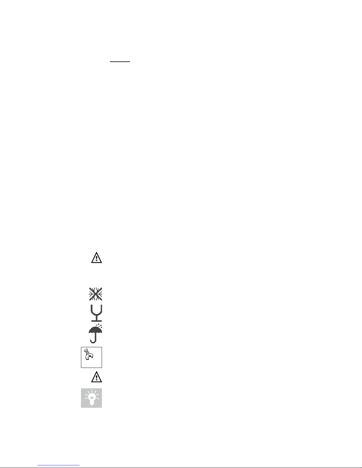
The following (safety) symbols may be encountered in these installation instructions and
on the boiler:
This symbol indicates that the boiler must be stored away from frost.
This symbol indicates that the packaging and/or contents can be damaged as a
result of insufcient care taken during transport.
This symbol indicates that, whilst still in its packaging, the boiler must be
protected from weather conditions during transport and storage.
KEY-symbol. This symbol indicates that assembly or dismantling, must be
carried out.
ATTENTION symbol. This symbol indicates that extra attention must be paid in
connection with a particular operation.
Useful tip or advice

Installation&ServicinginstructionsATAGA200SOV
6
3 Delivery package
The boiler is delivered ready for use. The delivery package is composed as follows:
• Boiler with cover;
• Automatic air vent (in boiler);
• Gas isolation valve;
• Suspension bracket;
• Cable feed through;
• Fittings consisting of plugs and screws;
• Drawing template;
• Installation instruction;
• User manual;
• Warranty Card and Benchmark logbook.
The ATAG A is mainly equipped with 230V electrical components.
The following components are not present in the boiler as a standard and should be
included in the installation according to the requirements (supplied by third parties):
• Circulation pump
• Programmer, room thermostat and cylinder thermostat.
4 Boiler description
The ATAG A is a room sealed, condensing and modulating CH boiler.
The boiler is equipped with a compact stainless steel heat exchanger with smooth pipes.
It is a well thought-out principle using sustainable materials.
The boiler burns (natural) gas to supply heat. This heat is transferred in the heat
exchanger to the water in the CH installation. The rapid cooling off of the ue gases
causes condensation. This results in a very high yield. The condensation that is formed,
has no negative impact on the heat exchanger and it's operation, and is removed through
the internal siphon.
The boiler is equipped with an intelligent control system: CMS (Control Management
System). Each boiler anticipates the heat request of the heating installation. This will
cause the boiler to tune its capacity to the installation. This means that the boiler will
function longer and at a low level.
The boiler has been tested according to valid CE* standards and has a CE* certicate
and SEDBUK A-rating.
Statement: No banned materials including asbestos, mercury, CFC's have or will not be
included in the product.
Room sealed boiler
Theboilerretrievesits
combustionairfromthe
outsidethendischarges
thefluegassestothe
outside.
Condensing
Retrievesheatfromthe
fluegasses.Watercon-
densatesontheheat
exchanger.
Modulating
Higherorlowerburning
accordingtotheheat
demand.
Stainless Steel
Supersolidkindofsteel
whichkeepsitsquality
forlife.Itwillnotrust
orerodeincontrastto
compositionmaterials,
likealuminium.

Installation&ServicinginstructionsATAGA200SOV
7
5 Mounting the boiler
The room where the boiler will be placed must always be frost free. The boiler casing is
splash water tight (IPX4D) and is suitable to be installed in e.g. a bathroom.
It is NOT necessary to have a purpose provided air vent in the room or internal space in
which the boiler is installed. Neither is it necessary to ventilate a cupboard or compartment
in which the boiler is installed, due to the extremely low surface temperature of the
boiler casing during operation. Therefore the requirements of BS 6798, Clause 12, and
BS5440:2 may be disregarded.
The boiler can be mounted practically to any wall with the suspension bracket and the
enclosed xing equipment. The wall must be at and of sufcient strength in order to be
able to carry the boiler weight with its water content.
Above the boiler there must be at least 250 mm working space in order to be able to t a
coaxial ue system or a twin supply. On the left side of the boiler at least 50 mm and on
the right side 10 mm must be reserved to allow tting or removing of casing. The location
of the boiler can be determined by using the template.
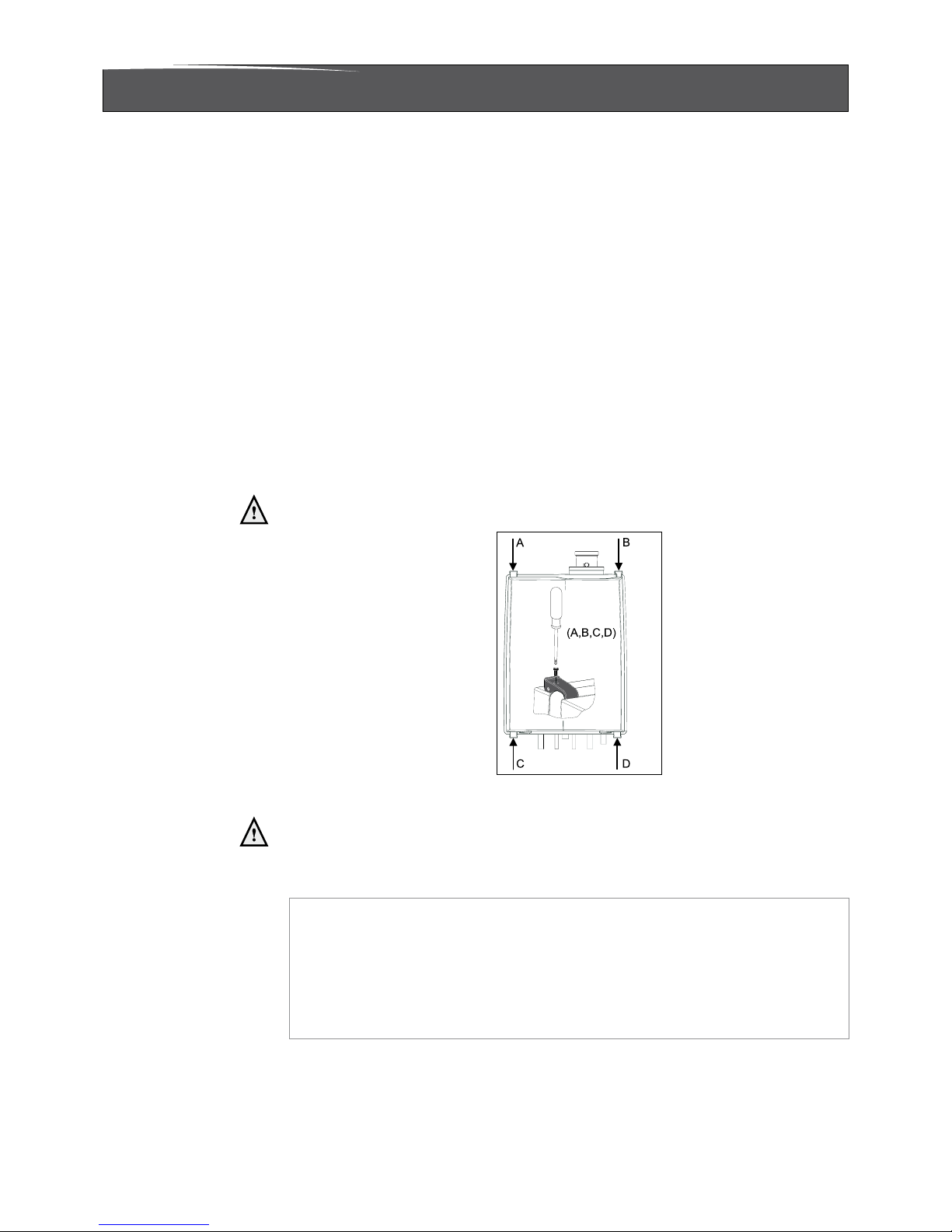
Before hanging the boiler remove the outer boiler casing. The cover is also the air cabinet
and is attached to the rear wall with four quick fasteners (A, B, C and D) (see gure 1).
Secure the quick fasteners with the screws (A, B, C and D) at the back of the
cover.
Lift the boiler only by the boilers rear wall.
Figure 1
Lifting and carrying precautions:
- Lift only a manageable weight, or ask for help.
- When lifting the boiler, bend the knees, and keep the back straight and feet
apart.
- Do not lift and twist at the same time.
- Lift and carry the boiler close to the body.
- Wear protective clothing and gloves to protect from any sharp edges.

Installation&ServicinginstructionsATAGA200SOV
8
5.1 Dimensions
dimensions (inmm) Figure2
connectiondiameters tabel2
keteltype A200SOV
A/B Flue gas / Air intake mm 60/100
Gas connection ½"
int.
CH Flow connection mm 22
CH Return connection mm 22
Condensate drain connection mm 22
wall
ceiling
minimum 250mm
minimum 10 mm
Top view
Front viewLeft side view
Bottom view

Installation&ServicinginstructionsATAGA200SOV
9
6 Connecting the boiler
The boiler has the following connection pipes;
- The central heating pipes.
These can be connected to the installation by means of compression ttings / adapter
ttings;
- The gas pipe.
It is provided with a female thread into which the tail piece of the gas isolation valve
can be screwed;
- The condensation drain pipe.
It consists of a 22mm plastic pipe. The drain pipe can be connected to this by means
of an open connection. If the open connection is tted in a different location, then the
pipe can be lengthened by means of a 32 mm PVC sleeve;
- The ue gas exhaust system and air supply system.
It consists of a concentric connection 60/100 mm.
Isolation valves are not permitted to be installed on open vent boilers.
It is advisable to spray-clean all of the boiler’s connecting pipes and/or to spray-
clean/blow-clean the installation before connecting it to the boiler.
6.1 Open vent heating system
This boiler is only suitable for installations that have been equipped with “open”
expansion tanks (Open vent).
Connect the Open vent heating system according to the current regulations.
450 mm
Min. height
1000 mm
Min.
150 mm Max.
Heating
circuit
DHW
cylinder
Boiler
22 mm (Min.) vent feed and
expansion cistern
15 mm (Min.) cold feed
Pump
22 mm (Min.)
Automatic by-pass
Open vent heating system
Recommended relationship
between pump, cold feet and vent.
Scheme open vent system Figure 3

Installation&ServicinginstructionsATAGA200SOV
10
The boiler pipes have to be connected to the installation by means of compression
ttings. For connecting to thick-walled pipe (welded or tted), adapters should be used.
When removing the plastic sealing caps from the pipes, contaminated testing
water may be released.
If all, or a substantial part of the radiators have thermostatic radiator valves, a pressure
regulator has to be used to prevent ow problems in the installation. The pressure
regulator used should have the same diameter as the connecting diameter of the supply
and return pipe of the boiler. See also chapter 5.1.
An Adey Magnaclean or Fernox TF1 lter is recommened to be installed,
preferably on the return pipework as close to the boiler practitable.
Additives in the installation water are only permitted in consultation with the
country distributor. ATAG Heating UK Ltd recommend the use of either Fernox
or Sentinel products.
6.2 Heating systems with plastic pipes
When connecting or using an underoor heating system, designed with plastic pipes, or
plastic pipes are used elsewhere in the installation,one should ensure that the plastic
pipes used comply with the DIN 4726/4729 standard. It is set out in this standard that the
pipes may not have oxygen permeability higher than 0.1 g/m³.d at 40°C. If the system
does not comply with this DIN standard, the underoor heating component will have to
be separated from the central heating appliance by means of a plate exchanger.
No recourse can be made to the terms of the warranty in the event of failure to
observe the regulations pertaining to plastic underoor heating pipes.
Altri manuali per A200SOV
1
Questo manuale è adatto per i seguenti modelli
1
Indice
Altri manuali Atag Caldaia

Atag
Atag XL-F Series Manuale utente

Atag
Atag IC series Manuale utente

Atag
Atag iC Economiser 27 Guida rapida

Atag
Atag Q 25S Manuale utente

Atag
Atag A200S Nota di rilascio

Atag
Atag XL75W Nota di rilascio

Atag
Atag XL-W Series Manuale utente

Atag
Atag QR Series Manuale utente

Atag
Atag i24C Guida rapida

Atag
Atag IS 12 Nota di rilascio

Atag
Atag Q 51C Manuale utente

Atag
Atag iR 12 Nota di rilascio

Atag
Atag Premier E-SHR 15 Guida utente

Atag
Atag A200S Nota di rilascio

Atag
Atag Q 25S Nota di rilascio

Atag
Atag XL75F Nota di rilascio

Atag
Atag 41-310-12 Manuale utente

Atag
Atag i Series Manuale utente

Atag
Atag A200SOV Manuale utente

Atag
Atag iC 24 Nota di rilascio