ATECH BC 700 Manuale utente

Smart Bottom Blowdown Controller
IM-BC70017C
BC 700
www.atech-ltd.com
BC 700
Installation and Operating Instructions
Smart Bottom Blowdown Controller

Smart Bottom Blowdown Controller
1. SAFETY INFORMATIONS 3
2. DESCRIPTION & FUNCTIONS 4
3. TECHNICAL SPECIFICATIONS 5
4. INSTALLATION 5
4.1 Installation 5
4.2 Wiring 6
5. FUNCTIONS and CONFIGURATIONS 7
5.1 Display Definitions and Button Functions 7
5.2 Changing Function Configurations 8
5.2.1 Startup Screen 8
5.2.2 Main Menu 8
5.2.3 Interval 8
5.2.4 Blowdown 8
5.2.5 Reset 9
5.2.6 Blowdown Counter Reset 9
5.2.7 Total Blowdown Time Reset 9
5.2.8 Alarm Counter Reset 9
5.2.9 System Mode Auto/Off 9
5.2.10 Open & Close Valve 10
5.2.11 Other Controllers 10
5.2.12 Valve & Alarm Test 10
5.2.13 Modbus Setup 11
5.2.14 Password 11
5.2.15 Default Settings 11
5.2.16 Software Version 11
6. COMMISIONING 12
7. MAINTENANCE 12
IM-BC70017C Page 2
www.atech-ltd.com
Giyim Kent 16. Sok. No: 79 Esenler/İstanbul - Turkey
P : 0.212.438 42 38 F: 0.212.438 42 58
ATECH ENDÜSTRİYEL ÜRÜNLER SAN. VE TİC. LTD. ŞTİ.
BC 700
CONTENTS

Smart Bottom Blowdown Controller
1. SAFETY INFORMATIONS
Safety!
National and local regulations must be taken into consideration while electrical or mecanical installation.
Warning!
Please make sure to remove the main supply before installation.
Otherwise this may cause damage to the product, personal injuries or even death.
The manufacturer expressly rejects any claims for damage caused by improper installation.
IM-BC70017C Page 3
www.atech-ltd.com
BC 700
Installation, commissioning and maintenance of this device must be done by a qualified person in compliance with the
operating instructions. Otherwise device and related equipments may be damaged and personnel may be injured.

Smart Bottom Blowdown Controller
2. DESCRIPTION & FUNCTIONS
Please refer to "BCV 700 Installation and Operation Manual for Automatic Bottom Blowdown Valve" for detailed
information on the Bottom Blowdown Valve before assembly.
: Aliminyum
Figure 1 Application of Automatic Blowdown Control System
IM-BC70017C Page 4
BC 700
www.atech-ltd.com
Automatic Bottom Blowdown System ensures right and perfect bottom blowdown of precipitated solids at the bottom of
the boiler. It provides key operated manual control and full automatic control. It prevents waste of water and boiler water
chemicals, therefore fuel and energy losses because of too much blowdown. Blowdown can be performed at desired
ranges and times.
BC 700 Smart
Bottom Blowdown
Controller
BCV 700 Bottom
Blowdown Valve
Steam Boiler
Smart Bottom Blowdown Controller
3. TECHNICAL SPECIFICATIONS
Enclosure : IP 40 - EN 60529
Maximum ambient temperature : 55 °C
Main supply voltage : 230 V +/– 10 %, 50/60 Hz
115 V +/– 10 %, 50/60 Hz (Optional)
Frequency : 50 Hz
Maximum power consumption : 3 VA
Material : Plastic
Output signal : Relay contacts
Indicators and adjustors : 1 yellow LED for signalling “Power”,
1 green LED for signalling “Blowdown”,
1 red LED for signalling “Test”,
1 red LED for signalling “Alarm”,
1 button “ALARM” for checking alarm,
1 button “RESET” for resetting the alarm,
4 pushbuttons for parameter settings.
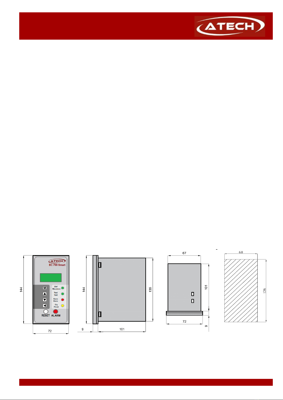
Dimensions (height x depth x width) : 144 x 110 x 72 mm
Weight : 0,5 kg
4. INSTALLATION
Installation, commissioning and maintenance of this device must be done by a qualified person in compliance
with the operating instructions.
4.1 Installation to panel
Smart Bottom Blowdown Controller BC 700 is front panel mounting enclosure type and can be applied to the front
panel with two screw clamps supplied.
Allow 20 mm minimum clearance all round the unit for air circulation.
Figure 2 Panel cut out dimensions of Smart Bottom Blowdown Controller BC 700
Please refer to "BCV 700 Installation and Operation Manual for Automatic Bottom Blowdown Valve" for detailed
information on the Bottom Blowdown Valve before assembly.
IM-BC70017C Page 5
BC 700
www.atech-ltd.com

Smart Bottom Blowdown Controller
4.2 Wiring
Wiring between Smart Bottom Blowdown Controller BC 700 and namur solenoid valve, 3x1 mm2 cable can
be used. Wiring between controller and limit switch, 2x1 mm2normal cable can be used.
The locations of terminals should not be changed.
If it is considered that the controller has phase connetiction to terminal 10 to terminal 17, then the terminal 1
through 9 of the controller should never be connected to the terminal 10 through terminal 17.
Otherwise, this could cause damage to equipment and even damage to people.
Figure 3 Smart Dip Blowdown Controller BC 700 electrical connection diagram
Note : Relays are shown in the “power-off” position (alarm condition)
Warning!
At the all phase inputs of the controller, must be used 3A fuse (non-delay type).
Limit Switch: Limit switch gives “valve opened” and “valve closed” signals to BC 700.
Other BC 700 s: This function prevents blowdowns that happening at the same time to common blowdown line.
Burner: With this function BC 700 do not blowdown while burner is operating.
Alarm: While blowdown, if valve is not opened or not closed properly, BC 700 gives alarm relay output.
Namur Solenoid Valve: It opens and closes the valve using the signals sent from BC 700
IM-BC70017C Page 6
BC 700
www.atech-ltd.com

Smart Bottom Blowdown Controller
5. FUNCTION AND CONFIGURATIONS
5.1 Display Definitions and Button Functions.
LCD Screen
Enter or return to main menu
Blowdown Led
Scroll up menus and
increase digits Test Led
Scroll down menus and Alarm Led
decrease digits
Power Led
Enter to functions, submenus
and pass to next digit while
changing a function value
Alarm Reset Buton Alarm Test Buton
button is used to enter main menu or return to main menu.
and buttons are used to scroll down or up function menus in main menu and also is used to change the
numerical values. Those buttons increase or decrease digits.
button is used to enter to functions, submenus and is used to pass the next digit while changing
a functions value.
After change the last digit, button accepts the whole value and returns to main menu.
To return to the main menu without making any changes, press the button
IM-BC70017C Page 7
BC 700
www.atech-ltd.com

Smart Bottom Blowdown Controller
5.2 . Changing Function Configurations
5.2.1 Startup Screen
When device is powered, the screen likes the figure on the left.
The time remaining after the set blowdown time is displayed.
Hours and minutes to next blowdown
5.2.2 Enter to Main Menu
Hold down button for 5 seconds to enter commissioning mode.
To obstruct unauthorized interferences, BC 700 has password protection.
and buttons change each digit and button passes the next digit.
After change the last digit, button accepts the password and if it is true, it
automatically enters the main menu.
5.2.3 Interval
This function is used to adjust the time between two blowdowns.
Lower row numbers show the blowdown interval time that adjusted previously.
Time format is Hour : Minute.
Interval between two blowdowns can be set to
08 hours 00 minutes.
5.2.4 Blowdown
The function is used to adjust the duration of each blowdown.
Lower row number shows the blowdown duration that
adjusted previously.
Duration of each blowdown can be set to 05 sn .
IM-BC70017C Page 8
www.atech-ltd.com
BC 700

Smart Bottom Blowdown Controller
5.2.5 Reset
In this option, this function is used to reset to the programmed time between two
blowdowns. Then the time starts from the beginning of new setted time.
Press and hold the key for 5 seconds to reset.
5.2.6 Blowdown Counter Reset
It is used to reset the blowdown counter.
BC 700 counts the number of blowdowns since last reset of blowdown counter
To reset the blowdown counter, press button for 5 second on this function.
5.2.7 Total Blowdown Time Reset
It is used to reset the total blowdown time counter.
To reset the blowdown time counter, press button for 5 second on this function.
5.2.8 Alarm Counter Reset
It is used to reset the total blowdown alarm counter.
BC 700 also counts the number of bottom blowdown alarm.
To reset the alarm counter, press button for 5 second on this function.
5.2.9 System Auto / Off
In this mode can be setted as "System Run" that gives a timed blowdown or
"System Off" that the timer will give no blowdown.
"System Auto"
This mode gives a timed blowdown, and is the usual mode
selected.
"System Off"
In this mode, the timer will give no blowdown.
Blowdown is prevented on this boiler.
IM-BC70017C Page 9
www.atech-ltd.com
BC 700

Smart Bottom Blowdown Controller
5.2.10 Valve Open / Close
When needed, the timer can give a continuous blowdown, holding the valve open, for
example to drain a boiler.
To hold the valve open, press button for 5 second on this function.
In this case the boiler will be drain.
Attention ! The valve will automatically shut down when any key is pressed.
Important note:
This function should be performed by qualified personnel.
Otherwise the boiler water may be completely discharged
5.2.11 Other Controllers
Sets multiple boiler blowdown priority.
Prevents more than one boiler blowing down at the same time. Which boiler opens
the blowdown valve first, other boilers are prevented to blowdown for set time.
A suitable length of time can be selected to allow water
blown down from other boilers to cool.
5.2.12 Tests outputs (Alarm and Valve)
This function is used to test the Bottom Blowdown Control Valve BCV 700 and
the alarm function working properly.
With this function, can be test to open or close the
Bottom Blowdown Control Valve.
The valve will be open for 5 seconds.
Normally the alarm will sound if the valve fails to close
within the time set.
With this function alarm can be testted
and energises alarm relay manually for 5 second.
IM-BC70017C Page 10
BC 700
www.atech-ltd.com
Indice
Altri manuali ATECH Controllori


