Audacity Models Tiger 50 Manuale utente

Tiger 50 Remote Control Model Helicopter - Assembly and Maintenance Manual
CCPM
Cyclic
Collective
Pitch
Mixing
.
.
.
.
PLEASE READ THIS MANUAL FULLY AND CAREFULLY!
This helicopter model is not a toy and is not suited for children.
Contact with the rotating parts of this model helicopter may
cause bodily harm and/or death as well as property damage.
You, and you alone, are responsible for the safe operation of
this remote controlled model helicopter. Audacity Models
assumes no liability for harm or damage that could occur from
the assembly and/or use/misuse of this product. This manual
does not serve as a final and total instruction in the safe and
proper assembly and operation of remote controlled models.
Audacity Models . . . where performance exceeds expectations!
For technical updates, and
additional information visit:
www.audacitymodels.com
Entire Contents © Copyright 2004

WARNING
INDEX
2
6
Assembly Steps Page
Assembly Steps
Carefully follow the 8 major assembly steps in the correct sequence.
Page
You are about to embark on a wonderful adventure into the world of remote controlled (R/C)
models. However, this helicopter model is not a toy and is not suited for children. A properly
assembled and operated remote controlled model helicopter can bring many hours of enjoyment
and pleasure, but even if properly assembled and operated, the nature of an R/C system means
the radio-link between transmitter and receiver may fail, in which case even competent operators
are no longer in control. In addition, due to operator neglect or accident, worn or damaged parts
may fail causing lack of control. Contact with the rotating parts of this R/C model helicopter
may cause bodily harm and/or death as well as property damage. In addition, the overall mass
of the model in motion means contact with non-rotating parts may cause bodily harm and/or
death as well as property damage.
You, and you alone, are responsible for the safe operation of this R/C model helicopter and
Audacity Models assumes no liability for harm or damage that could occur from the assembly
and/or use/misuse of this product. This manual does not serve as a final and total instruction
in the safe and proper assembly and operation of remote controlled model helicopters. Always
have personal supervision by a modeler experienced in the safe and proper handling of R/C
model helicopters.
1.1 Clutch Bell
1.2 Tail Drive
1.3 Elevator Link
1.4 Fuel Tank
2.1 Servo-Boss
2.2 Main Frame
2.3 Avionics Platforms
3.1 Landing Gear
3.2 Main Gear & Shaft
3.3 Engine Mount & Fan
3.4 Clutch & Extension
3.5 Engine & Start Shaft
3.6 Hex Adapter / Muffler
4.1 Swashplate / Washout
4.2 Head & Flybar Arm
4.3 Flybar Installation
4.5 Rotor Control Rods
5.1 Tail Gear Box & Belt
6
7
7
8
9
10
11
12
13
13
14
14
15
16
16
17
18
4.4 Flybar Paddles 17
8.3 Canopy & Windshield
8.2 Main Blades
8.1 Blade Balance
7.2 Linkages (Starboard)
7.1 Linkages (Port)
6.4 Avionics Isolation
6.3 T/R Pushrod Guides
6.2 Tail Rotor Pushrod
6.1 Servo Installation
5.9 Boom Support Clamp
5.8 Tail Boom Supports
5.7 Tail Boom Assembly
5.6 Vertical Fin
5.5 Tail Rotor Grip
5.4 Tail Rotor Hub
5.3 Tail Pitch Lever
5.2 Tail Output Shaft18
19
19
20
20
21
22
22
23
24
24
25
26
27
28
29
29
0.0 Preparation For Assembly 1-5
9.0 Set-up Tips
11.0 Exploded Views & Parts Lists
12.0 Accessories
44-58
30-43
59-61
3
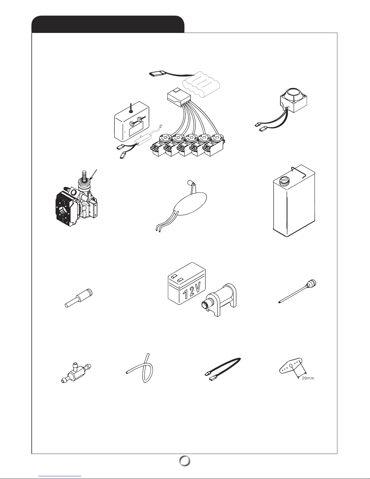
ITEMS NEED TO COMPLETE
Helicopter Fuel
(15%-30% Nitro)
6mm Hex Start Shaft
Cyclic/Collective
Servo Control
Horns
Servo Extensions
(2 each - 4” Long)
12” Fuel Tubing
(1/8” Silicone)
Fuel Filter
(3-way)
1.2V Ni-Start Battery12V Gell-Cell Battery
and Electric Starter
50-class Glo-Fuel Engine
Drive Washer Not Included
with model helicopter
Glo-Fuel Pump
6-channel - or greater
R/C Helicopter System
w/120o CCPM capabilities
Gyroscope
(x3)
4
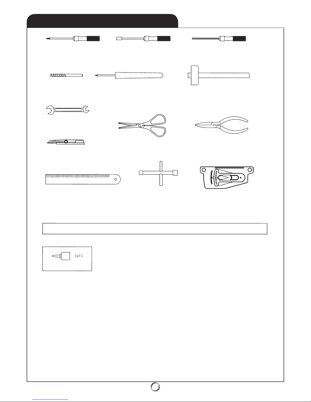
Phillips Screw Driver Nut Drivers (4mm/5.5mm/7mm) Allen Drivers (1.5mm/2mm/2.5mm/3mm)
Drill Bit 1/16” Auger - or - Reamer Small Hammer
Wrench (5.5mm/6mm)
Lexan Scissors Needle-nose Pliers
Hobby Knife
Ruler (metric) Greater Than 30cm 4-way Wrench (8-12mm)
Pitch Gauge
Thread Locker Is Used To Keep Assemblies Tight As Vibration May Cause Them To Loosen
Semi-permanent
BLUE Thread Locker
Due to the vibrations caused by operation, nuts, bolts, and set screws may have a tendency to loosen.
Repeated tightening is not the solution, instead, the careful application of thread locker is required.
Thread locker works something like a glue. There are various types of thread locker, from permanent
types which are usually RED in color, to semi-permanent types which are usually BLUE in color. BLUE
thread locker is what is recommended. Thread locker is not needed with nylon-lock nuts, nor where
metal screws thread into plastic. Finally, be careful to remove all traces of oil or grease by applying a
degreaser or acetone to bolts prior to assembly - clean with a paper towel until all traces are gone.
NOTE: Use care when using thread locker near bearing areas as
contamination may ruin the bearing and cause it to seize.
Never use thread locker on metal to plastic
Optional Tools and Accessories:
- Dial Indicator
- Ball Link Pliers
- Piston Locking Tool
- Calipers
- 10mm deep-well thin wall socket
- 2 ea. - 5/16” or 8mm 1/4” drive socket
- 2 ea. - 1/4” drive short extensions and 1/4” handles or drives
- one sheet of thin typing paper
TOOLS NEEDED FOR ASSEMBLY
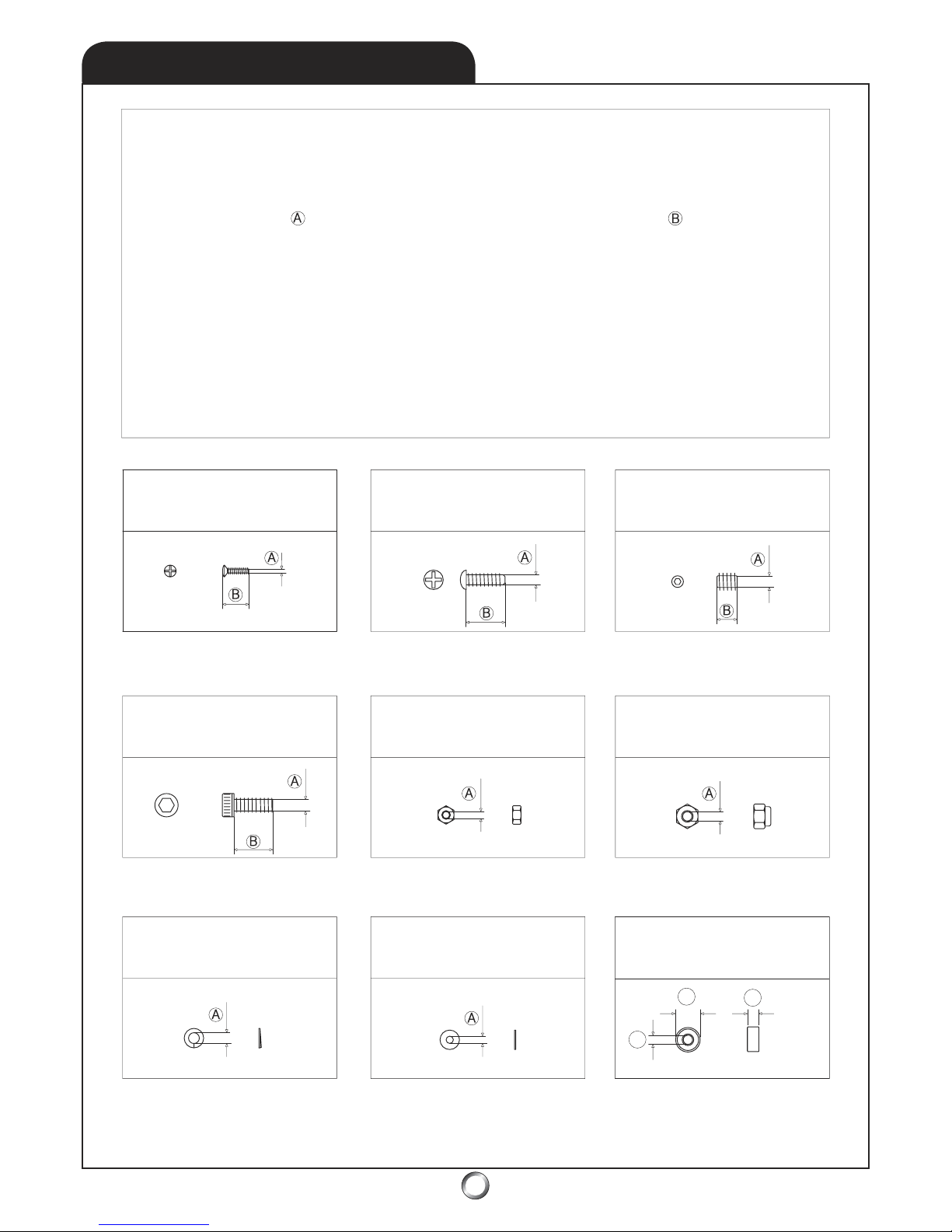
Various size nuts, bolts, set screws, and washers are used in the
Tiger 50 helicopter. Metric dimensions are given, first specifying
the diameter of the bolt or screw, then the length of the
bolt or screw. Washers and nuts are identified by the ID (inner
diameter) of the piece. Bearings are identified in order, by ID,
(inner diameter), then OD (outer diameter), then W (width).
Below are some examples of the types of hardware used.
M3mm Nylon Lock Nut
M2mm Hex Nut
M3x8mm Socket Head Bolt
M2x8mm Phillips Head Screw M2x8mm Self-tapping Screw M4x4mm Set Screw
M3mm Lock Washer M3mm Flat Washer
* NOTE: Do not use thread locker when a metal screw goes
into plastic as this may damage the plastic and cause failure.
Bearing L-1910ZZ
M10x19x7mm (ID, OD, W)
ID
OD W
HARDWARE IDENTIFICATION
5

1.1
CLUTCH BELL
6
1.2
TAIL DRIVE
* NOTE: Beveled side
faces belt-side of pulley.
* NOTE: Thoroughly clean the shaft-threads and the
hole-threads of any swarf (tiny metal shavings), before
applying thread locker to ensure precise alignment
between the pinion gear and clutch bell. Use special
care to prevent thread locker from entering the bearing!
10T Pinion Gear
1 : 8.9 Ratio
Clutch Bell Assembly
Bearing L-1910ZZ
* NOTE: Use a rocking
side-to-side motion to
slip bearing onto shaft.
* NOTE: Use a rotating
motion to twist the the clutch
bell assembly simultaneously.
M3x6mm Socket Head Bolt (x1)
M3mm Flat Washer (x1)
M3x6mm Scocket Head Bolt
M3mm Flat Washer
Front Tail Belt Pulley
Bearing R-1960ZZ
Tail Drive
Pinion Gear
Bearing R-1960ZZ
* NOTE: It can take several hours
for the thread locker to dry after
application - do not use assembly
until it’s completly set.
* NOTE: Use special
care to prevent thread
locker from entering
the bearings!
Bearing R-1960ZZ
M6x19x6mm (x2)
Bearing L-1910ZZ
M10x19x7mm
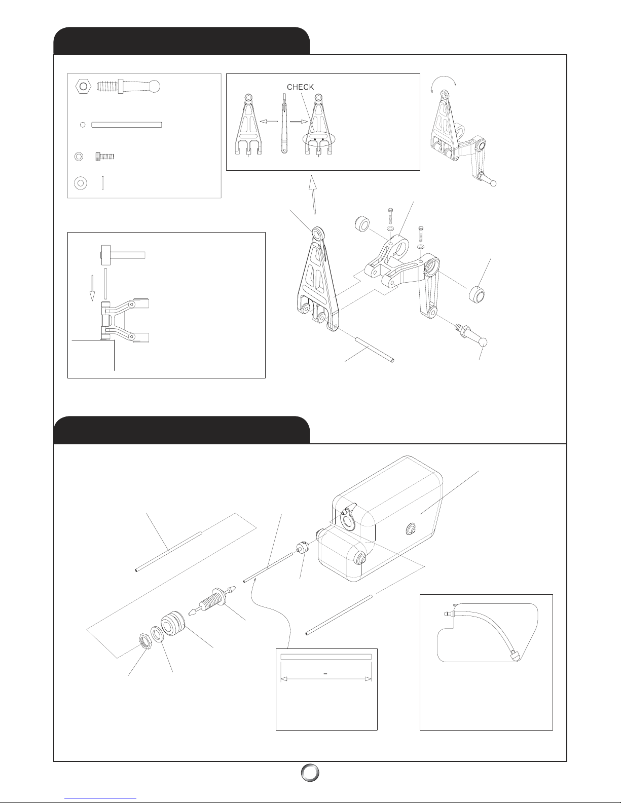
1.3
ELEVATOR LINK
7
1.4
FUEL TANK
14.5mm Long Ball Arm (x1)
Elevator Arm Pin (x1)
M2x10mm Socket
Head Bolt (x2)
M2mm Flat Washer (x2)
* NOTE: Mold marks
must face aft - toward
the swashplate ball.
Fore Aft
* VERIFY: swashplate
arm pivots freely on
the elevator arm.
Elevator Arm
Elevator Arm Bushing
AftFore
Swashplate Arm Link
14.5mm Long Ball Arm
Elevator Arm Pin
* NOTE: Use a small
hammer and tap gently
to drive the elevator arm
pin to join the swashplate
arm link to the elevator
arm. Ensure equal
amounts of pin protrude
on both sides of the
swashplate arm link.
Fuel Feed Line: 1/8” Silicone Fuel Tubing
(not included) - Du-Bro Medium (blue)
Silicone - No. 197 recommended.
* PRO TIP: For high nitro
use, replace the included
small diameter silicone fuel
pickup line with 1/8” ID
silicone fuel tubing.
Replace yearly!
Clunk Pickup
Muffler Pressure Line: 1/8” Silicone
Fuel Tubing (not included)
Inspect daily - replace yearly!
Fuel Tank - 14 oz
practical capacity
* NOTE: Ensure the clunk
swings freely by providing a
minimum 1/16” of clearance
from the aft fuel tank wall.
NutFlat Washer
Rubber Tank
Grommet
Feed Nipple
* NOTE: Fuel pickup
line length is critical,
measure carefully!
87mm 1mm
* PRO TIP: add a small dab of silicone RTV at
the four tank mounting points when you
assemble the fuel tank into the main frames.
+
* NOTE: Check fuel
tank for swarf before
assembling it!
8
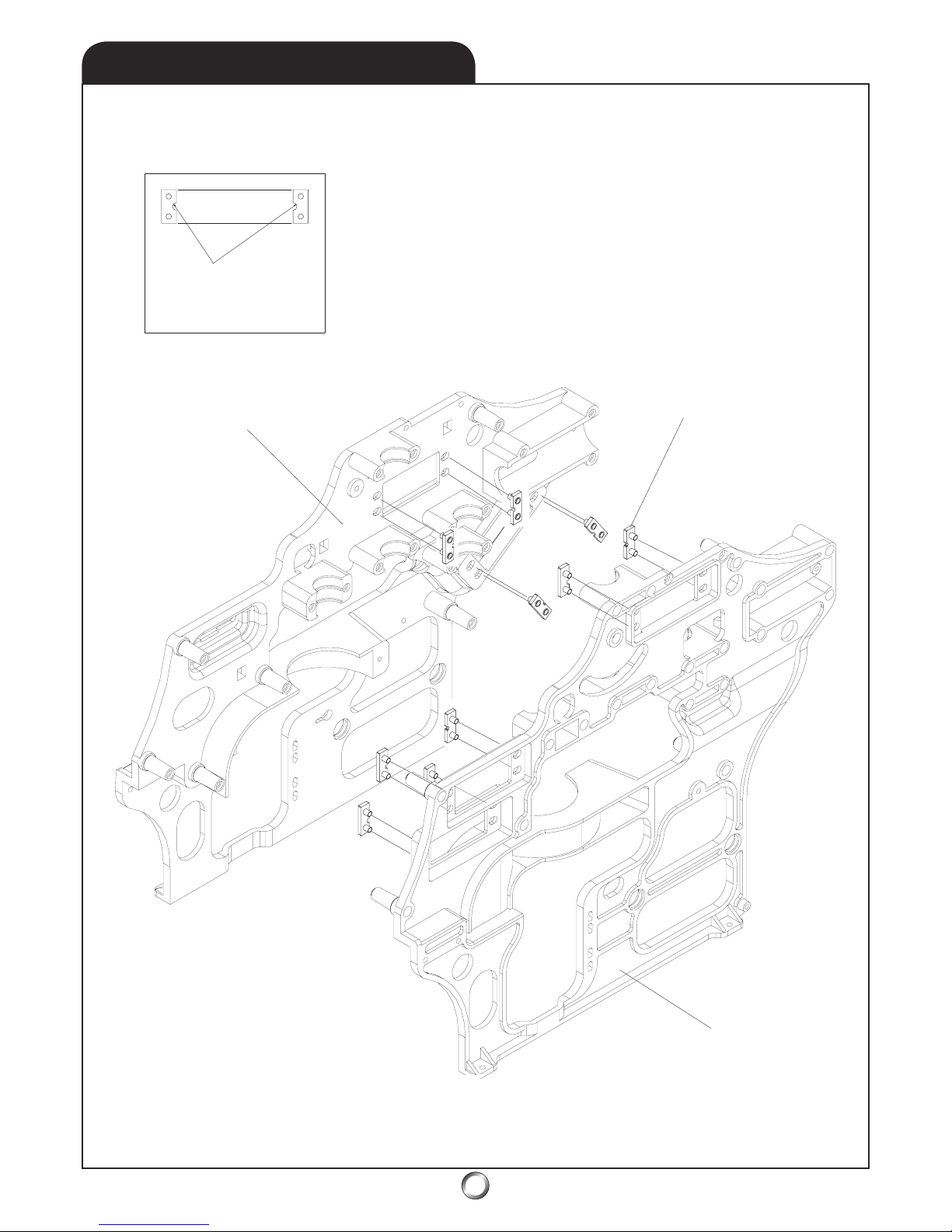
* NOTE: Notches
must face toward
each other!
Main Frame - Right
Main Frame - Left
Servo Mount Boss
* NOTE: Do not
glue the servo boss
plates into place!
2.1
SERVO-BOSS
9
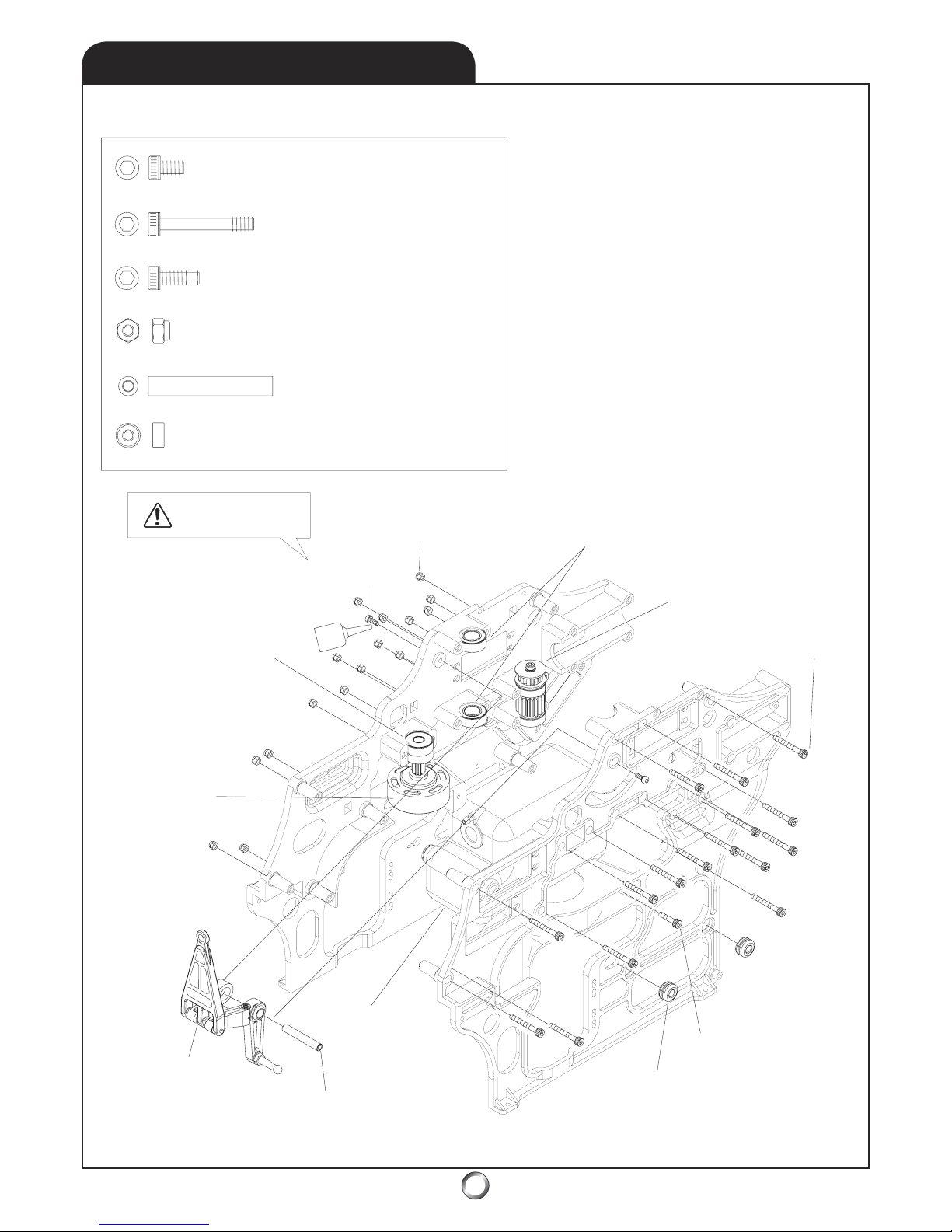
Elevator Arm Bushing 32mm (x1)
M3x8mm Socket Head Bolt (x2)
M3x38mm Socket Head Bolt (x16)
M3x12mm Socket Head Bolt (x1)
M3mm Nylon Lock Nut (x16)
Bearing L-1910ZZ (x2) - M10x19x7mm
Bearing L-1950ZZ (x1) - M5x19x6mm
Bearing L-1950ZZ (x1)
Bearing L-1910ZZ (x2)
M3mm Nylon Lock Nut
M3x8mm Socket Head Bolt (x2)
* NOTE: Use care
with thread locker!
Tail Drive Pinion Assembly
M3x38mm Socket
Head Bolt (x16)
(Step 1.2)
(Step 1.1)
(Step 1.3)
(Step 1.4)
Elevator Arm
Clutch Bell Assembly
M3x12mm Socket Head Bolt (x1)
Fuel Tank Rubber Grommet (x4)
Elevator Arm Bushing 32mm (x1)
Fuel Tank Assembly
* PRO TIP: add a small dab of
silicone RTV at the four fuel tank
mounting points when you
assemble the fuel tank assembly
into the main frame assembly.
2.2
MAIN FRAME

10
2.3
AVIONICS PLATFORMS
M3x10mm Socket head Bolt (x8)
Cabin Mount Stand-off 20mm (x2)
Cabin Mount Stand-off 10mm (x2)
M3x14 Set Screw (x2)
M3x12 Set Screw (x2)
Cabin Mount Stand-off
20mm (x2)
M3x14 Set
Screw (x2)
Gyroscope
Platform
M3x10mm Socket head Bolt (x8)
* NOTE: Don’t use
thread locker on
plastic parts!
Radio Platform
Cabin Mount Stand-off
10mm (x2)
M3x12 Set Screw (x2)
Use thread locker on
set screw, install it
evenly into standoff
and let it dry before
assembly to frame.
Indice


