AudioArts Engineering AIR 1 Guida rapida

Technical Guide
December 2007
AIR 1
R
ADIO
M
IXING
C
ONSOLE

page 2
AIR 1 / Dec 2007
CONSOLE FEATURES
Console Features
Overview
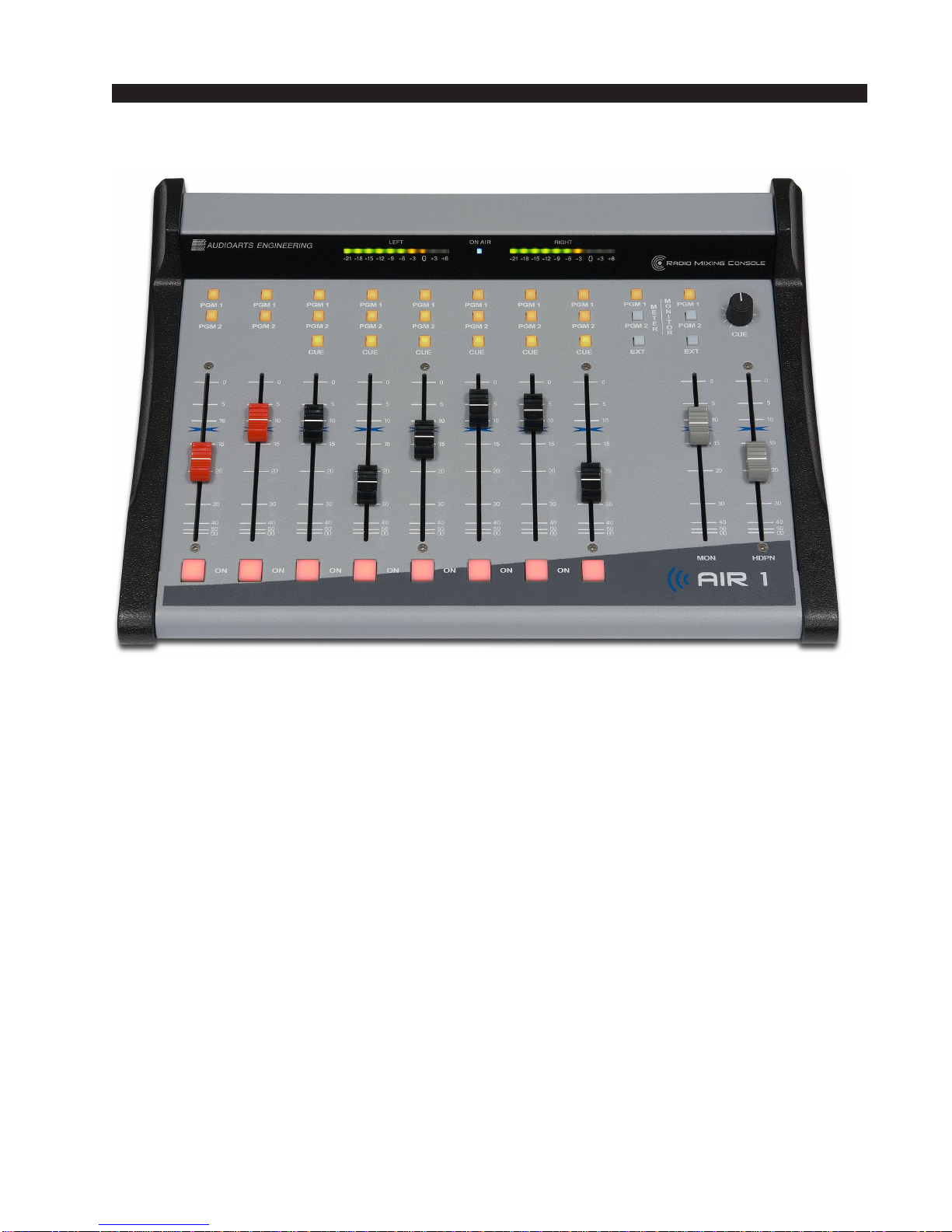
TheAIR1consoleconsistsofaninputsectionwitheightfadersandassociated
switches,monitorandheadphonesectionwithtwofadersandassociatedswitches.
Thebasic purposeof theconsole isto takesome ofthe manyaudio signalsthat
are wired to the console inputs, and generate several outputs that combine these
inputsinvariousgroupsandatvariousdegreesofloudness,orsignalstrength.The
typicalapplicationisinaradiostationwhereitisdesiredtodevelopthesignalsthat
the station will broadcast (the on air signal), as well as several additional signals
for recording and monitoring.
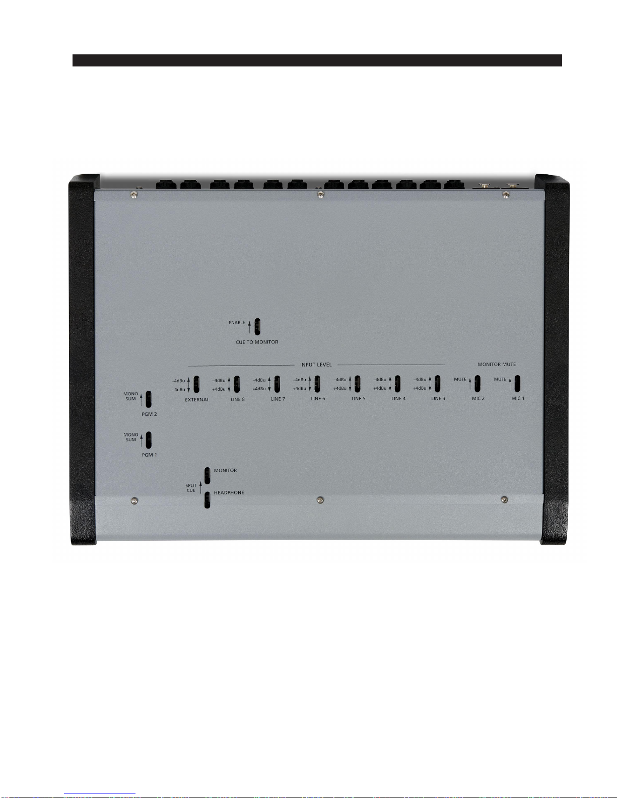
Allprogrammingis madeviaPCB mounted slideswitchesaccessible through
openings in the console’s bottom panel.

page 3
AIR 1 / Dec 2007
CONSOLE FEATURES
AIR 1 Bottom Panel

page 4
AIR 1 / Dec 2007
CONSOLE FEATURES
Inputs
TheAIR1consoleisdesignedtohandle6analogstereo(+4dBubalanced)
inputs, two mono microphone (-50dBu balanced) inputs, and one external
stereo line level (+4dBu balanced) input that goes directly to control room or
meter.
Analog Mono Mic Level Inputs
These inputs are used to connect to microphones, which typically put out
signals at relatively low signal strength, and therefore require more amplifi-
cation (increase in signal strength) to be properly audible in the output. Mic
level sources are wired to female XLR connectors located on the rear of the
console. These mic inputs feed the console’s first two faders.
Example: with a microphone input of –60dBm @150 ohm at the port,
gain trim can set levels from -22dBu to +16dBu (note maximum preamp
gain is +76dB) at the PGM 1 or PGM 2 output.
Analog Stereo Line Level Inputs
Theseinputsaretypicallyusedtoconnecttomachines,suchastapedecks,
cartmachines,CD players,etc.,thatprovideanalogoutputs.Allsixinputline
levelsignalsandexternalsignalareswitchablebetween-4dBuand+4dBuvia
slide switches, LINE 3 - LINE 8 (SW 8 - SW 3 on MBA1-1 PCB) and
EXTERNAL (SW 2 on MBA1-1 PCB), accessible through openings in the
console’s bottom panel.
When UP the input level signal is -4dBu;
When DOWN the input level signal is +4dBu.

page 5
AIR 1 / Dec 2007
CONSOLE FEATURES
Outputs
Theconsoleoutputsincludetwoprogramstereobusses(PGM1andPGM2),
a stereo monitor output, a mono cue output, and a stereo headphone jack.
The console’s mono cue signal is provided to drive an external powered
speaker,oramplifier and speaker combination,andalso provides the cuesignal
usedtointerruptmonitor and headphones, ifsuchinterrupt has been enabled by
the installer.
Program Outputs
The console’s main analog outputs are the two Program stereo buses
(PGM 1 and PGM 2). The Program stereo outputs can be programmed to
monooutputsviaslideswitches,PGM1MONOSUMandPGM2MONO
SUM (SW 11 and SW 12 on MBA1-1 PCB).
WhenSW12 is UPthePGM 1 is inmonomode, which sumstheleft
and right PGM 1 channels and sends this mono signal to both left and
right channels of the PGM 1 output.
When SW 12 is DOWN the PGM 1 is in stereo mode.
WhenSW11 is UPthePGM 2 is inmonomode, which sumstheleft
and right PGM 2 channels and sends this mono signal to both left and
right channels of the PGM 2 output.
When SW 11 is DOWN the PGM 2 is in stereo mode.
Monitor Output
TheAIR1hasaMONITORoutputdesignedtodriveastereopairofpowered
speakers,orastereoamplifierdrivingseparatespeakers,toallowtheoperatorto
listen to either PGM 1 or PGM 2, or an external signal. The console
may be programmed to mute the monitor or to provide monitor and
headphone split cue.
Cue to Monitor
TheCUETO MONITOR (SW1on MBA1-1 PCB)slideswitch,
when activated (UP), sends cue to the monitor.

page 6
AIR 1 / Dec 2007
CONSOLE FEATURES
Split Cue, Monitor
TheMONITORSPLITCUE(SW3onMBA1-1PCB)slide
switch,whenactivated(UP),allowsasummed(L+R)versionof
the regular program to be sent to the right side of the monitor
stereo output, while CUE is sent to the left side.
Split Cue, Headphone
For headphones, consoles are normally programmed at the
factory for CUE to appear on the left channel, while the L+R
sum of the monitor output appears on the right. This can be
changedwith theHEADPHONE SPLITCUE (SW4 onMBA1-1 PCB)slide switch.
Todefeatthissplitcueoption,turntheswitch off(DOWN).With thissettingcuewill
interrupt both sides of the headphones.
Monitor Mute
The console has the ability to mute the monitor output.
Theconsole alsohasanONAIRtallyoutput thatisusedto
drive user-provided external circuitry that will in turn
operate the ON AIR indicator. This tally is automatically
activated whenever the monitor mute is activated.
The two microphone channels can be programmed via
MIC1andMIC2(SW9andSW10onMBA1-1PCB)slide
switchestomute themonitor speakers whenthe channelis
ON. When MIC 1, SW 10, is UP the console’s monitor speakers are automatically
muted when the MIC 1 channel is turned ON.
When MIC 2, SW 9, is UP the console’s monitor speakers are automatically
muted when the MIC 2 channel is turned ON.
Thisisdonetopreventfeedbackfromthemonitorspeakertotheannouncer’smic.
At the same time that muting is enabled (by turning on either of the two MIC
channelswhenset toactivatethemonitormute),theONAIRLEDinthecenterofthe
meterbridge is also turned on, and a closure is provided at the TALLY output to
activate the external circuitry for the ON AIR indicator.

page 7
AIR 1 / Dec 2007
CONSOLE FEATURES
On Air Tally
Forcontrollinganexternal“on-air”indicator,arelayisprovided.Thetally
is activated when a mic channel set for monitor mute is turned on.
The relay connections are available at the “TALLY” TRS connector
mountedontherearoftheconsole.Connecttheon-airlighttotheexternaluser-
provided relay. Do not bring on-air light AC connections to any pin of any
connector on the console.
"TALLY" TRS
CONNECTOR PIN YOUR
POWER
SUPPLY
–
TYPICAL MONITOR ON-AIR TALLY CIRCUI
T
USER-SUPPLIED RELAY TRIGGERED BY CONSOLE MONITOR MUTE CIRCUI
T
+
INTERNAL AIR
TALLY RELAY
COM
+
–
1N4002
ECG
B40240
or equiv.
relay
RELAY CIRCUIT POWERED BY USE
R
SUPPLIED EXTERNAL SUPPLY
N.O.
N.C.
2A
max
30VDC PIN
R
PIN
T

page 8
AIR 1 / Dec 2007
CONTROLS AND FUNCTIONS
Controls and Functions
Input Section
The AIR 1 Input section consist of two mono microphone input channels and
six stereo analog input channels.
TheMICandLINEinputchannelshavethesamecontrols,exceptthattheMIC
channels don’t have a CUE switch.

page 9
AIR 1 / Dec 2007
CONTROLS AND FUNCTIONS
Source
TheAIR1consoleacceptstwomonomicinputsignalsviafemaleXLR
and six stereo line level input signals via TRS connectors.
MIC 1 and MIC 2 GAIN trimpots at the rear of the console below the
MICinput XLRconnectorsareusedtoadjustthe gainofeachmicrophone
inputindependently.Thesearenormally“setandforget”adjustments,and
aresetatthefactoryforagainof54dB,thusbringinga-50dBumicrophone
input level up to +4dBu at the output.
Ifyouhavemorethantwomicrophonesinuse,youwillneedtoprovide
externalmicpreampsforallbuttwoofthem.Theseadditionalmicswillnot
be able to activate the muting and on air tally functions.
Program Assign
Outputswitchesassigntheselectedsourcesignaltoanycombinationof
theconsole’stwostereoProgramoutputs—PGM1andPGM2.Thebutton
willbelitwhenthesourceisassigntoitsrespectivebus.Toremoveasource
fromthebus,pressthebuttonagain;thelightwillgoofftoindicatethatthe
source is no longer assigned to that bus. NOTE that when the console is
powered up all input channels will be off and assigned to PGM 1.
Cue Button
TheCUEswitch (notfound on theMIC channels)placesthe channel’s
signal on the console’s cue bus, where it may be heard in the external cue
speaker, as an interrupt to the console operator’s headphones, and as an
interrupt to the monitor speakers, if so programmed.
PresstheCUEbutton.Thechannel’sinputsignalwillbeincludedinthe
console’sCUEoutput at alevelthat is independent oftheFADER setting,
and the button will light. The fader does not need to be turned ON. To
remove a fader from cue, press the CUE BUTTON again; the light will go
off to indicate the channel is no longer assigned to cue.
Fader
Level is set by a long-throw fader. The fader is the sliding mechanism
that determines how strong is the presence of the input in some of the
various console outputs.
If the fader is all the way down (that is, pulled toward the console
operator), the signal will not be present in either of the two program main
busestowhichitisassigned.Asthefaderismovedup(thatis,pushedaway
from the console operator) the signal will appear more strongly in each of
the main buses to which it is assigned.
ON Button
The ON button turns the channel on and off by means of electronic
switching. The channel is on when the ON button is lit. The mic channels
canalso beprogrammed(asmentionedintheprevious chapter)toactivate
monitor mute and on air tally.

page 10
AIR 1 / Dec 2007
CONTROLS AND FUNCTIONS
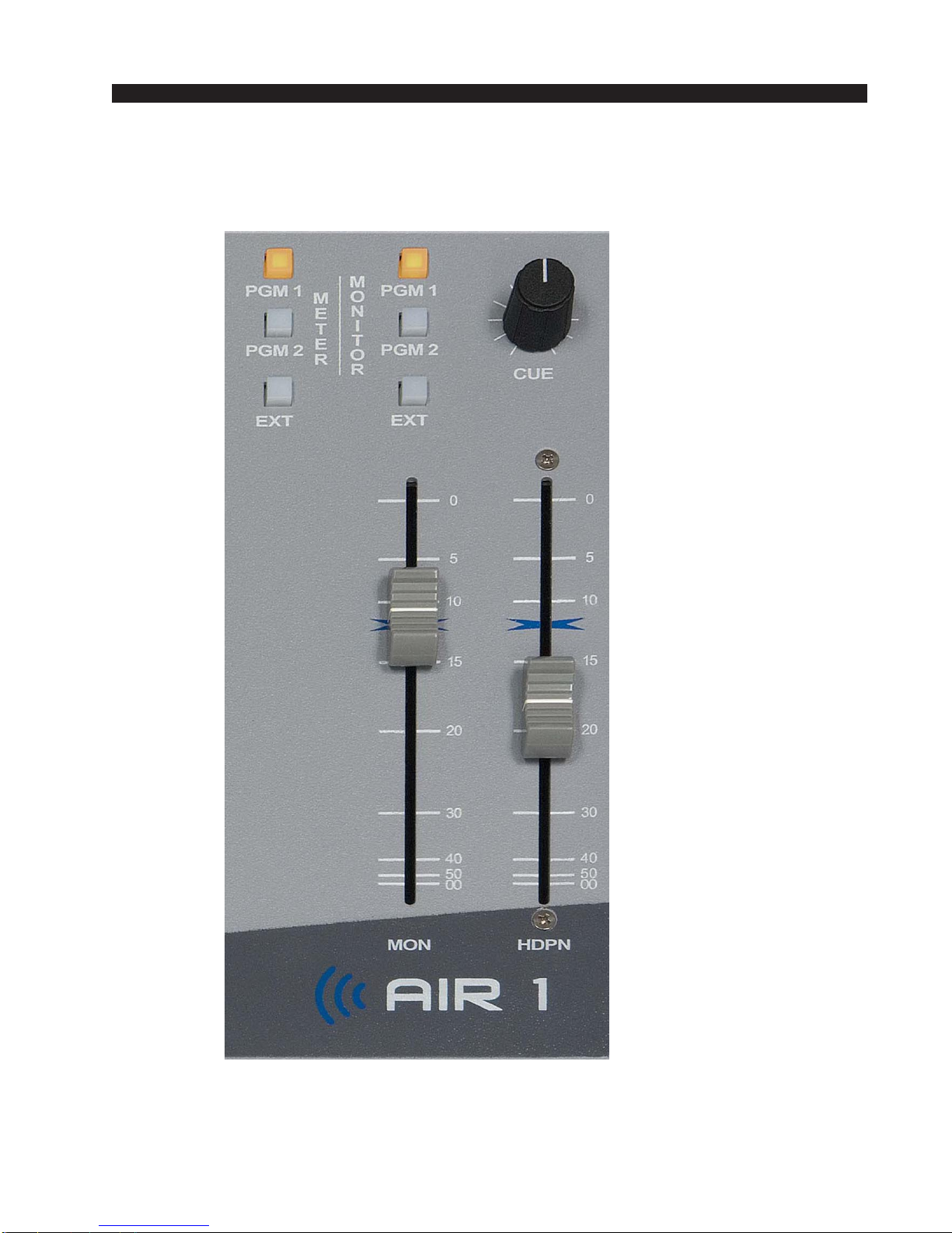
Master Section
The Master section includes the monitor, headphone, and meters controls.
Altri manuali per AIR 1
2
Indice
Altri manuali AudioArts Engineering Mixer musicale

AudioArts Engineering
AudioArts Engineering Audioarts 08 Manuale utente

AudioArts Engineering
AudioArts Engineering AIR 1 Manuale utente

AudioArts Engineering
AudioArts Engineering AIR 2+ Manuale utente

AudioArts Engineering
AudioArts Engineering Lightning Manuale utente

AudioArts Engineering
AudioArts Engineering DMX-8 Istruzioni per il montaggio

AudioArts Engineering
AudioArts Engineering audio console r-55e Manuale utente

AudioArts Engineering
AudioArts Engineering AIR 1 Manuale utente