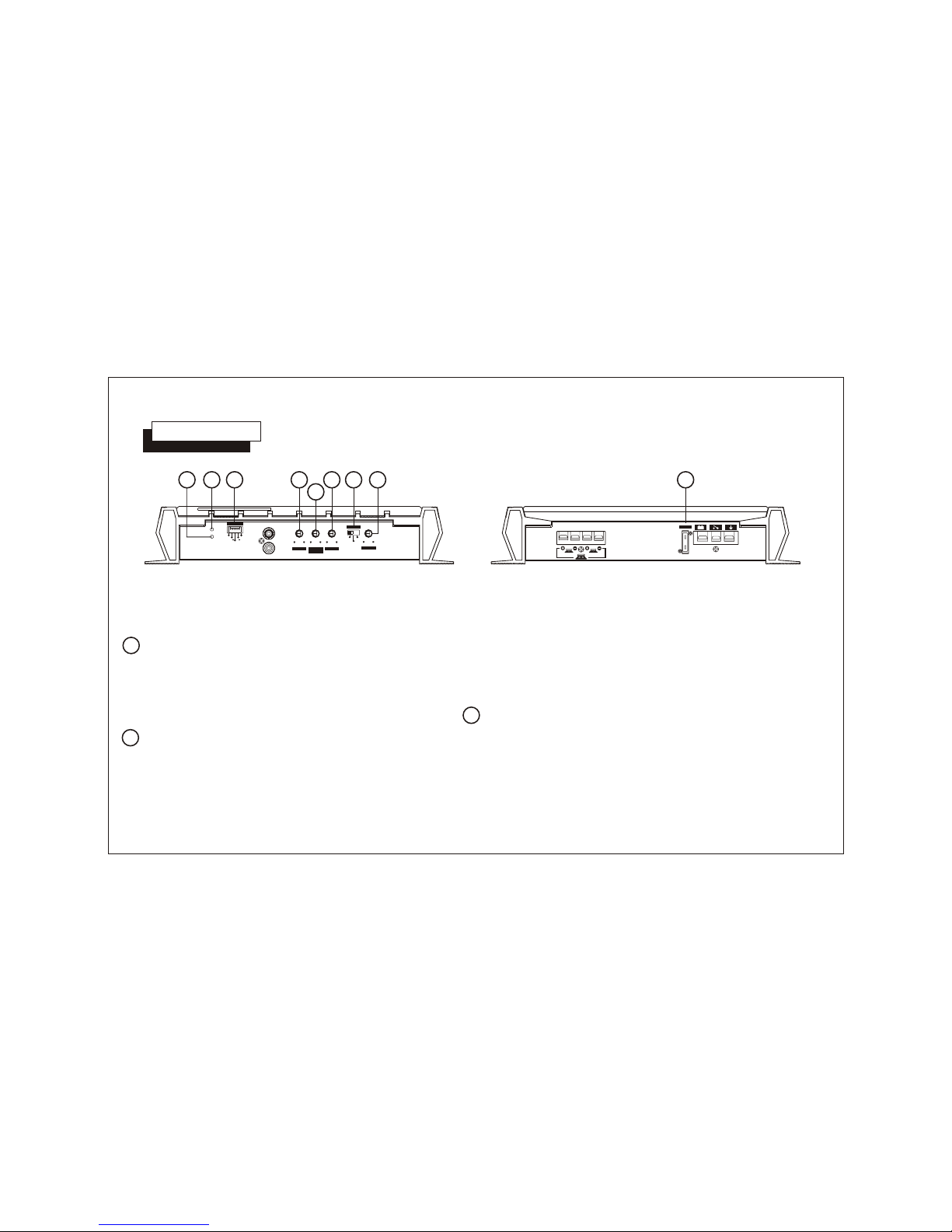
Audiovox AXT-800 Manuale utente

OWNER'S
MANUAL
Model AXT-800
800 Watt Bridgeable
2-Channel
MOSFET Amplifier

INDEX
Specifications.....................................................................3
Precautions........................................................................4
Installation Instructions...................................................... 5
Wiring Instructions........................................................ 6 - 7
Input Wiring Diagram......................................................... 8
Output Wiring Diagram...................................................... 9
Operation.................................................................. 10 - 12
Warranty...........................................................................13

Input Impedance: Low-Level 10K Ohms
High-Level 100 Ohms
Input Sensitivity: Low-Level 200 mV - 8 V
High-Level 2V - 10 V
Filter type: Selectable High/Full/Low-pass
Crossover @ 12dB/Octave
Filter Crossover: LPF 50-250 Hz (variable)
HPF 50-250 Hz (variable)
Supply Voltage: 12 volts, negative ground
Fuse Rating: 20 amps.
Dimensions (W X H X D): 295 mm X 54.3 mm X 300.3 mm
11-5/8" X 2-1/8" X 11-7/8"
Maximum Output Power: 800 Watts
200 Watts RMS x 2
@ 4 Ohms
Output Impedance: 2 - 8 Ohms (stereo)
Frequency Response: 10 - 35KHz +/-1 dB
Channel Separation: 60 dB
Signal / Noise Ratio: 90 dB
HIGH PERFORMANCE STEREO AMPLIFIER
SPECIFICATIONS
* Due to continuing improvement, Audiovox reserves the right to change features and design without notice.
-3-
This power amplifier has been designed to provide high Quality performance with a
minimum of maintenance. However, it's performance will only be as good as the care
and quality of components with which it is installed. We therefore advise that you
read these instructions very carefully to familiarize yourself with the product and it's
features.
Should you require assistance with the installation or wiring so this unit, please call
our toll-free "HELP" line at 1-800-645-4994 during the days/hours shown.
HELP!
1-800-645-4994
Monday-Friday 8:30am - 7:00pm Eastern
Saturday 9:00am - 5:00pm Eastern

1. Although this unit is designed with built-in self-protection circuits, there may be a possibility of damage if it is not wired
correctly. Please follow the wiring instructions carefully for the type of system being used.
2. The last lead to be connected is the wire to the positive( ) terminal of the battery. Connect this wire only after having
completed and checked all other connections to the amplifier.
3. By nature of its design, a power amplifier generates heat and requires good air circulation around it to dissipate that
heat. Do not install the amplifier in an enclosed area which does not permit adequate air circulation. Should the
temperature of the unit rise too high, the internal thermal sensors will shut off operation until it has cooled down
sufficiently.
4. If fuse replacement is necessary, use only fuses of the same ampere rating as originally supplied with the unit. The
use of fuses with incorrect ratings may cause serious damage to the amplifier. If fuses blow consistently, carefully
check all electrical connections to the unit.
5. Supply of adequate battery voltage is critical to the proper operation of the power amplifier. The leads to the battery
and chassis ground must be of a thick enough gauge to provide this voltage to the amplifier. We recommend #10 gauge
wire or thicker (smaller gauge #) for the battery and ground leads.
6. Make certain that the speaker(s) to be used with this amplifier are capable of handing the output power (wattage) of
the unit. Use of speaker(s) not rated for the output of this amplifier may cause damage to or failure of the speaker(s)
for which Audiovox will not be liable.
-4-
PRECAUTIONS
++

1. Select a mounting area where the amplifier will
have sufficient air circulation for proper cooling.
Inadequate air circulation will cause the temperature
of the amplifier to rise and will trigger the thermal
protection mode.
2. Place the amplifier on the mounting surface and
mark the locations of the four mounting holes as
shown in the illustration.
3. Remove the amplifier and drill a 1/8" hole at
each of the four locations.
CAUTION: Before drilling the holes, look at the
underside of the mounting surface. Always check
carefully to avoid drilling into wiring, braces, fuel
or brake lines.
CHECK BEFORE YOU DRILL!
4. Secure the amplifier to the mounting surface using
The self-tapping screws provided.
-5-
INSTALLATION INSTRUCTIONS
INSTALLATION DIAGRAM

The wiring of your amplifier will depend on the system and speakers you are using but will either be a stereo, mono, or
mixed-mono application. The following pages illustrate the input and output wiring for these types. please refer to the
appropriate diagrams for the system configuration you are using. The power and speakers wire connections for this amplifier
are made via screw tightened terminal blocks. Loosen the screw for the connection to be made and fully insert the wire
(strip 1/2" of insulation from the end) under the respective screw on the side panel (crimp-on "U" terminals are provided
to simplify wiring and we recommend their use.). Tighten the screw down to secure the wire.
1. Power Connection
The battery terminal (BATT) must be connected directly to the positive terminal of the vehicle battery to provide an
adequate voltage source and minimize noise. Connecting the battery terminal lead to any other point (such as the fuse
block) will reduce the power output and may cause noise and distortion. Use only #10 gauge or thicker (smaller gauge
#) wire for this lead and connect it to the terminal of the battery after all other wiring is completed.
2. Ground Connection
The ground terminal (GND) connection is also critical to the correct operation of the amplifier. Use a wire of the same
gauge as the power connection (#10 or thicker) and connect it between the ground terminal (GND) of the amplifier and
a metal part of the vehicle close to the mounting location. This wire should be as short as possible and any paint or rust
at the grounding point should be scraped away to provide a clean metal surface to which the end of the ground wire can
be screwed or bolted.
3. Remote Turn-On Connection
The amplifier is turned on by applying +12 volts to the remote turn-on terminal (REM). The wire lead to this terminal
should be connected to the "Auto-Antenna" lead from the car stereo which will provide the +12 volts only when the car
stereo is turned on. If the car stereo does not provide an Auto-Antenna lead, the remote turn-on lead may be wired to
an "Accessory" or "Radio" terminal in the car's fuse block. This will turn the amplifier on and off with the ignition key,
regardless of whether the car stereo is on or off. The remote turn-on lead does not carry large currents, so #20 gauge
wire may be used for this application.
#10
#10
-6-
WIRING INSTRUCTIONS

4. Speaker Connections
Depending on the type and number of speakers used with the amplifier, wire them to the speaker terminals as per the
appropriate wiring diagram. For most applications, #18 gauge wire should be used for the speaker leads but in no case
thinner than #20 gauge. For leads in excess of 10 feet, #16 gauge is recommended. When wiring the speakers, pay
careful attention to the polarity of the terminals on the speakers and make certain they correspond to the polarity of the
corresponding terminals on the amplifier. DO NOT ground any speaker leads to the chassis of the vehicle.
5. Input Connections
This amplifier features both high and low-level input capability. Use either the low-level or high-level inputs, not both.
If low-level outputs are provided from the car stereo, it is recommended that the low-level inputs be used for lowest
distortion and best performance. Use good quality shielded audio cables with RCA plugs at both ends to connect
the stereo to the amplifier and keep the cable lengths to a minimum to avoid noise.
If the car stereo does not provide low-level outputs, the amplifier may be connected via the speaker (high-level)
outputs from the stereo. Wire the speaker leads from the car stereo to the 5-pin adaptor harnesses as shown in the
diagram (shielded cable is not required for this application) and plug the connectors into the mating High-Level Input
socket on the amplifier. Carefully splice and insulate all wire connections.
CAUTION: Use either the low-level or the high-level inputs on the amplifier.
DO NOT use both input levels at the same time.
-7-
WIRING INSTRUCTIONS

-8-
USE EITHER HIGH-LEVEL OR
LOW-LEVEL INPUT, NOT BOTH.
IMPORTANT
RCA TYPE
SHIELED CABLES
(NOT INCLUDED)
Right Speaker
CAR STEREO
INPUT WIRING DIAGRAM
White
Green
Black
Brown
Gray
Left Speaker
CHASSIS GROUND ON RADIO
NOTE:
When using High-Level (Speaker) Outputs
of car stereo, connect only the Positive (+)
wires to the amplifier. Do not use Negative (-)
Output wires (insulate ends with tape and
leave disconnected)
HI-INPUTHI-INPUT
GNDGND
L +L + R +R +
LLRR
RR
LL
PWRPWR
PRTPRT
MINMIN MAXMAX
GAINGAIN
0dB0dB 18dB18dB 50Hz50Hz 250Hz250Hz
LPFLPF
50Hz50Hz 250Hz250Hz
HPFHPF
X-OVERX-OVER
HPFHPF
LPFLPF
FULLFULL
BASS
BOOST
BASS
BOOST
LOW LEVEL INPUTS
HIGH LEVEL (SPEAKER) INPUTS
(WIRESIDE VIEW)

-9-
CAR STEREO
GROUND
BATTERY
FOR 12 VOLT USE ONLY AUTO-ANTENNA LEAD
GROUND METAL
SECTION OF VEHICLE
EXISTING SCREW OR BOLT CLEAN PAINT, RUST, DIRT
OR GREASE FROM AREA FOR GOOD CONNECTION.
RIGHT SPEAKER
2- 8 OHM
LEFT SPEAKER
2-8 OHM
OUTPUT WIRING DIAGRAM
LEFT RIGHT
REMBATT GND
FUSEFUSE
BRIDGEDBRIDGED

-10-
312 5
OPERATION
46
HI-INPUTHI-INPUT
GNDGND
L +L + R +R+
LLRR
RR
LL
PWRPWR
PRTPRT
MINMIN MAXMAX
GAINGAIN
0dB0dB 18dB18dB 50Hz50Hz 250Hz250Hz
LPFLPF
50Hz50Hz 250Hz250Hz
HPFHPF
X-OVERX-OVER
HPFHPF
LPFLPF
FULLFULL
BASS
BOOST
BASS
BOOST
LEFT RIGHT
REMREMBATTBATT GNDGND
FUSEFUSE
BRIDGEDBRIDGED
7
8 9
Power Indicator Lamps
After initial set-up, the amplifier should not require any
further adjustment unless there is a change in the car
stereo or speaker system with which it is used.
If activated by a rise in emperature, the unit will resume
operation after cooling off to a normal operating range.
If activated by an overload condition, the source of the
overload must be found and corrected to resume
operation of the amplifier.
Most overload conditions are caused by mis-wiring or
operation into incorrect speaker loads. Re-check all
wiring and connections if this situation occurs and
correct as necessary.
2
1
The Power Indicator Lamps will light to indicate that the unit
is connected to the battery and that the Remote
Turn-On terminal is receiving +12 volts, thus turning on the
amplifier.
Protection Mode LED
This LED illuminates red to indicate that the self-protection
circuits have been activated and have shutoff operation of
the amplifier. The protection circuits may be triggered
by the temperature of the unit rising above a safe level
or by an overload condition.
Level (Gain) Controls
The amplifier is capable of operating from sources
supplying a wide range of input levels. The Level controls
should initially be set to the mid-rotation position.
If it is found that there is not enough output even when
the volume control on the car stereo is at its maximum
setting, adjust the Level control to increase the output
from the system.
3
Altri manuali per AXT-800
1
Indice
Altri manuali Audiovox Amplificatore per auto


