Auto Crane AC30A Manuale utente

AC30A
COMPRESSOR
OWNERS MANUAL
Rev. 03/15/2011
Serial No. __________________
Mailing Address:
P.O. Box 580697
Tulsa, OK 74158-0697
Physical Address:
4707 N. Mingo Rd.
Tulsa, OK 74117-5904 Phone (918) 836-0463
Manual No. AC30A Fax (918) 834-5979
Rev. 07/08/2008 http://www.autocrane.com

To: Fax:
From: Date:
Re: Pages:
Name: Phone:
Address:
City: State: Zip:
Contact:
Name:
Address:
City: State: Zip:
Contact:
VIN #
ONE REGISTRATION FORM PER UNIT (CRANE OR BODY)
Registration form must be mailed or faxed within 15 days of customer installation.
Mail to:
Warranty Department
Auto Crane Company
P.O. Box 581510
Tulsa, OK 74158-0697
Date Product Delivered: Date Processed:*
* For Auto Crane use only
Product Information:
(Required for Warranty Activation)
Model No.: Serial No.:
E-mail Address:
Distributor Information:
(Required for Warranty Activation)
Product Registration
E-mail Address:
(Required for Warranty Activation)
Auto Crane Warranty Registration
(918) 834-5979Warranty Department
End User Information:
Fax Transmission
Warranty Registration Rev. 050905

10/09
Rev Date Section(s)OrPage(s) Description of Change
09/02/03 Last page New 2-year warranty policy to replace 1-year warranty
policy
05/09/05 2nd Quarter New Revisions
11/28/05 3-1.0.0 Updated for new hydraulic motor
06/10/06 Updated for new machine design.
07/12/07 Bill of Materials Audit
08/13/07 Updated Drawing
11/28/11 Updated Drawing 200280-999
AC30A
OWNER’S MANUAL – REVISION RECORD

10/09
WARNINGS
READ THIS PAGE
WARNING! Federal law (49 cfr part 571) requires that the Final Stage Manufacturer of a vehicle
certify that the vehicle complies with all applicable federal regulations. Any modifications performed
on the vehicle prior to the final state are also considered intermediate stage manufacturing and must
be certified as to compliance. The installer of this crane and body is considered on of the
manufacturers of the vehicle. As such a manufacturer, the installer is responsible for compliance
with all applicable federal and state regulations, and is required to certify that the vehicle is in
compliance.
WARNING! It is the further responsibility of the installer to comply with the OSHA Truck Crane
Stability Requirements as specified by 29 CFR part 1910.180 (C) (1).
WARNING! NEVER OPERATE THE CRANE NEAR ELECTRICAL POWER LINES!
Death or serious injury will result from boom, line, or load contacting electric lines. Do not use crane
within 10 feet (3.05m) of electric power lines carrying up to 50,000 volts. One foot additional
clearance is required for every additional 30,000 volts or less. SEE DANGER DECAL (P/N 040529)
in this Owner's Manual.
WARNING! NEVER.........................................
i EXCEED load chart capacities (centerline of rotation to hoist hook).
i Un-reel last 5 wraps of cable from drum!
i Wrap cable around load!
i Attempt to lift or drag a load from the side! The boom can fail far below its rated capacity.
i Weld, modify, or use unauthorized components on any Auto Crane unit! This will void any
warranty or liability. Also failure of the crane may result.
i Place a chain link on the tip of the hook and try to lift a load!
i Use a sling bar or anything larger than the hook throat that could prevent the hook latch from
closing, thus negating the safety feature!
i Hold on any pendant Select Switch that will cause unsafe operating conditions!
WARNING! In using a hook with latch, ALWAYS make sure that the hook throat is closed before
lifting a load! Proper attention and common sense applied to the use of the hoist hook and various
slings will prevent possible damage to material being hoisted and may prevent injury to personnel.
WARNING! Failure to correctly plumb and wire crane can cause inadvertent operation and damage
to crane and/or personnel!
WARNING! Auto Crane Company remote controlled cranes are not designed or intended to be
used for any applications involving the lifting or moving of personnel.
WARNING! ALWAYS operate the crane in compliance with the load capacity chart. DO NOT USE
the overload shutdown device to determine maximum rated loads, if the crane is equipped with this
type of device.

10/09
SPECIFICATIONS.............................................................................. 1-1.0.0
GENERAL DIMENSIONS................................................................... 1-2.0.0
INSTALLATION INSTRUCTIONS....................................................... 1-3.0.0
OPERATION....................................................................................... 1-4.0.0
SPARE PARTS LIST........................................................................... 1-6.0.0
HYDRAULIC INSTALLATION............................................................. 2-1.0.0
PNEUMATIC SCHEMATIC................................................................. 2-2.0.0
ELECTICAL SYSTEM......................................................................... 2-3.0.0
HYDRAULIC SCHEMATIC.................................................................. 2-4.0.0
GENERAL ASSEMBLY........................................................................ 3-1.0.0
MAINTENANCE.................................................................................. 4-1.0.0
TROUBLESHOOTING......................................................................... 4-2.0.0
RECEIVER TANK................................................................................ 5-1.0.0
FILTER/REGULATOR/LUBRICATOR..................................................6-1.1.0
MISC....................................................................................................7-1.0.0
WARRANTY............................................................................................ LAST PAGE
AC30A HYDRAULIC AIR COMPRESSOR
OWNER’S MANUAL
TABLE OF CONTENTS

10/09
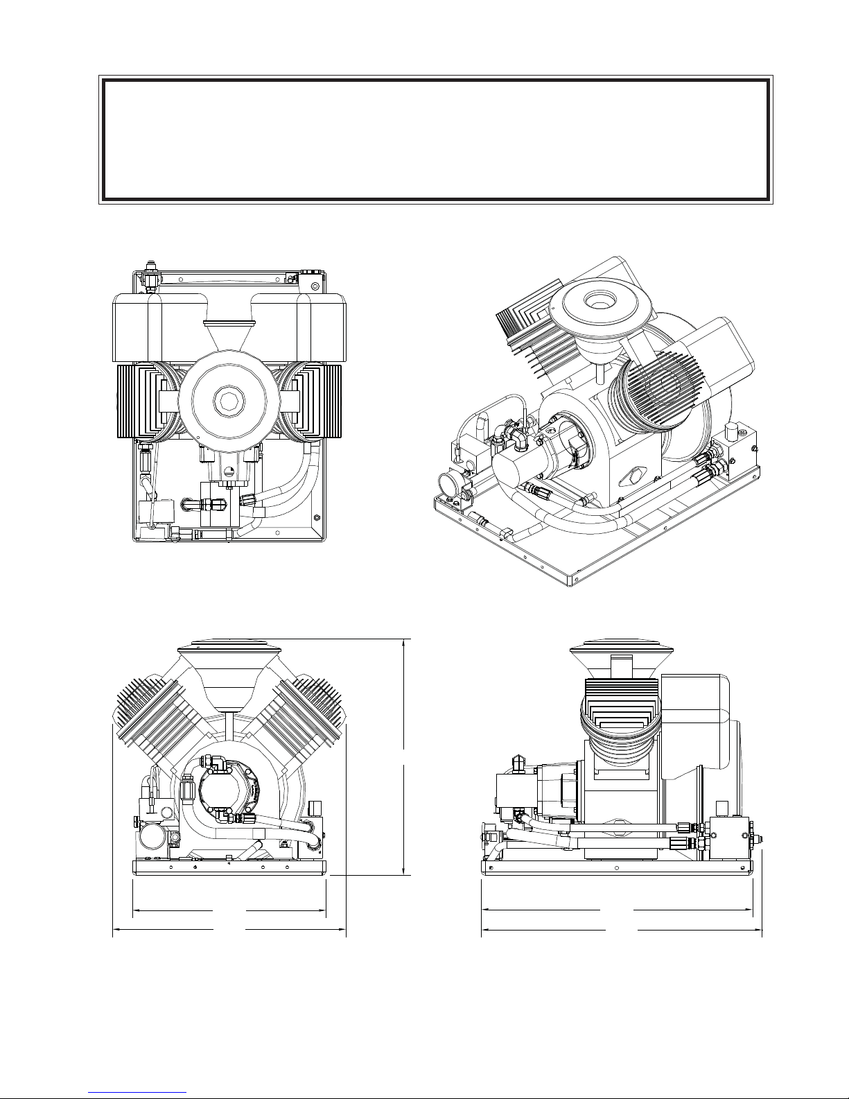
Dimensions
Width: 25.0 in. (AT TOP)
20.0 in. (AT BASE)
Height: 24.5 in.
Length: 28.25 in.
Weight: 250 lbs. w/cage
Performance Data
28.8* cfm (Free Air Cubic Feet per Minute) @
100 psig air outlet pressure and 1800
rpm.
Piston Displacement: 48.5 cfm
*Reference Conditions:
Absolute Inlet Pressure: 14.5 psi
Relative Air Humidity:0 %
Air Inlet Temperature:68° F.
Hydraulic Requirements
Flow (Max): 12 gpm (45.4 l/min)
Pressure: 2500 psi (172 bar)
Fluid Type: Anti-Wear Hydraulic
Fluid viscosity: 150 SSU @ 100°F
Electrical System Requirements
Voltage: 12 Volts DC
Current: 2.5 Amps
Rotation
Bi-rotational Radial Fan Blade
Hose Connections
Pressure: -12 JIC MALE
Return: -12 JIC MALE
Technical Data
Maximum Air Pressure: 145 psig
Nominal RPM: 1800 rpm
Crankcase Oil Capacity: 1.5 qts
Approx. Oil Consumption: .025 oz/hr
Maximum Temperature (@ Outlet): 165°F
Noise Level: 84 dB(A)
1-1.0.0
GENERAL SPECIFICATIONS
AC30A HYD AIR COMPRESSOR
10/09
1-2.0.0
20.00
24.11
24.38
28.00
29.01
GENERAL DIMENSIONS AC30A

10/09
1Locate air pump in a well ventilated
area on truck body.
2Secure to truck body through
bottom side rails using four
(4) 3/8- 24 NF x 2¾ Grade 5 bolts.
Four (4) new 7/16 diameter holes
may be made in the side frame rail
to allow for obstruction problems.
3Remove plastic cap from “T” port in
the hydraulic valve block and install
return line to cooler or reservoir.
4Remove plastic cap from “P” port
in the hydraulic valve block and
install pressure line from hydraulic
pump.
5The mating electrical connector has
4 wires. Red, black and orange. Run
red power wire to a 10 amp fused
switched ignition source. The black
to a frame ground source. The
orange wire is optional and is a
power feed source from the
compressor when the compressor is
running only. This is a 10 amp max.
power feed.
6Attach air hose to the straight 5/8"
fitting (37 degree JIC male) on the
compressor discharge line.
7Follow initial start-up procedure.
1-3.0.0
AC30A
INSTALLATION INSTRUCTIONS

10/09
BASIC OPERATION
Air is drawn through the intake filter,
intake manifold and suction discs into
the cylinders. The air is compressed,
then discharged through the delivery
discs to the temperature reducer, where
the heat of the compressed air is partly
removed. From the temperature reducer
the compressed air is discharged
through the 5/8” JIC customer
connection points.
AUTO RUN MODE
When the demand for air is moderate, the
unit should be run in the auto mode.
This allows the compressor to produce
air until the pressure reaches the upper
limit of the pressure switch and stop. At
this point it shuts the compressor off.
When the tank pressure reduces to the
lower limit of the pressure switch the
unit will start up and continue producing
air.
CAUTION: When the hydraulic system
shuts down a shock wave is delivered to
the return line. Locate the hydraulic
coolers and filters a minimum of 10’
away.
The pressure switch is preset to
specified settings.
Pressure Switch:
Shutoff: 150 psig
Restart: 110 psig
1-4.0.0
OPERATION — AC30A

10/09
1Read the AC30A Owner’s Manual.
2Check all wiring for loose
connections.
3Check oil level in sight gauge. It
should be filled to the middle of the
sight glass. If not, fill to the proper
level. Fill with PAO synthetic
lubricant equivalent to Chevron-Gulf
GSL 838A or Summit SH-46. If
petroleum based crankcase oil is
required by operator, use an SAE
10W oil, API classification CD of SF,
Mil Spec MIL-L-2104C or MIL-L-46152.
CAUTION: Do not mix oil types.
4Check that pressure switch operates
at the pressure limits specified.
5Check the oil fill cap on top of
compressor (yellow knob) for
tightness.
6Check hydraulic fluid flow.
CAUTION: More than 12 GPM will
build excess heat in the system.
7Check all piping for leaks.
1-5.0.0
AC30A
INITIAL START-UP PROCEDURE
Altri manuali per AC30A
1
Indice
Altri manuali Auto Crane compressore d'aria


