AVS RS4F Manuale utente

AVS PARKING SENSORS – INSTALL GUIDE
MODELS COVERED BY THIS GUIDE: RS4F, RS4R, RS8B, RS8D
Last updated: June 2019
INTRODUCTION
Thank you for purchasing an AVS parking sensor system.
This system is designed to be installed by a professional installer with the appropriate qualifications, experience and
tools and is not suitable for DIY installation.
The AVS parking sensor system is suitable for vehicles with a 12VDC power system.
Sensors can be painted prior to installation, we recommend using PLASTIC ADHESION PROMOTER before ACRYLIC
colour and clear coats. Do not allow paint to run into the ring/gap on the sensor head as this may significantly effect
sensitivity.
SENSOR PLACEMENT
1. Sensors must be installed on the outermost points on the front and/or rear of the vehicle. Vehicle parts which
extend further than the sensor position (e.g. bull bars & towbars) may cause false triggers. Position sensors
accordingly.
2. The sensors must be installed at a height of between 40cm and 60cm from the ground.
3. The surface chosen must be vertical and flat (avoid uneven areas).
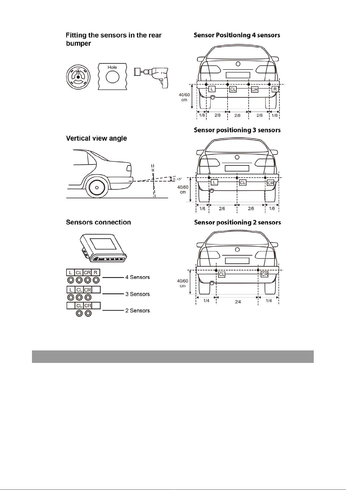
STEP 1 – FITTING THE SENSORS
1. Measure the width of the vehicle and divide by 8.
2. Measure 1/8th from each side and mark location using a marker.
3. Measure from both marks in 2/8th and mark. You now have four marks.
4. Use included hole saw to drill holes at each mark.
5. Fit the sensors (note the orientation on the back of the sensor U!P) and run the sensor cables to the control
module.
See the next page for diagrams.
STEP 2 – POSITION THE CONTROL MODULE AND THE BUZZER/DISPLAY
1. Position the control module in a location where it will be protected from damage, water and dust. Usually the
control unit is mounted behind a panel in the boot close to the rear lights.
2. Position the buzzer/display (model dependent) in a location where it can be easily heard/seen from the driver’s
seat.
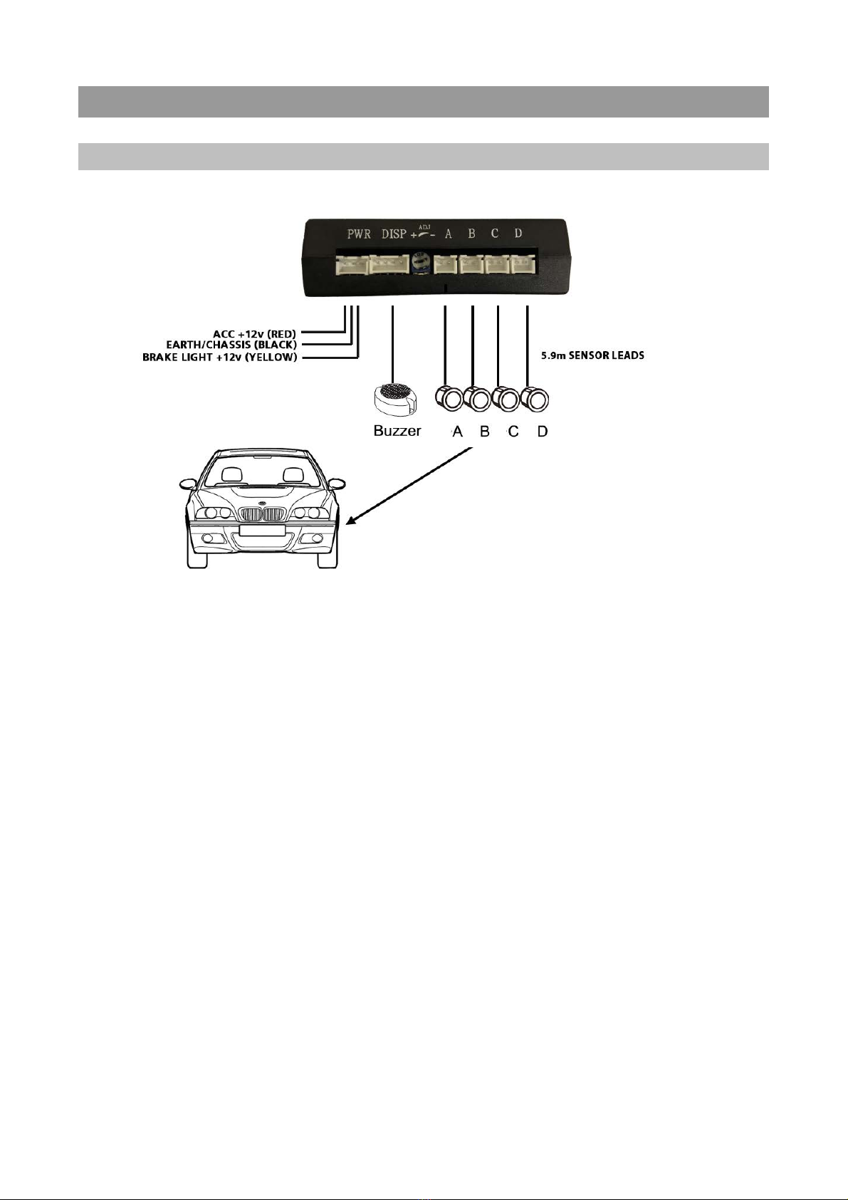
STEP 3 – CONNECTING IT ALL TOGETHER
AVS RS4F
Instructions:
1. Connect the RED wire to ACC (+12VDC) – include the optional override switch (AVSSWITCH) if using.
2. Connect the YELLOW wire to the foot brake light switch (+12VDC when the brake is applied).
3. Connect the BLACK wire to the vehicle’s ground/chassis.
4. Solder and tape all connections.
5. Ensure all sensor plugs and cables are connected correctly and the connectors are locked tight.

AVS RS4R
Instructions:
1. Connect the RED wire to the reverse lights (+12VDC)
2. Connect the BLACK wire to the vehicle’s ground/chassis.
3. Solder and tape all connections.
4. Ensure all sensor plugs and cables are connected correctly and the connectors are locked tight.
5. Connect the buzzer (or optional display if using).

AVS RS8B / RS8D
Instructions:
1. Connect the RED wire to ACC (+12VDC) – include the optional override switch (AVSSWITCH) if using.
2. Connect the BLACK/WHITE wire to the reverse lights (+12VDC).
3. Connect the BLACK wire to the vehicle’s ground/chassis.
4. Connect the BLACK/WHITE wire to the foot brake light switch (+12VDC when the brake is applied).
5. Solder and tape all connections.
6. Ensure all sensor plugs and cables are connected correctly and the connectors are locked tight.
7. Connect buzzer/display.

STEP 4 – OPERATION / TESTING THE REAR SENSORS
When the vehicle is in reverse gear (reverse light on) objects in range of the sensors will be indicated by the
buzzer/display. See the table below:

COMPLEX SITUATIONS
There are some situations where the system will have difficulty detecting obstacles or may give inaccurate
indications.

STEP 4 – OPERATION / TESTING THE FRONT SENSORS
When the brake pedal is pressed the front sensors remain active for 12 secs or 20 seconds depending on the model
(AVS RS8B / AVS RS8D = 12 secs, AVS RS4F = 20 secs). Objects in range of the sensors will be indicated by the
buzzer/display. See the table below:
IMPORTANT NOTES
Ø Parking sensors are an aid to vehicle reversing and parking however they are not a replacement for rear vision
mirrors. Always use the vehicle’s mirror and visually check for obstacles before moving the vehicle.
Ø Reversing speed must never exceed 6km/h.
Ø Immediately stop the vehicle when the buzzer sounds continuously as this indicates an obstacle is within 40cm
of the vehicle.
Ø Disconnect the vehicle battery before making any electrical connections to the vehicle.
Ø The system must only be installed by a professional installer with suitable qualifications, experience and tools.
Ø Clean sensors regularly as dust or snow can reduce accuracy.
Ø If the vehicle is washed with high pressure water jets the sensors can temporarily lose sensitivity. This will return
to normal once the water has completely evaporated.
Ø Do not position the control unit, sensors or cables near heat sources such as the engine or exhaust.
Ø Disconnect power before disconnecting sensors. The system must be restarted after any sensor has been
disconnected/connected. Cycle power before re-testing.

TROUBLE SHOOTING
PROBLEM
CAUSE
SOLUTION
The system fails to start when
vehicle is in reverse gear
Incorrect connection of power
source
Check power lead connections and
control module connector (if
applicable)
The system always detects the
same distance
Sensor is likely detecting the ground
Check and adjust the vertical angle
of the sensor
The system fails to detect obstacles
Sensors are connected incorrectly
Check and reset system e.g. cycle
power
False alarm
Sensor is likely detecting the ground
Check and adjust the vertical angle
of the sensor
TECHNICAL SPECIFICATIONS
Voltage 9.6-15VDC Current 150mA
Operating temperature -20° to 80°C Operating frequency 39.3-40.7KHz
Horizontal detection angle 120° Vertical detection angle 60°
Detection accuracy 1cm Max detection range RS4F 1m
RS4R/RS8B/RS8D 2.5m
Questo manuale è adatto per i seguenti modelli
3
Indice
Altri manuali AVS Elettronica per automobili


