Bahco TA10-D327 Manuale utente

INSTRUCTION MANUAL
BAND CUTTER
TA10-D327
Documentation commissioner:
Andreas Bos
Edition: 02-2017

INSTRUCTION MANUAL
2
TOOL SPECIFICATIONS
Cutting force 10 kN(6 bar / 90 Psi)
Stroke maximum 6,5 mm / 0,26 in
Required free air 1,6 l / Zyklus
Weight 1,3 kgs
Working pressure 5-7 bar
Cuttin gtime < 1 s
Noise level < 75 dB (A)
Vibration < 2,5 m/s²
SAFETY RULES
1. Do not use the tool outside the design intent.
2. Always disconnect the airline from the tool inlet before any service or adjustments.
3. Keep ngers and hands away from the working area when operating the tool.
4. The operating air pressure may not exceed 7 bar / 100 Psi.
5. When using the tool, the wearing of safety glasses is required both by the operator
and others nearby the tool. We recommend the operator to wear gloves.
6. Always adopt a rm footing before operating the tool.
7. The precautions to be observed when using this tool shall be explained by the
customer to all operators.
8. The tool shall be maintained in a safe working condition and examined regularly
by trained and competent personnel.
9. Use only parts with this tool, which are recommended an supplied by BAHCO.
10. Any modi cation undertaken by the customer to the tool, shall be the customers
entire resonsibility.
INTENTION OF USE
This tool is designed to cut sheet metal / steel band, with a maximum dimensions of
2.5 x 33 mm.
INSTRUCTION MANUAL
3
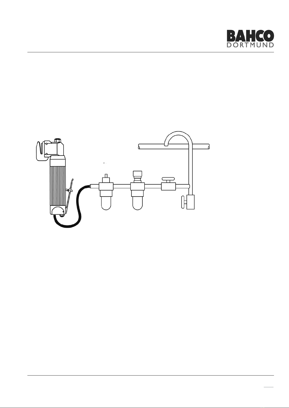
CONNECTION TO THE AIR SUPPLY
We recommend the use of pressure regulators and oiling/ lter systems on the main
air supply (see diagram below). All air hoses must have a minimum inner diameter of
6 mm or 1/4 inch. The tool is operated at an optimum pressure of 6 bar or 90 Psi.
TECHNICAL DESCRIPTION
TA10 is a hydro-pneumatic tool. Its consist of a power unit and a tool head. The
hydropnumatic power unit has an air cylinder connected to a hydraulic cylinder. This
gives a booster eect.
An input of 6 bar/90 Psi air pressure, gives a oil pressure of 177 bar/2655 Psi. The oil
pressure gives the Hydraulic Piston a force of 10 kN and in this tool a stroke
of 6.5 mm/ 0.26 inch. It is a one-way Air Piston with spring return.
The tool is supplied with a Safety Lever (15), which makes it impossible to accidentally
active the tool.
By unscrewing the screws (33), the handle can be adjusted to the most comfortable
working position.
TA10D-327
Lubrication
Pressure gulator
and lter

INSTRUCTION MANUAL
4
MAINTENANCE
PRIMING.
Priming is always necessary after the tool has been dismantled and prior to operating. It
may also be necessary to restore the full stroke after considerable use.
The priming procedure should be carried out in a clean area with clean hands. Ensure
that the oil is perfectly clean and free from air bubbles. Before starting, make shore that
the tool is disconnected from the air supply.
It is important to keep the tool horizontal during the whole procedure.
• Unsrew Oil screws (32).
• Use AWS 32 Hydraulic oil or similar.
• Fill oil into the lowest positioned hole until it comes air free oil from the other hole.
• Replace and tighten the Oil screws (32).
SHARPENING OF THE CUTTING BLADE 3405D.
The Cutting Blade can be used on both sides. Here is how to change side.
• Remove the Pins (36).
• Remove the Cutting Blade (39).
• Move the support bar (41) to the opposite side.
• Turn the piston (37) 180 degree.
• Assembly the Cutting blade (39).
• Assembly the pins (36).
• Priming
• Test

INSTRUCTION MANUAL
5
REPLACING CUTTING BLADE AND CUTTING EDGE.
Dismantling
• Remove the Pins (36)
• Remove the Cutting blade (39)
Assembly
• Assembly in reverse order of dismantling.
• Priming, see above.
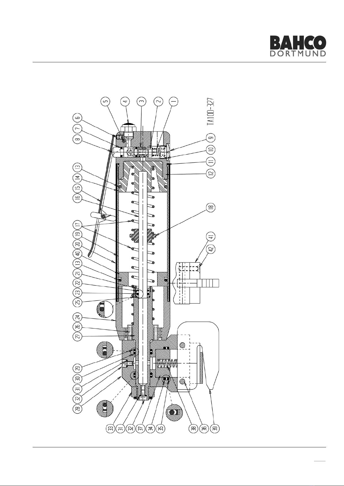
Dismantling Power Unit
• Loosen nut (33)
• Remove cross head (28) from hydraulic piston (27).
Take care of the hydraulic oil.
• Push out pins (36) and remove Cutting blade (39).
• Take away hydraulic piston (37).
• Remove seals (29), (30), (34) and (35). Be careful with seal surfaces!
• Remove hydraulic cylinder (24) together with hydraulic piston (27).
• Unscrew guide (21) and remove seals (22), (23) and (25).
• Remove spring (17), Spring guide (18) pull out air piston (14) together with high
pressure piston (16) and take out O-Ring (13).
• Press out pin (6) and remove lever (15), Valve rod (8), Spring (3) and O-Ring (7).
• Loosen plug (9) and take away spring (1), valve (2) and O-Ring (10).
Assembly
Assembly in reverse order of dismantling.
Priming, see above.

INSTRUCTION MANUAL
6
TROUBLE SHOUTING
SYMPTOM POSSIBLECAUSE REMEDY PAGE
Does not cut Low air pressure Adjust to 5-7 bar / 75-100 Psi 2
Low oil level Prime tool 4
Cutting edges unsharp Sharpening 4
Damaged cutting edges Replace cutting blade and edges 4
Leaks oil Worn or defected seals Replace seals and prime tool 5
POSITION ART. NO. DESCRIPTION QTY
* P-TA10-327 Seal kit 1
17 5830 Spring 2
37 3897 Piston 1
38 5835 Spring 1
39 3405D Cutting blade 1
RECOMMENDED SPARE PARTS
INSTRUCTION MANUAL
7

INSTRUCTION MANUAL
8
NO.QTY DESCRIPTION ART. NO.
1 1 Spring 1336
2 1 Valve 1337
3 1 Spring 1339
4 1 Silencer 1565
5 1 Pin 5448
6 1 Screw 5023
7 2 O - Ring *) 6320
8 1 Valve rod 1553
9 1 Plug 1334
10 1 O - Ring *) 6315
11 1 O - Ring *) 6303
12 1 Valve housing 2087
13 1 O - Ring *) 6353
14 1 Air piston 2086
15 1 Safety lever 3236
16 1 Piston stem 5466
17 2 Spring 5830
18 1 Guide 2198
19 1 Air piston 2194
20 1 Plastic cover 2441
21 1 Guide 2734-2-8
22 1 Bearing *) 6360
23 1 O - Ring *) 6322
24 1 Hydraulic-cylinder 3402-2
25 1 O - Ring *) 6317
NO.QTY DESCRIPTION ART. NO.
26 2 Pin 5406
27 1 Hydraulic-piston 3402-1
28 1 Cross bar 3403
29 2 Bearing *) 6363
30 2 O - Ring *) 6328
31 2 Seal *) 6514
32 2 Oil screw 5047
33 1 Nut 5204
34 1 O - Ring *) 6355
35 1 Bearing *) 6364
36 2 Locking pin 5505
37 1 Hydraulic-piston 3897
38 1 Spring 5835
39 1 Cutting blade 3405D
40 1 Distance sleeve 4588-13
41 1 Support bar 3842-10
42 2 Screw 5088
*) Part of Seal kit REF P-TA10-327
SPARE PART LIST - TA10D-327

BAHCO GmbH & Co.KG
Martener Hellweg 60
DE- 44379 Dortmund
Phone
+49 231 / 91 72 11-0
Fax
+49 231 / 91 72 11-22
www.bahco.de
Indice
Altri manuali Bahco Taglierina


