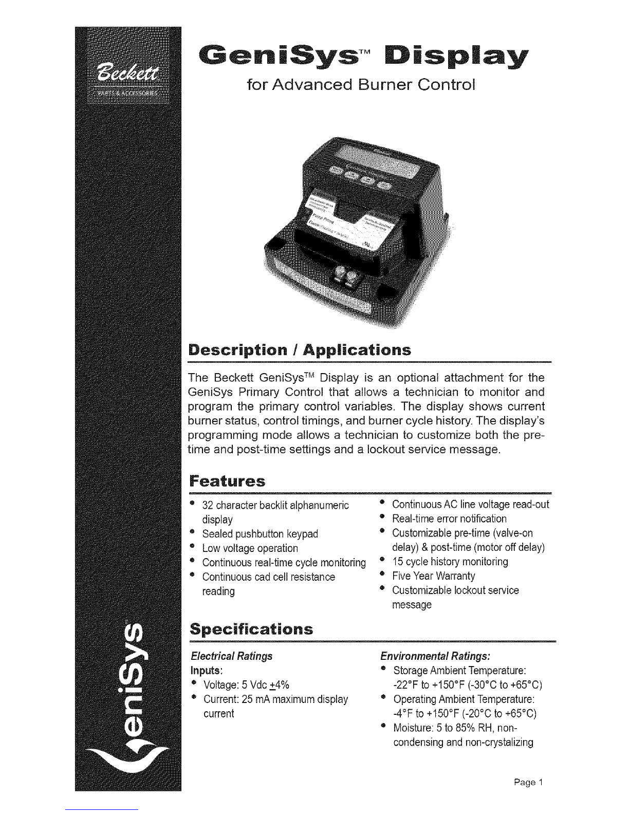
Instailatio.
After removing the protective terminal cover on the
right side of the control, the module is installed across
the top and snapped into place. The module uses two
lines of 16 alphanumeric characters each, to display
the control variables.
tipping the display towards the rear to engage the
rear mounting fingers, then carefully aligning the
display receptacle with the four COM2 pins on the
control, and pressing inplace. No additional fastening
or wiring is required.
With a slotted screwdriver, carefully remove the When the display module is installed on the control,
COM2 port cover on the right side of the GeniSys the readings for the most recent 15 burner cycles can
control. Slide the display down into place by slightly be displayed. Refer to Paragraph B.
Operation
The display was designed to function as both a
monitor and a programmer. The display consists of
two rows of 16alphanumeric characters. Below the
display are 4 keys:
The Back key is used to step back
through the display screens or to reply 'no' to a
question.
The Select key is used to advance
through the display screens or to respond yes to a
question.
Use this key to scroll back to the
previous screen, to decrease pre-time and post-time
timing, and scroll through the character sets when
customizing the Service Message screen.
@Use this key to scroll forward to the next
display screen, to increase pre-time and post-time
timings and to scroll through the character sets when
customizing the Service Message screen.
There are five main functional display groupings within
the module; Burner Status (Paragraph A), Burner
History (Paragraph B), Pre-time Change (Paragraph
C), Post-time Change (Paragraph D) and the Service
Message Program (Paragraph E).
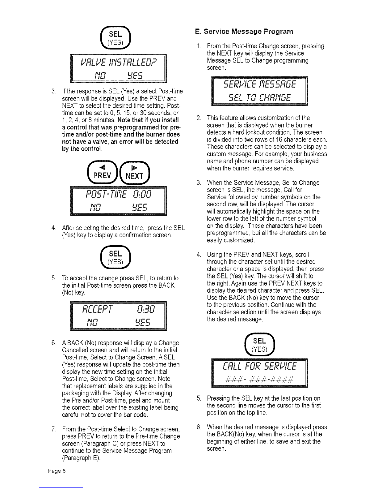
A. Burner Status Mode
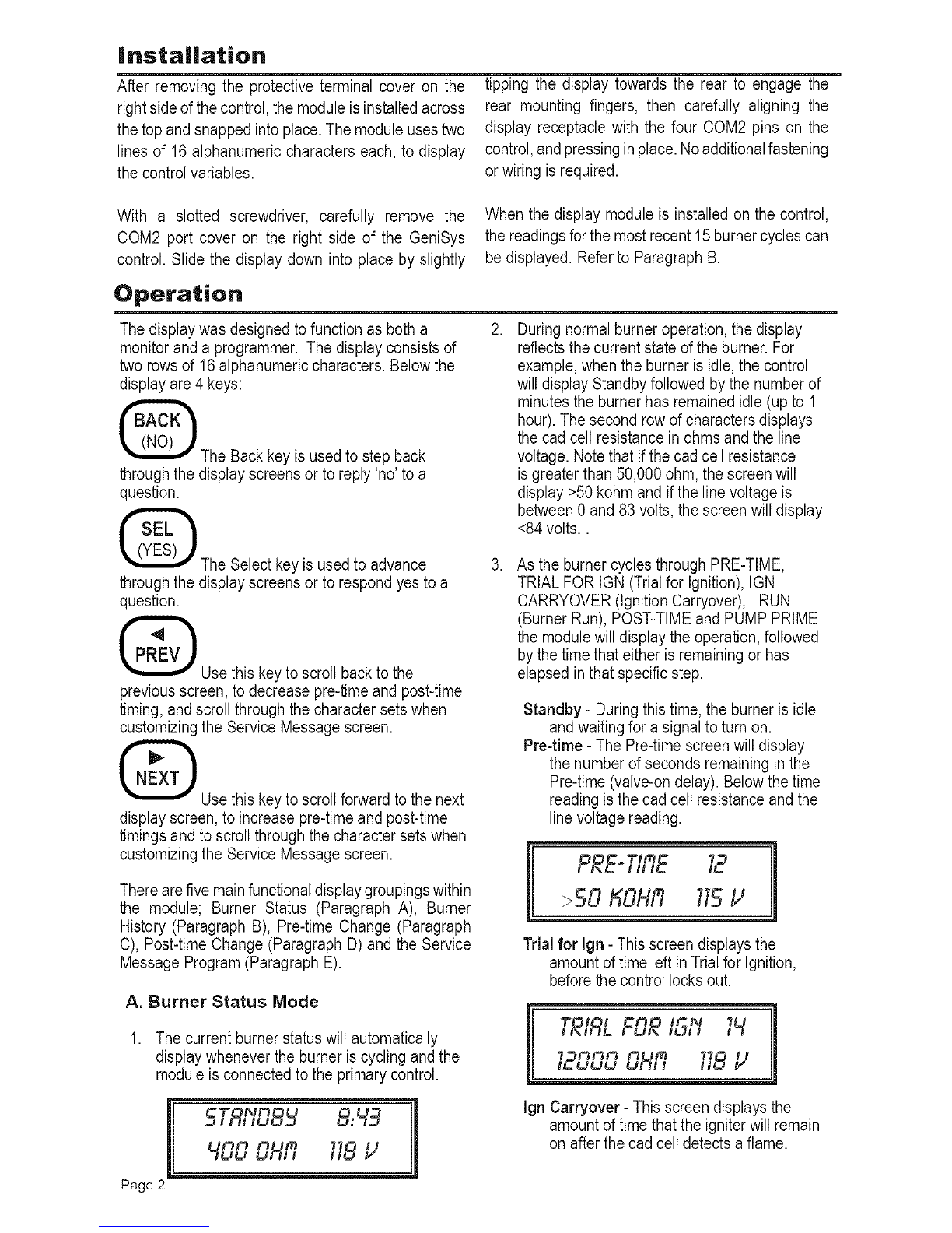
1. The current burner status will automatically
display whenever the burner is cycling and the
module is connected to the primary control.
[ 5TRI'ID8 8:49
400 OHR 718l,;
Page 2 11
2,
3,
During normal burner operation, the display
reflects the current state of the burner. For
example, when the burner is idle, the control
will display Standby followed by the number of
minutes the burner has remained idle (up to 1
hour). The second row of characters displays
the cad cell resistance in ohms and the line
voltage. Note that if the cad cell resistance
is greater than 50,000 ohm, the screen will
display >50 kohm and if the line voltage is
between 0 and 83 volts, the screen will display
<84 volts..
As the burner cycles through PRE-TIME,
TRIAL FOR IGN (Trial for Ignition), IGN
CARRYOVER (Ignition Carryover), RUN
(Burner Run), POST-TIME and PUMP PRIME
the module will display the operation, followed
by the time that either is remaining or has
elapsed in that specific step.
Standby -During this time, the burner is idle
and waiting for a signal to turn on.
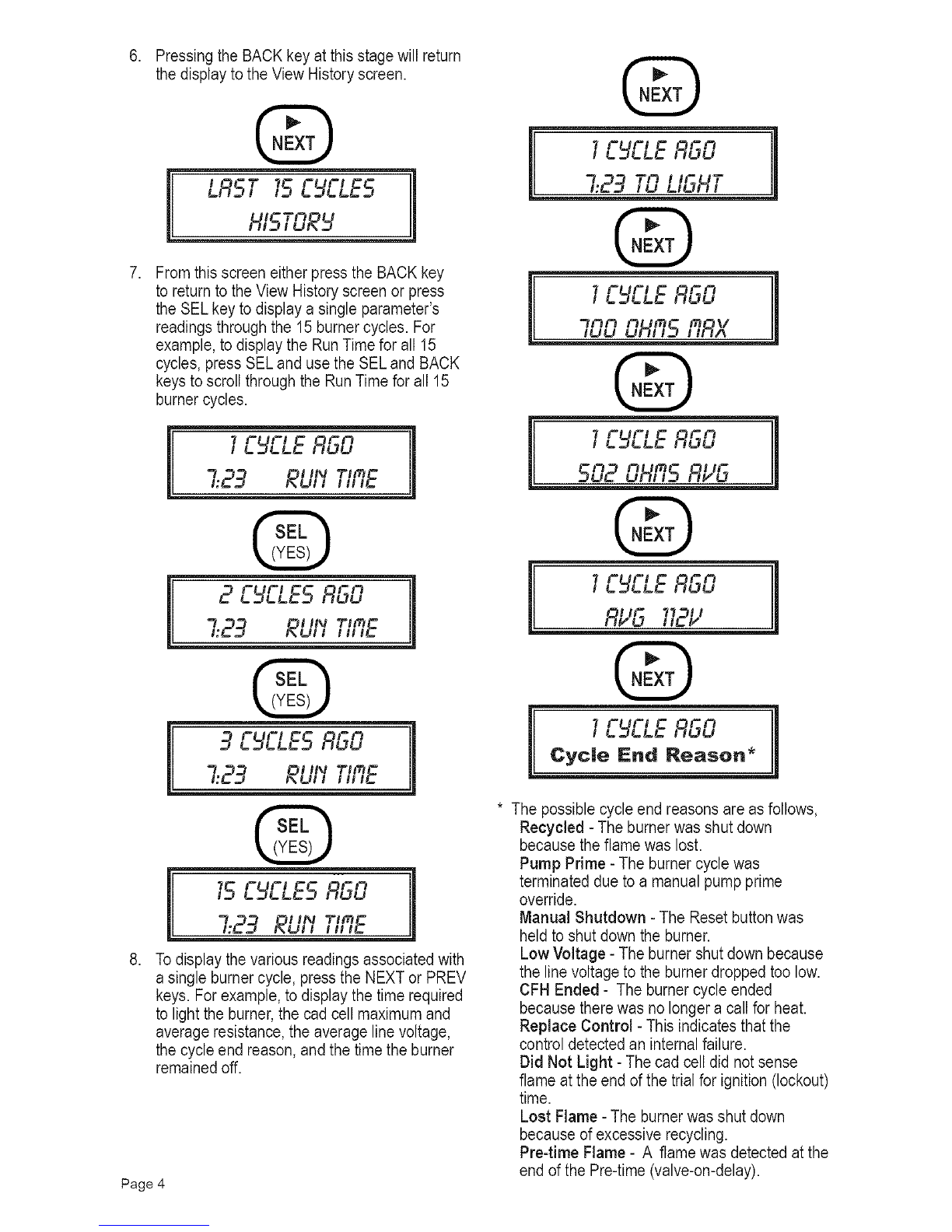
Pre-time -The Pre-time screen will display
the number of seconds remaining in the
Pre-time (valve-on delay). Below the time
reading is the cad cell resistance and the
line voltage reading.
PRE-TIRE 12
>50 KOHfi 11512
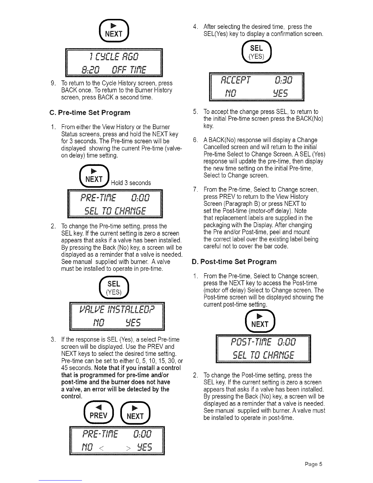
Trial for Ign - This screen displays the
amount of time left in Trial for Ignition,
before the control locks out.
•T_l i
I,,IRL FOR /Sf'I 1_
12000 OHR 118l,"
Ign Carryover -This screen displays the
amount of time that the igniter will remain
on after the cad cell detects a flame.