
BEIFANG VALVE ACTUATOR 920 Series Manuale utente
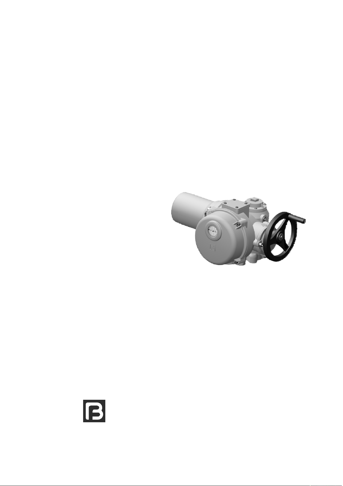
920 SERIES ELECTRIC ACTUATORS
FOR MULTI-TURN APPLICATION
INSTRUCTION MANUAL
TIANJIN BEIFANG VALVE ACTUATOR CO.,LTD
BF/TM-920.03-E2016A
Issue 201603

Tianjin Beifang Valve Actuator Co.,Ltd. 920 series Instruction Manual
1
Thank you for purchasing
and using our products. This
manual is valid for 920 series
electric multi-turn actuators.
Please before you operate
your product, be sure to read this
booklet carefully. These operation
instructions are only valid for
“clockwise closing”, i.e. driven
shaft turns clockwise to close the
valve
Address: Yi Xing Fu Science & Technology
Area Beichen District, Tianjin 300410, China
Tel: 86(022)26308907 26309159
Fax: (022)26300975
http://www.tj-beifang.com
e-mail: bf@tj-beifang.com
Please tell us some information about your
product when contact us:
Model, Factory number, Manufacturing date
WHERE TO FIND INFORMATION
1. Summarize
1.1 Brief
1.2 Range of application
1.3 Warnings and notes
2. Performance parameters
3. Identifiers
4. Structure
4.1 Size 9201
4.2 Sizes 9202~9205
5. Transport and storage
5.1 Transport
5.2 Storage
6. Lubrication
7. Installation
7.1 Installing handwheel
7.2 Installation to valves or gearboxes
7.2.1 Plug sleeve connection
7.2.2 Stem nut connection
8. Electrical connection
8.1 Before wiring
8.2 Wiring
9. Manual operation
10.Setting the torque switch
11.Setting the limit control mechanism
11.1 Setting the limit switch
11.2 Setting the counter
12.Setting the position indicator
13.Installing the cover
页码
2
2
2
2
3
5
6
6
7
8
8
8
8
9
9
9
9
10
11
11
11
12
13
13
13
14
15
16

Tianjin Beifang Valve Actuator Co.,Ltd. 920 series Instruction Manual
2
920 series electric multi-turn actuators provide a reliable position control of
gate, stop valve, as well as similar ones, and they can be combined with
gearbox. About other applications, please contact us.
For any damage caused by improper use, the manufacture is not
responsible for warranty. Such risk shall be borne by user alone. Strictly
complying with the instruction manual is part of the operational requirements.
1. Summarize
1.1 Brief
1.2 Range of application
• 920 series electric multi-turn actuators powered by electric have limit and
torque switch in both end position. In addition they can output torque or
thrust.
• According to customer’s requirements, 920 series electric actuators can be
made the standard type, integral control with open/close, integral control
with regulator module.
1.3 Warnings and notes
Non-observance of the warnings and notes may lead to serious injuries or
damages. Qualified personnel must be thoroughly familiar with all warnings
and notes in these operation instructions.
This sign means:Hint!
Explain the topic in detail.
This sign means :Note!
Non-observance of these notes may lead to the blight to products or
the failure of operation.
This sign means :Warning!
If not carried out the “warnings” correctly can affect the safety of
persons or material.
Tianjin Beifang Valve Actuator Co.,Ltd. 920 series Instruction Manual
3
Standard: 2-G3/4”
Options: 2-NPT1”
2-M33×2
Or according to user need.
Conduit entries
Automatic reset structure for motor mode first. Whenever the motor is
energized, the clutch automatically revert to motor mode in order to ensure
safe operation
The electric actuator can be locked by additional lock.
Hand /auto switch
Continuous display of adjustable dial with “Open” and “Close” mark.position indicator
Torque switches are provided for “Open” and “Close” separately
Standard:1NC and 1NO.
Options:Add up to two torque switches (On and off can be specified by the
user).
Torque control
Limit range of counter from ”Open” to “Close”.
Standard: 1~50 turns.
Options:1~490 turns
Travel switches are provided for “Open” and “Close” separately.
Standard: 1NC and 1NO ( Switches on and off can be changed on the
worksite ).
Options: 1NC and 2NO( Switches on and off can be changed on the
worksite ).
1NC and 3NO ( Switches on and off can be changed on the
worksite ).
Add up to four the middle position switches.
Limit control
Have. The actuator is not self-locking when the output speed is more than
48r/min.
Self-locking
Standard: F, heat resistance.
Options: H, heat resistance.
Insulation grade
A temperature protection switch embedded in the windings of the motor will
trip the actuator control circuit if the motor winding overheat.
Protection
Standard: 380V/50Hz/3ph AC, voltage vibration range:±10%, frequency
vibration range:±5%.
Options: 220V/50H/1ph AC (Apply to 9201 and 9202).
Power
Standard: S2-15 minutes short time work type. No more than 15 minutes
cyclic running time, the startup interval is 2~3 times running time.
60 starts/hour for application, do not exceed 600 starts/hour
when adjusting.
Options: S4-25% intermittent work type. Used for precise adjusting, do not
exceed 1200 starts/hour.
Work type
2. Performance parameters
Tianjin Beifang Valve Actuator Co.,Ltd. 920 series Instruction Manual
4
Options: Flashing switch for runningRunning indicator
Standard: IP65 (GB4208-2008)
Options: IP67 (GB4208-2008)
IP68 (Protection from dust and operating 10 times when
submersing in water to a depth of 3m for 48 hours.)
Ex-proof type: ExdⅡCT4 Gb(GB3836.1-2010、3836.2-2010)
Protection provided by
enclosure
Standard: Epoxy and acrylic acid coating.
Options:Other coating required by customer。
Coating
Standard: Gray (RAL7030)
Option: Other color required by customer.
Coating color
Ambient humidity below 90% (25℃).Humidity
At least 8000 times.(Cycle of operation: Open—Close—open, each cycle is
20 turns).
Lifetime
Standard: Installing the actuator below 2000 meters above seal level.
Options: When installing the actuator above 2000 meters above seal level,
please contact us.
Installation height
Standard: -25℃~ +70℃。
Low temperature type: -40℃~ +70℃。
Ultralow temperature type: -60℃~ +50℃。
Ex-proof: -20℃~ +40℃。
Temperature
Standard: Self-adjusting potentiometer.
Option: Feedback 4~20mA analog position indication signal.
Feedback signal
It is natural that the temperature of the motor surface reach
or exceed 80℃when working, do not touch the motor for
fear scald.

Tianjin Beifang Valve Actuator Co.,Ltd. 920 series Instruction Manual
5
• “BF” logo is cast in the apparent position of each electric actuator.
• Each electric actuator has a nameplate printed with company name, ”BF”
logo, “CE” mark and so on. Content of nameplate includes:
•Type code
•Main code
•Wiring diagram No.
•Maximum torque
•Output speed
•Allowable thrust: Used for stem nut connection
•Supply voltage
•Rate power of motor
•Rate current of motor
•Degree of protection provided by enclosure
•Manufacturing No.
•Manufacturing date
•Address
Content nameplate of ex-proof product also includes:
•Ex-proof degree of protection provide by enclosure
•Certification No.
Only manufacturing No. in each product is a basis of accurately tracing
product. Please keep it well.
3. Identifiers
Tianjin Beifang Valve Actuator Co.,Ltd. 920 series Instruction Manual
6
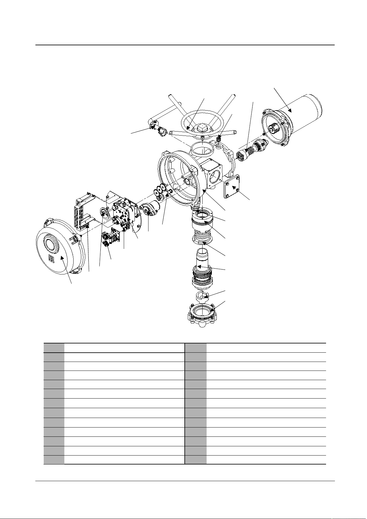
4.Structure
21
20
19
18
17
16
15
14
13
No.
Wiring-box cover
Main house
Conduit entries
Body of handwheel
Clutch
Driven shaft component
Driven sleeve
Output flange
Cover
Name
Terminal strips
Position indicator
Torque switch
Limit switch
counter
Torque transmission component
Limit transmission component
Hand /auto lever component
Handwheel component
Screwed plug for injection grease hole
Worm shaft component
Motor
Name
11
7
5
6
12
10
9
8
4
3
2
1
No.
4.1 Size 9201 1
2
3
4
5
6
7
8
9
10
11
13
14
15
17
16
18
19
20
21
12
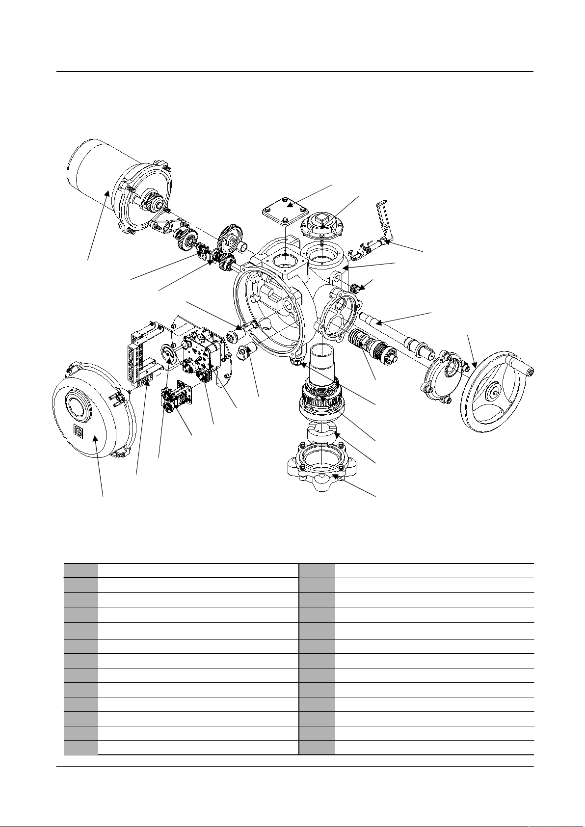
Tianjin Beifang Valve Actuator Co.,Ltd. 920 series Instruction Manual
7
1
4.2 Sizes 9202 ~9205
23
4
5
9
10
6
14
13
12
16
17
18
20
21
19
22
23
7
8
23
22
21
20
19
18
17
16
15
14
13
No.
Wiring-box cover
Housing cover component
Hand /auto lever component
Main house
Screwed plug for injection grease hole
Handwheel shaft
Handwheel component
Worm shaft component
Conduit entries
Driven shaft component
Driven sleeve
Name
Output flange
Cover
Terminal strips
Position indicator
Torque switch
Limit switch
counter
Torque transmission component
Limit transmission component
Clutch
Hand /auto component
Motor
Name
11
7
5
6
12
10
9
8
4
3
2
1
No.
11
15

Tianjin Beifang Valve Actuator Co.,Ltd. 920 series Instruction Manual
8
5. Transport and storage
5.1 Transport •It is necessary to use solid package during transportation.
•When lifting the electric actuator by hoist, please attach ropes or hook
to enclosure. Do not attach ropes or hooks to handwheel, hand/auto
lever or wiring-box.
•If the electric actuator has been mounted to the gearbox, please
attach ropes or hooks to the gearbox rather than to the electric
actuator for the purpose of lifting by hoist.
•If the electric actuator has been mounted to the valve, please attach
ropes or hooks to the valve rather than to the electric actuator for the
purpose of lifting by hoist.
•Do not stand under the dangling electric actuator.
5.2 storage • Units should be stored in the well ventilated, dry, non-corrosive room.
• Units should be placed on bracket or the dry wooden flooring.
• If necessary, units are covered with dust guard.
• Long-term storage (more than 6 months).
• To avoid corrosion, wipe handwheel shaft, driven shaft, driven sleeve and
mounting surface with anti-rust oil.
• Check the units for rust every 6 months. If there is any rust, please treat
again for rust prevention.
6. Lubrication
-25 ~ +120℃Temperature range
Lithium soap thickened mineral oilPrincipal component
• There are O-rings or lip seal between the main house and its contacting
portion. The main house is fully filled with 00# lithium grease to lubricate the
worm shaft, worm gear, gears, bearings and so on.
• No seal can remain absolutely tight at all time, therefore, it is not unusual to
find a very small amount of weeping around shaft sealing-especially during
long periods of idleness such as long-term storage. Once the equipment
has begun operating, this phenomenon will automatically disappear.
• It is not need to refresh the lubricating grease periodically. If the lubricant is
deficient in quantity or its quality has changed, please infuse the lubricating
grease with the same trademark or the same performance from the
injecting grease hole.
00# gear lubricating grease used by the standard units
Tianjin Beifang Valve Actuator Co.,Ltd. 920 series Instruction Manual
9
7. Installation
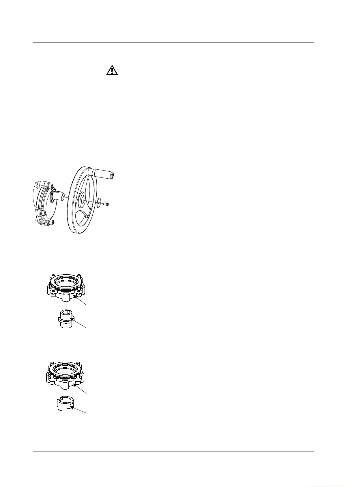
7.1 Installing handwheel For easier transport, the handwheels of sizes 9202~9205 are placed
separately, so please mount the handwheel on the manual shaft, before
doing manual operation.
• Handwheel of size 9201 is directly mounted on the product.
• Design of 920 series ensure man power can drive manual operation, no
need to use the force rod.
7.2 Installation to valves or gearboxes
• Apply for the valve stems which can rotate and not lift: Driven sleeve has
two types of structure-one with hole and keyway and one with jaw.
1.Check whether each mating surface of joint flange fits the valve’s.
2.Check whether dimensions of input shaft and key or jaw in the valve or
gearbox fit the electric actuator’s.
3.Clean up grease on the mating surface of joint flange.
4.When connecting with shaft and key, a little of greases is smeared on the
shaft
5.When installing the electric actuator, tighten the screws after ensuring
mating of the joint flange and shaft or jaw is good.
• Without removing joint flange #1, drive sleeve #2 can be directly removed.
Therefore install the drive sleeve to the shaft or jaw of the valve ,and then
connect the electric actuator with the flange of the valve.
• When the valve stem is shaft with key, the valve stem must have a step for
prevent drive sleeve from moving.
• After installation is complete, check and repair the damage coating .
Material performance level of the parts which connect the electric actuator
with the valve or gear is 8.8 class. Yield strength is 628N/mm² .
7.2.1 Plug sleeve connection
•Warning: If electric actuators are installed in the hazardous gas area,
must check whether the ex-proof degree on the nameplate is
appropriate.
• In the hazardous area, it is prohibited that conductive body and thermal
conductor contact with the electric actuator. Except special allowable work,
the units must be cut off power, remove from the hazardous area for repair
or maintenance.
Driven sleeve with
hole and keyway
Driven sleeve with
jaw
1
2
1
2
Indice
Altri manuali BEIFANG VALVE ACTUATOR Controllori


