Beltrame S2007 Manuale utente


MANUALE S2007 PRELIMINARE.DOC
PAG.2/21
Contents
Contents ..................................................................................................... 2
Important Notice ........................................................................................ 3
1. SAFETY INSTRUCTIONS ...................................................................... 4
1.1 General .................................................................................................... 4
1.2 Safety Instructions..................................................................................... 5
2. DEVICE DESCRIPTION ........................................................................ 6
2.1 Introduction .............................................................................................. 6
2.2 Hardware.................................................................................................. 6
2.2.1 Control elements and interfaces .......................................................... 7
2.2.2 Device connections CN3 ..................................................................... 9
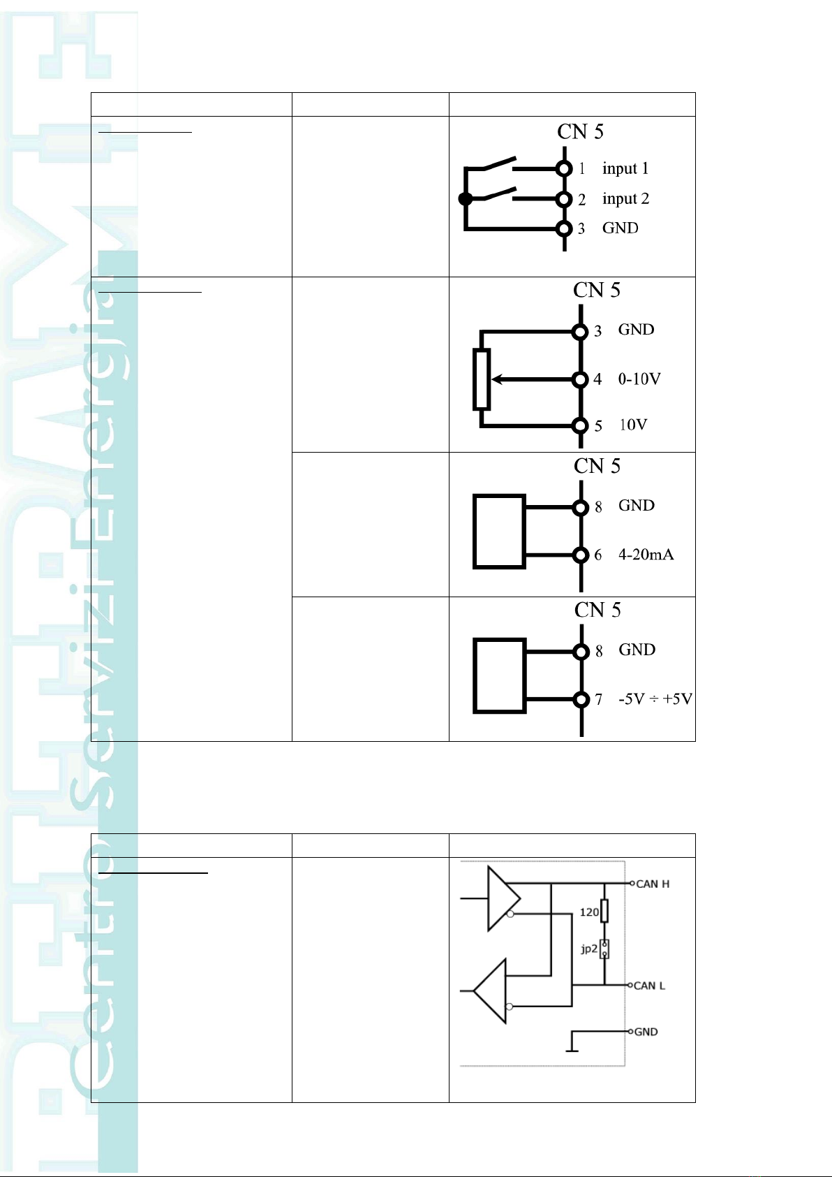
2.2.3 Device connections CN5 ................................................................... 10
2.2.4 Device connections CN2 ................................................................... 10
2.2.5 Device connections CN4 ................................................................... 11
3. OPERATOR INTERFACE ..................................................................... 12
3.1 Set or change parameters......................................................................... 12
3.2 Navigating the menus .............................................................................. 13
3.3 Menu...................................................................................................... 14
3.3.1 Menu d - Display ............................................................................. 14
3.3.2 Menu P - Parameters........................................................................ 14
4. Running the engine........................................................................... 16
4.1 Running the engine .................................................................................. 16
4.1.1 Starting the engine .......................................................................... 16
4.1.2 Governor Performance ..................................................................... 16
4.2 Additional features................................................................................... 17
4.2.1 Real-Time Display............................................................................ 17
4.2.2 Idle Speed ...................................................................................... 17
4.2.3 Speed Droop Operation .................................................................... 17
4.2.4 Overspeed ...................................................................................... 17
4.2.5 Loss of Magnetic Pickup Sensing........................................................ 18
4.2.6 Variable Speed Inputs ...................................................................... 18
5. System troubleshooting .................................................................... 19
5.1 System inoperative .................................................................................. 19
5.2 Insufficient Magnetic Speed Signal ............................................................. 19
5.3 Electromagnetic Compatibility (EMC)................................................................ 19
5.4 Instability ................................................................................................. 20
6. Specifications ................................................................................... 21
6.1 Performance............................................................................................ 21
6.2 Enviromental........................................................................................... 21
6.3 Compliance/ standards ............................................................................. 21
6.4 Input/output ........................................................................................... 21
6.5 Reliability ............................................................................................... 21
6.6 Physical .................................................................................................. 21

MANUALE S2007 PRELIMINARE.DOC
PAG.3/21
Important Notice
Our experience has shown that, if the information and recommendations contained
in this Operating Instructions are observed, the best possible reliability of our
products is assured.
The data contained herein purports solely to describe the product and is not a
warranty of performance or characteristics. It is with the best interests of our
customers in mind that we constantly strive to improve our products and keep them
abreast of advances in technology. This may, however, lead to discrepancies
between a product and its "Technical Description" or " Operating Instructions".
This document has been carefully prepared and reviewed, however should in spite of
this the reader find an error, he is requested to inform us at his earliest convenience.
It is scarcely possible for the operating instructions for technical equipment to cover
every eventuality, which can occur in practice. We would therefore request you to
notify us or our agent in the case of all unusual behaviour that does not appear to be
covered by these operating instructions.
It is pointed out that all local regulations must be observed when connecting and
commissioning this equipment in addition to these operating instructions.
We cannot accept any responsibility for damage incurred as a result of mishandling
the equipment regardless of whether particular reference is made in these operating
instructions or not.
We lay particular stress on the fact that only genuine spare parts should be used for
replacements.
All rights with respect to this document, including applications for patent and
registration of other industrial property rights, are reserved. Unauthorized use, in
particular reproduction or making available to third parties, is prohibited.
Manufacturer’s address

MANUALE S2007 PRELIMINARE.DOC
PAG.4/21
1. SAFETY INSTRUCTIONS
1.1 General
The safety instructions shall be followed during installation, commissioning, operation and
maintenance. Read all instructions carefully before operating the device and keep this
manual for future reference.
Required Qualification
Personnel involved in installation work and commissioning of the S2007 must be
familiar, specially instructed and informed about the residual danger areas according
to the regulations currently in force.
Operating personnel is not permitted to work at the control system.
Specially instructed personnel must only carry out maintenance and repair work.
The maintenance personnel must be informed about the emergency shutdown
measures and must be capable of turning off the system in case of emergency.
The maintenance personnel must be familiar with the accident prevention measures
at their workplace and must be instructed in first aid and fire fighting.
It is the owner’s responsibility to ensure that each person involved in the installation
and commissioning of the S2007 has received the appropriate training or instructions
and has thoroughly read and clearly understood the safety instructions in this
chapter.

MANUALE S2007 PRELIMINARE.DOC
PAG.5/21
1.2 Safety Instructions
The safety instructions always appear at the beginning of each chapter and/or
precede any instruction in the context where a potentially dangerous situation may
appear. The safety instructions are divided into five categories and emphasized by
the use of the following layout and safety signs:
DANGER!
This symbol indicates an imminent danger resulting from
mechanical forces or high voltage. A non-observance leads to
life-threatening physical injury or death.
WARNING!
This symbol indicates a dangerous situation. A non-observance
may lead to bad or life-threatening physical injury or death.
CAUTION!
This symbol indicates a dangerous situation. A non-observance
may lead to physical injury or cause damage to the device.
NOTICE!
This symbol emphasizes important information. A non-
observance may cause damage to the device or to objects close
to it.
IMPORTANT!
This symbol indicates useful information. Not to be used to
indicate dangerous situations.

MANUALE S2007 PRELIMINARE.DOC
PAG.6/21
2. DEVICE DESCRIPTION
2.1 Introduction
The S2007 is an electronic device designed to control engine speed with fast and
precise response to transient load changes.
This closed loop control, when connected to a proportional electric actuator and
supplied with a magnetic speed sensor signal, will control a wide variety of engines in
an isochronous or droop mode.
It is designed for high reliability and built ruggedly to withstand the engine
environment.
A practical and simple-to-operate panel on the unit is used for all control operations.
In addition, user-friendly software facilitates commissioning and allows optimization
of operation.
The mechanical construction is compact and robust.
2.2 Hardware
Structure:
The device, placed inside a plastic box, is submerged in resin allowing so the
maximum resistance against engine vibrations and a reliability with time.
Control elements:
A 4 digit 7-segment display is located on it in order to allow an easy visualization of
parameters. The use of push buttons placed at the side and below the display allows
to scroll the menu of all parameters and to set those of interest.
Installation:
Mounting:
The S2007 is designed for wall mounting on a metal panel.
Mounting on a non-dissipative surface such as a plastic panel may lead to device
overheating and is to be avoided.
For optimal cooling is to keep free a minimum distance of 100 mm all around the
unit.
Connection diagram:
Basic electrical connections are illustrated in the figure below.

MANUALE S2007 PRELIMINARE.DOC
PAG.7/21
2.2.1 Control elements and interfaces
Carrying out settings on the unit
The display and the four keys are sufficient to allow complete operation.
All settings can be carried out directly on the unit without additional equipment
Input/Output configuration
Parameter setting
Display of main measures.

MANUALE S2007 PRELIMINARE.DOC
PAG.8/21
Terminal blocks
Overview of full device connections
CN2 –CAN BUS interface
1. CAN H
2. CAN L
3. GND CAN
4. n.c.
5. n.c.
6. n.c.
7. GND CAN
8. n.c.
CN3 –Inputs/Outputs
1. Actuator -
2. Actuator +
3. Battery –(GND/COM)
CN4 –RS232 interface
1. Reserved (do NOT use!)
2. Tx
3. Rx
4. Reserved (do NOT use!)
5. GND
6. Reserved (do NOT use!)
7. Reserved (do NOT use!)
8. Reserved (do NOT use!)
9. Reserved (do NOT use!)
CN5 –Inputs/Outputs
1. Digital input (COM=GND)
2. Digital input (COM=GND)

MANUALE S2007 PRELIMINARE.DOC
PAG.9/21
4. Battery + (12÷24Vdc)
5. Out aux (Solenoid valve)
6. Pickup +
7. Pickup –
8. UP (COM=GND)
9. DOWN (COM=GND)
10. IDLE (COM=GND)
3. GND/COM
4. Analog input 0÷10V
5. Supply output +10V (max 20mA)
6. Analog input 4÷20mA
7. Analog input -5÷5V
8. GND/COM
n.c. = not connected
2.2.2 Device connections CN3
Terminal designation
Signal
Specifications
Actuator
DC output
12÷24Vdc
0÷12 A (15A for 10s)
Solenoid valve
Digital output
12÷24Vdc
2Amax
Pickup
Passive pickup
Active pickup
or
Up
Digital Input
Down
Digital Input
IDLE
Digital Input

MANUALE S2007 PRELIMINARE.DOC
PAG.10/21
2.2.3 Device connections CN5
Terminal designation
Signal
Specifications
Digital inputs
2 digital inputs
programmable function
Analog inputs
analog input
0÷10Vdc
(Potentiometer
=2k÷ 5k
0,25W)
analog input
4÷20mA
analog input
-5V ÷ +5V
2.2.4 Device connections CN2
Terminal designation
Signal
Specifications
Communication
CAN
selectable termination
Altri manuali per S2007
1
Indice
Altri manuali Beltrame Controllori


