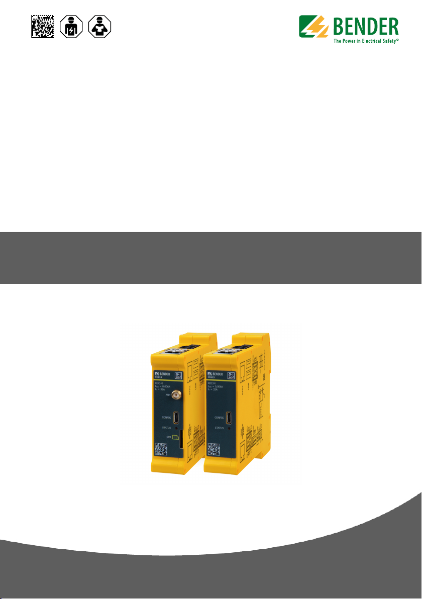
CC613 charge controller
Table of contents
1Gene al inst uctions.........................................................................................5
1.1 How to use the manual..............................................................................................................................5
1.2 Indication of important instructions and information................................................................... 5
1.2.1 Signs and symbols........................................................................................................................................5
1.3 Service and Support.................................................................................................................................... 5
1.4 Training courses and seminars................................................................................................................ 5
1.5 Delivery conditions...................................................................................................................................... 6
1.6 Inspection, transport and storage..........................................................................................................6
1.7 Warranty and liability.................................................................................................................................. 6
1. Disposal of Bender devices.......................................................................................................................6
1.9 Safety................................................................................................................................................................. 7
2Function.............................................................................................................8
2.1 Intended use...................................................................................................................................................
2.2 Device features (depending on the variant)......................................................................................
2.3 Product description..................................................................................................................................... 9
2.4 Functional description................................................................................................................................9
2.5 General functions (depending on the variant)..................................................................................9
2.6 Temperature monitoring - Load current and cooling monitoring...........................................10
2.7 LED indications............................................................................................................................................11
3Dimensions and mounting............................................................................ 12
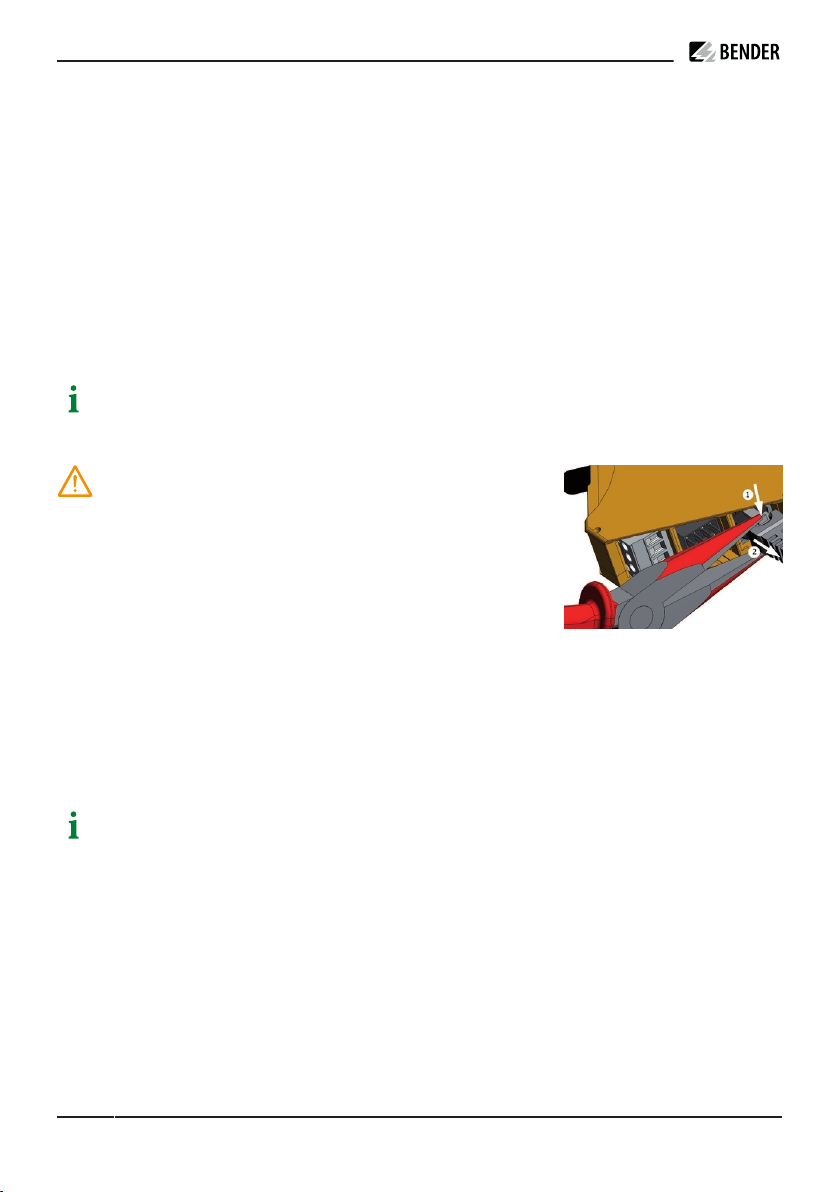
4Connection...................................................................................................... 13
4.1 Connection plug connections...............................................................................................................13
4.2 Wiring diagram............................................................................................................................................14
4.3 Connectivity..................................................................................................................................................17
4.3.1 Master/slave connection ........................................................................................................................ 17
4.3.2 Interfaces....................................................................................................................................................... 17
4.3.3 Power contactor connection..................................................................................................................17
4.3.4 PE monitoring..............................................................................................................................................19
4.3.5 Control Pilot (CP) and Proximity Pilot connections (PP).............................................................. 20
4.3.6 I/O extension (depending on the variant).......................................................................................21
4.3.7 Emergency opener.................................................................................................................................... 21
4.3. Residual direct current monitoring module (RDC-M)...................................................................21
4.3.9 Connectivity with Modbus meters...................................................................................................... 21
CC613_D003 1_07_M_XXEN/02.2023 3