Binks MX1212 Manuale utente

77-2925
page 1 of 16
We reserve the right to change the specifications without prior notice.
© ITW INDUSTRIAL FINISHING 2010
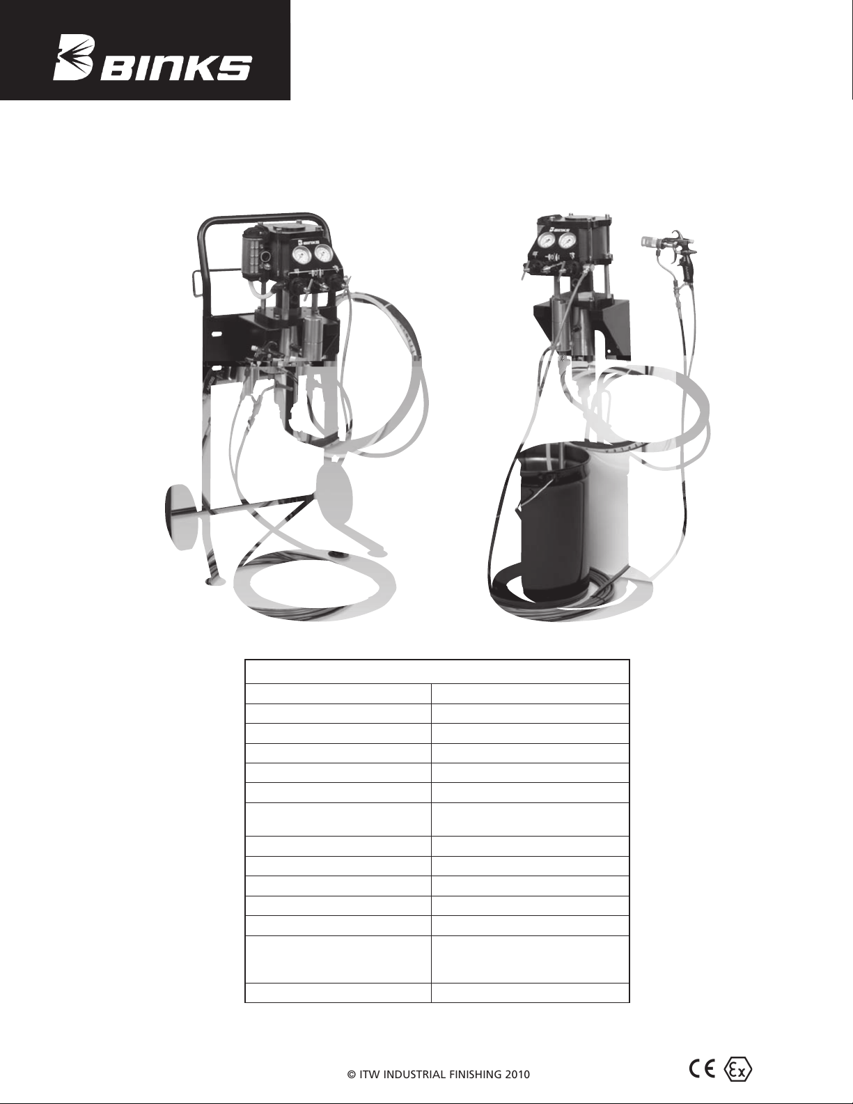
MX1212
12:1 Pump Systems for
Air Assist & Airless Finishing
Patent 7,603,855
SPECIFICATIONS
Ratio: 12:1
Maximum air inlet pressure: 8 bar [116 psi]
Maximum fluid pressure: 96 bar [1390 psi]
Displacement per cycle: 72 cc [2.4 oz]
Output @ 60 cycles/min: 4.3 L /m [1.2 gal/m]
Air consumption @ 20 cycles/min: 147 L PM [5.2 SCFM]
Maximimum recommended
continuous cycle rate: 20 cycles/min
Air inlet connection: 3/8" BSP(f) and 1/4" NPS(m)
Air piston diameter: 85 mm [3.3 in]
Stroke length: 75 mm [3.0 in]
Fluid inlet connection: 3/4" NPS(m)
Fluid outlet connection: 3/8" BSP(m) / 3/8" NPS(m)
Wetted parts materials of
construction:
Stainless Steel, Tungsten Carbide,
Hard Chrome, PTFE, Polyethylene,
Leather
Sound level: 96.2 dB

77-2925
page 2 of 16
In this part sheet, the words WARNING, CAUTION and NOTE are used to emphasize important safety information as follows:
Read the following warnings before using this equipment.
FOR FURTHER SAFETY INFORMATION REGARDING BINKS AND DEVILBISS EQUIPMENT,
SEE THE GENERAL EQUIPMENT SAFETY BOOKLET (77-5300).
READ THE MANUAL
Before operating finishing equipment, read and
understand all safety, operation and maintenance
information provided in the operation manual.
AUTOMATIC EQUIPMENT
Automatic equipment may start suddenly without
warning.
INSPECT THE EQUIPMENT DAILY
Inspect the equipment for worn or broken parts
on a daily basis. Do not operate the equipment
if you are uncertain about its condition.
NEVER MODIFY THE EQUIPMENT
Do not modify the equipment unless the
manufacturer provides written approval.
KNOW WHERE AND HOW TO SHUT OFF THE
EQUIPMENT IN CASE OF AN EMERGENCY
PRESSURE RELIEF PROCEDURE
Always follow the pressure relief procedure in the
equipment instruction manual.
NOISE LEVELS
The A-Weighted sound level of pumping
equipment and spray guns may exceed 85 dB (A)
depending on the set-up being used. Details of
actual noise levels are available on request. It is
recommended that ear protection is worn at all
times when spraying while pump is operating.
HIGH PRESSURE CONSIDERATION
High pressure can cause serious injury. Relieve all
pressure before servicing. Spray from the spray
gun, hose leaks, or ruptured components can
inject fluid into your body and cause extremely
serious injury.
WEAR SAFETY GLASSES
Failure to wear safety glasses with side shields
could result in serious eye injury or blindness.
DE-ENERGIZE, DEPRESSURIZE, DISCONNECT
AND LOCK OUT ALL POWER SOURCES DURING
MAINTENANCE
Failure to De-energize, disconnect and lock out
all power supplies before performing equipment
maintenance could cause serious injury or death.
OPERATOR TRAINING
All personnel must be trained before operating
finishing equipment.
EQUIPMENT MISUSE HAZARD
Equipment misuse can cause the equip ment to
rupture, malfunction, or start unexpectedly and
result in serious injury.
KEEP EQUIPMENT GUARDS IN PLACE
Do not operate the equipment if the safety
devices have been removed.
PROJECTILE HAZARD
You may be injured by venting liquids or gases
that are released under pressure, or flying debris.
PINCH POINT HAZARD
Moving parts can crush and cut. Pinch points are
basically any areas where there are moving parts.
STATIC CHARGE
Fluid may develop a static charge that must be
dissipated through proper grounding of the
equipment, objects to be sprayed and all other
electrically conductive objects in the dispensing
area. Improper grounding or sparks can cause a
hazardous condition and result in fire, explosion
or electric shock and other serious injury.
NOTE
Important installation, operation or
maintenance information.
CAUTION
Hazards or unsafe practices which could
result in minor personal injury, product
or property damage.
!
WARNING
Hazards or unsafe practices which could
result in severe personal injury, death or
substantial property damage.
!
Warning
!
IT IS THE RESPONSIBILITY OF THE EMPLOYER TO PROVIDE THIS INFORMATION
TO THE OPERATOR OF THE EQUIPMENT.
PACEMAKER WARNING
You are in the presence of magnetic fields which
may interfere with the operation of certain
pacemakers.

77-2925
page 3 of 16
Warning
HIGH PRESSURE CAN CAUSE SERIOUS INJURY IF EQUIPMENT IS INSTALLED OR USED INCORRECTLY—
READ, UNDERSTAND, AND OBSERVE ALL WARNINGS AND INSTRUCTIONS IN THIS MANUAL.
INSTALL, OPERATE OR SERVICE THIS EQUIPMENT ONLY AFTER
ALL INSTRUCTIONS ARE CLEARLY UNDERSTOOD.
It is the responsibility of the employer to place this information into the hands of the operator.
!
CAUTION
Hazards or unsafe practices which could
result in minor personal injury, product
or property damage.
!
WARNING
Hazards or unsafe practices which could
result in severe personal injury, death or
substantial property damage.
!
NOTE
Important installation, operation or
maintenance information.
AVOID STATIC SPARKING
1. Use Binks NO-WIRE conductive hose
in all airless spraying operations. Be
sure the gun and hose have continuity.
2. Make sure the pump is grounded.
NEVER operate the unit when it is on
a non-grounded platform.
3. When flushing or cleaning with a
combustible solvent, always use an
open metallic container for receiving
the waste solvent. Ground the solvent
receptacle.
4. ALWAYS remove spray tip when
flushing the system. Operate the pump
at the lowest possible pressure.
Bonding Wire,
Gun To Solvent Container
Conductive Hose
To Airless Pump
Open
Metallic
Waste Solvent
Container,
Grounded
GENERAL WARNINGS
1. NEVER leave a pressurized sprayer
unattended.
2. Periodically inspect all hoses for leaks
and/or abrasions and tighten all
connections before use. DO NOT
ATTEMPT TO REPAIR a defective
hose. REPLACE it with another
conductive hose.
3. ALWAYS relieve pressure in the
system by turning bypass valve to
BYPASS or triggering spray gun
before disassembly of any component
parts.
CAUTION
Never store de-ionized, distilled, reverse
osmosis or any pure grade of water in the
pump. These fluids may cause corrosion.
NOTE
BINKS is not responsible for misapplica-
tion of pumps. Consult your BINKS repre-
sentative for application assistance.
REPLACEMENT PARTS
The pump is designed to use authorized
parts only. When using this pump with
parts that do not comply with the
minimum specifications and safety
devices of Binks, the user assumes all
risks and liabilities.
WARNING
EXCESSIVE AIR PRESSURE
Can cause personal injury, pump dam-
age or property damage. Do not exceed
maximum inlet air pressure as stated on
motor model plate.
!
NOTE
Be sure that all fluids, solvents and
fillers to be used are chemically and
physically compatible with wetted
parts in the pump. Consult your BINKS
representative for pump materials of
constructions and compatibility infor-
mation. Consult the fluid manufacture
for information regarding the fluids to
be used.

77-2925
page 4 of 16
HAZARD CAUSE SAFEGUARDS
EXPLOSION STATIC ELECTRICITY
Use of this equipment in
a potentially explosive
atmosphere.
Vapors from flammable
liquids can catch fire
or explode from static
electricity discharges.
1. If installing this equipment in a potentially explosive
atmosphere, check the ATEX equipment category and
temperature ratings meet the requirements for the
zoned area.
2. Check electrical continuity of the air supply to earth —
should be no greater than 106 .
3. Electrically bond all metallic equipment to earth.
Should be no greater than 1 .
SPECIAL
CONDITIONS
FOR SAFE USE
REQUIRED
BY ATEX
CERTIFICATION
Over pressurization of
equipment can cause
equipment failure or injury.
Use lubricating medium
resistant to carburisation.
Improper operation or
maintenance may create a
hazard.
1. Do not exceed the stated maximum working pressures
and motor speed as specified in this manual.
2. Only a suitably approved static dissipating or
conductive air supply hoses shall be attached to the
equipment and terminated to the air supply.
3. Air supplies (compressors, etc.) shall be sited in a non-
hazardous area with a filter on the air intake system to
prevent the ingress of dust or similar foreign material
into the parts where compression takes place.
4. Use lubricating medium resistant to carburisation and
has an auto ignition temperature of more than 185ºC
for T4 equipment.
5. User shall ensure all metallic parts of the equipment
are suitably bonded to earth. Should be no greater
than 1 .
EC Declaration of Conformity
We:
As the manufacturer of the items listed below:
Piston Pumps MX412 MX432 MX1212 MX1231
Declare, under our sole responsibility, that, the equipment to which this document relates is in conformity with the fol-
lowing standards or other normative documents:
EN 13463-1:2009, EN 13463-5:2005, EN 982:1996 + A1:2008, EN 983:1996 + A1:2008 and EN 12621:2006
And thereby conform to the protection requirements of Council Directive 98/37/EC relating to Machinery Safety Directive and
council Directive 94/9/EC relating to Equipment and Protective Systems intended for use in Potentially Explosive
Atmospheres;
CE Ex 2 II Gc T4
Issued on: 1st July 2009
Authorized by:
General Manager
Technical file lodged with;
TRL Compliance Ltd (Notified Body 0891)
Moss View
Nipe Lane
Up Holland
WN8 9PY, UK
Binks, Ringwood Road, Bournemouth, BH11 9LH, UK

77-2925
page 5 of 16
STARTUP AND OPERATION
(Part numbers referenced are contained
in the MX1212 bare pump assemblies
part sheet: 77-2926.)
GROUNDING THE BINKS PUMP
WARNING
To prevent static charging igniting the
flammable spray material, the BINKS
pump must be grounded before it is
started up. A grounding cable is
included with the pump.
!
1. Clamp the grounding cable to the
terminal on the high pressure filter or
the air motor.
2. Connect the other end of the grounding
cable to a suitable grounding device
(e.g. grounding bar).
PREPARING TO START UP THE
BINKS PUMP
Proceed as follows:
1. Check that the solvent cup
is full to the level shown.
If necessary, add material
to the solvent cup. (Order
part no. 0114-009433 for solvent
based paint, and part no. 0114-014871
for waterborne paint.)
2. Select a suitable filter element using
the table in this manual (page 9) and
insert it into to the high pressure filter
(0115-010326).
3. Attach a suitable fluid hose to the
outlet fitting (0114-016059) on the
high pressure filter (0110-009130).
WARNING
The fluid hose supplied by BINKS is
identified with the maximum
permitted working pressure and the
bursting pressure. The lesser value —
the maximum permitted working
pressure—must be greater than the
maximum permitted working pressure
of the pump.
!
4. Connect the gun—designed at least
for the maximum permitted working
pressure of the pump—to the fluid hose.
5. Make sure that the ball valve on the air
control assembly is closed.
6. Connect the compressed air supply to
the air inlet connection.
7. The pump is equipped with an air
pressure regulator (0115-010183).
Before putting the pressure line
into operation, relieve the pressure
regulator by fully unscrewing the
regulating screw. Thereafter rotate
the regulating screw clockwise until
the pressure gauge (0115-010192) on
the regulator indicates the required
pressure.
NOTE
The pump is equipped with an air
pressure safety valve (0114-014774)
set at 8 bar (116 psi).
RINSING THE BINKS PUMP
WARNING
Wear eye protection.
!
Every BINKS pump is tested with water
during final inspection and thoroughly
rinsed with a non-gumming preservative
oil. With this rinsing process, it is
possible that the residual moisture of
water emulsion will be left in the pump.
Before the unit is started up for the first
time, a suitable solvent must be used to
thoroughly rinse out the remains of the
preservative fluid and the unavoidable
impurities introduced during equipment
assembly.
Proceed as follows:
1. Prepare the BINKS pump for start-up
as shown above.
2. Close the high pressure ball valve
(0114-019091) on the fluid filter.
3. Immerse the suction system in the tank
of solvent.
4. Insert the return flow hose (0114-
009103) into the tank of solvent.
Open the high pressure ball valve
(0114-019091) on the fluid filter.
5. Open the ball valve and set the
air regulator (0115-010183) to
approximately 1 bar (14.5 psi). The
suction system now draws in the
solvent. The solvent runs back to the
solvent tank through the high pressure
filter (0110-009130), the high pressure
ball valve (0114-019091) and the
return flow hose (0110-009103).
6. Remove the spray tip from the gun and
point the gun into the tank. Unlock
the safety lever on the gun, operate
the gun and close the high pressure
ball valve. The solvent will now flow
through the high pressure filter, the
fluid hose and the gun, back into the
tank. The time of rinsing depends on
the length of the material lines and
the solubility of the spray material.
We recommend a short reflush with
"fresh" solvent.
7. Release the gun trigger.
8. Slowly increase the pressure at the
regulator to maximum working
pressure while checking and testing
that all lines and screw and plug caps
are tightly sealed. If there are any
leaks in the system, shut down the
BINKS pump immediately. Only re-
start the BINKS pump once you have
repaired the leak.
9. Reduce the air pressure at the air
regulator (0115-010183) again and
close the ball valve.
10. Make sure that the return flow hose
(0110-009103) is still directed into
the solvent tank. Carefully open
the high pressure ball valve (0114-
019091) to reduce the pressure in the
fluid hose and in the high pressure
filter.
11. Point the gun into the tank of solvent
and operate the trigger, to reduce any
pressure which may still exist in the
fluid hose and in the gun.
CAUTION
If working with waterborne material,
the BINKS pump must again be
thoroughly rinsed with water before it
is started up.
!
START-UP
1. Prepare the BINKS pump for start-up
as shown above and if necessary, rinse
pump.
2. Close the high pressure ball valve
(0114-019091) on the fluid filter.
3. Immerse the suction system in the
spray material to be used.
4. Place the return flow hose (0110-
009103) in the tank. Then open the high
pressure ball valve (0114-019091).
5. Open the ball valve for the compressed
air supply and use the pressure
regulator (0115-010183) to set the
compressed air supply to 1 bar (14.5
psi). The pump will now draw in the
spray material. The spray material
flows back into the tank through the
high pressure filter, the high pressure
ball valve and the return pipe.
(continued on next page)

77-2925
page 6 of 16
6. Remove the spray tip from the gun and
point the gun into the tank. Unlock the
safety lever on the gun. Operate the
gun trigger and close the high pressure
ball valve (0114-019091). The spray
material will now flow through the
high pressure filter, the fluid hose and
the gun, back into the tank.
7. Release the gun trigger and set the
working pressure at the regulator.
NOTE
Before carrying out any coating work, we
recommend a test spray (e.g. on to paper
or wood). Only if the test gives you the
desired result should you start to coat the
actual object.
WORK STOPPAGES
CAUTION
If working with 2-K spray material, you
must note the given pot life and follow
it precisely. Within this time, the unit
must be carefully cleaned and rinsed
with the recommended solvent. There
must be no residue left in the pump,
the high pressure filter or the gun.
!
CAUTION
When work is stopped, the safety lever
of the gun must be locked.
!
For work stoppages of between 10 and
30 minutes, please proceed as follows:
WARNING
Wear eye protection.
!
1. Lock the safety lever on the gun.
2. Shut off the compressed air supply by
closing the ball valve.
3. Briefly open the high pressure ball
valve (0114-019091), taking care that
the return flow hose (0110-009103)
is not pointed at other people or
at yourself, until the pressure has
reduced. Then close the high pressure
ball valve again.
4. Clean the outside of the spray nozzle
from spray material residue.
SHUT-DOWN
CAUTION
Once work is completed, the BINKS
pump must be thoroughly cleaned.
Under no circumstances must you
allow paint residue to dry out in the
unit. To clean the pump, use a solvent
appropriate to the spray material.
!
WARNING
Wear eye protection.
!
1. Close the ball valve for the compressed
air supply.
2. Make sure that the flow hose (0110-
009103) is still directed into the spray
material tank. Carefully open the high
pressure ball valve (0114-019091) to
reduce the pressure in the pump and in
the high pressure filter.
3. Remove the spray tip from the gun.
4. Point the gun into the tank of spray
material and operate the trigger to
reduce any pressure which may still
exist in the fluid hose and in the gun.
5. Lock the safety lever on the gun.
6. Remove the suction system from the
spray material.
CLEANING YOUR BINKS PUMP
CAUTION
Do not allow spray material or solvent
to soak into the ground.
!
WARNING
Wear eye protection.
!
1. Clean the pump and the suction system
from the outside. Immerse the suction
system in the tank of solvent.
2. Clean the fluid tip/tip system as
described in the service bulletin of the
spray gun. We recommend to soak the
fluid tip in solvent.
3. Unlock the safety lever of the gun
without fluid tip. Operate the gun.
Close the high pressure ball valve
(0114-01909). Set the air inlet pressure
to 1 bar (14.5 psi) and slowly open
the ball valve. Let the solvent run
through the system so that the spraying
material can rinse out.
4. Let the solvent run through the system
for a couple of minutes until the
solvent runs clear through the gun.
Close the ball valve and lock the safety
lever of the gun
5. Clean the gun from the outside and
check the filter on the handle (if
mounted).
6. Clean the filter element of the high
pressure filter.
7. Clean the filter of the suction system.
8. We recommend keeping the pump
filled with liquid.
NOTE
If the pump is not to be used for longer
periods of time, we recommend flushing
the system with a light, silicone-free oil.
STARTUP AND OPERATION

77-2925
page 7 of 16
SYSTEM COMPONENTS LIST
ITEM
NO.
PART
NUMBER DESCRIPTION
0015-1212F-AC 0015-1212F-AC-P 0015-1212F-AC-PU 0015-1212F-AL 0015-1212F-AL-P 0015-1212F-AL-PU
SERVICE
BULLETIN
1
0115-010186 TROLLEY ASSEMBLY 1 1 1 1 1 1
2
0115-010179 WALL BRACKET 1 1 1 1 1 1
3
0115-010001 SOCKET HEAD CAP SCREW 4 4 4 4 4 4
4
0115-010030 HEX NUT 4 4 4 4 4 4
5
0115-010031 LOCKWASHER 4 4 4 4 4 4
6
0115-010035 PLAIN WASHER 4 4 4 4 4 4
7
MX1212PL MX1212 BARE PUMP ASSEMBLY (PTFE/Leather) 1 0 0 1 0 0 77-2926
MX1212PP MX1212 BARE PUMP ASSEMBLY (PTFE) 0 1 0 0 1 0 77-2926
MX1212PU MX1212 BARE PUMP ASSEMBLY (PTFE/UHMW) 0 0 1 0 0 1 77-2926
8
0115-010180 AIR ASSIST AIR CONTROL 1 1 1 0 0 0
0115-010198 AIRLESS AIR CONTROL 0 0 0 1 1 1
9
0114-009164 ELBOW FITTING 1 1 1 0 0 0
10
0110-009130 HP FILTER ASSEMBLY (100 mesh) 1 1 1 1 1 1
11
0115-010236 SUCTION HOSE ASSEMBLY (20 mesh) 1 1 1 1 1 1
MX1212 CART MOUNTED ASSEMBLIES

77-2925
page 8 of 16
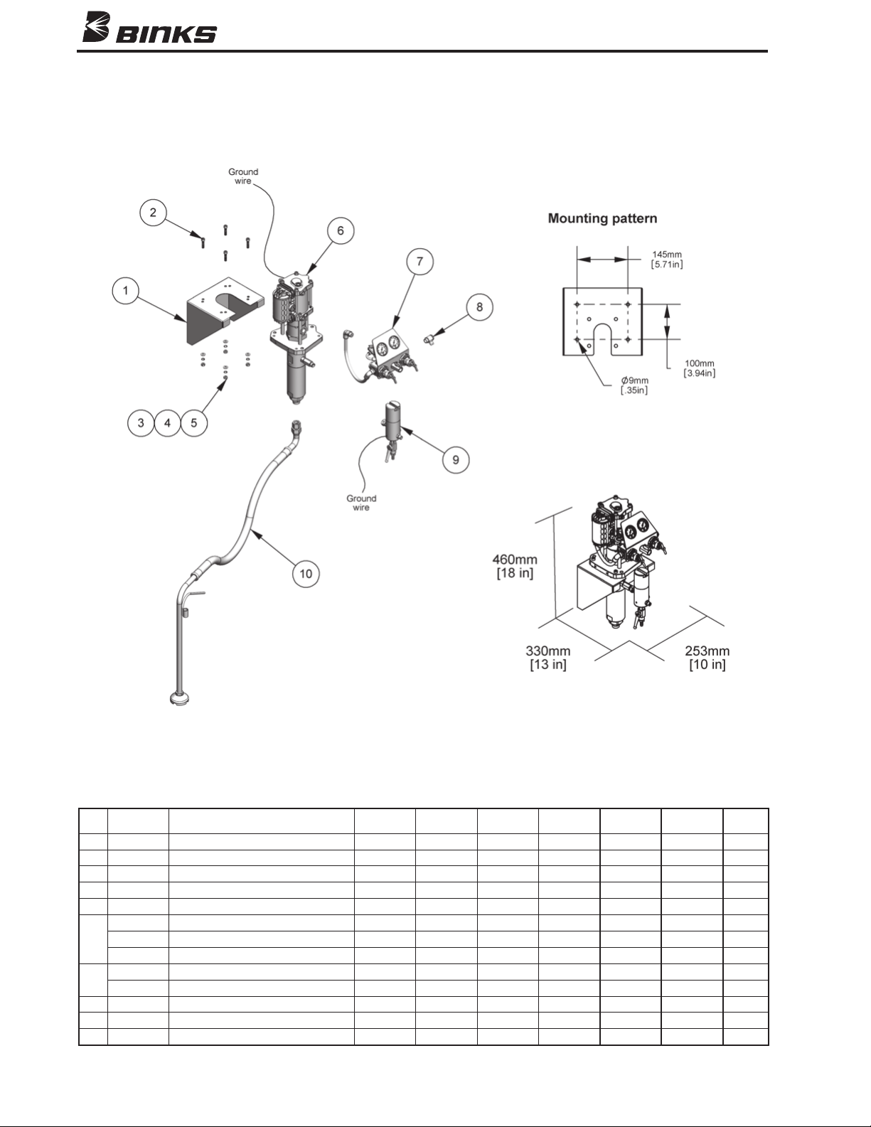
MX1212 WALL MOUNTED ASSEMBLIES
SYSTEM COMPONENTS LIST
ITEM
NO.
PART
NUMBER DESCRIPTION
0015-1212W-AC 0015-1212W-AC-P
0015-1212W-AC-PU
0015-1212W-AL 0015-1212W-AL-P
0015-1212W-AL-PU
SERVICE
BULLETIN
1
0115-010179 WALL BRACKET 1 1 1 1 1 1
2
0115-010001 SOCKET HEAD CAP SCREW 4 4 4 4 4 4
3
0115-010030 HEX NUT 4 4 4 4 4 4
4
0115-010031 LOCKWASHER 4 4 4 4 4 4
5
0115-010035 PLAIN WASHER 4 4 4 4 4 4
6
MX1212PL MX1212 BARE PUMP ASSEMBLY (PTFE/Leather) 1 0 0 1 0 0 77-2926
MX1212PP MX1212 BARE PUMP ASSEMBLY (PTFE) 0 1 0 0 1 0 77-2926
MX1212PU MX1212 BARE PUMP ASSEMBLY (PTFE/UHMW) 0 0 1 0 0 1 77-2926
7
0115-010180 AIR ASSIST AIR CONTROL 1 1 1 0 0 0
0115-010198 AIRLESS AIR CONTROL 0 0 0 1 1 1
8
0114-009164 ELBOW FITTING 1 1 1 0 0 0
9
0110-009130 HP FILTER ASSEMBLY (100 mesh) 1 1 1 1 1 1
10
0115-010236 SUCTION HOSE ASSEMBLY (20 mesh) 1 1 1 1 1 1

77-2925
page 9 of 16
SPECIFICATIONS
Max working pressure: 500 bar [7200 psi]
Fluid inlet connection: 3/8" BSP (f)
Fluid outlet connection: 1/4" NPS (m)
Wetted parts materials of
construction: Stainless Steel, PTFE
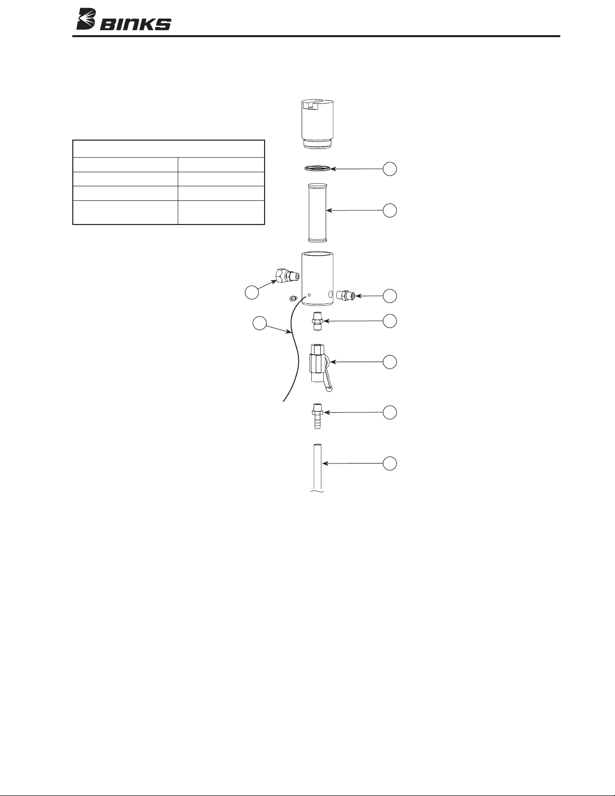
0110-009130 HIGH PRESSURE FILTER ASSEMBLY (100 MESH FILTER ELEMENT)
1 0114-016061 GASKET .......................................................... 1
2 0110-009132 100-MESH FILTER ELEMENT .......................... 1
3 0110-016058 INLET SWIVEL FITTING,
3/8 BSPT(M) x 3/8 BSPP(F)
.. 1
4 0114-016059 OUTLET FITTING, 1/4 NPT(M) x 1/4 NPS(M) ........ 1
5 0114-016243 GROUNDING WIRE KIT ................................. 1
6 0114-019090 OUTFLOW FITTING ........................................ 1
7 0114-019091 HIGH PRESSURE BALL VALVE ....................... 1
8 0114-019092 HOSE NIPPLE .................................................. 1
9 0110-009103 RETURN FLOW HOSE, 3/8 ID x 1/2 OD.............. 1
ITEM PART
NO. NO. DESCRIPTION QTY.
Additional filter mesh sizes (sold separately):
0110-009131 50 mesh
0010-009133 150 mesh
0010-009060 200 mesh
PARTS LIST
When ordering, please specify Part No.
1
2
4
5
3
6
7
8
9

77-2925
page 10 of 16
0115-010180 AIR ASSIST AIR CONTROL ASSEMBLY
ITEM PART
NO. NO. DESCRIPTION QTY.
PARTS LIST
When ordering, please specify Part No.
1 0115-010181 ELBOW FITTING ............................................. 2
2 0115-010185 TUBING .......................................................... 1
3 0115-010183 • AIR REGULATOR 0–160 PSI (0–11 BAR) .............. 1
4 0115-010189 QUIK CLAMP ................................................. 2
5 0115-010188 MANIFOLD BLOCK ........................................ 1
6 0115-010182 • AIR REGULATOR 0–60 PSI (0–4 BAR) ................. 1
7 0115-010194 PANEL MOUNT NUT ...................................... 2
8 0115-010334 MINI BALL VALVE .......................................... 1
9 0115-010333 DM ADAPTER ................................................ 1
10 0115-010193 DUAL REGULATOR PANEL ............................ 1
11 0115-010191 PANEL MOUNT GAUGE 0–60 PSI (0–4 BAR) ...... 1
12 0115-010192 PANEL MOUNT GAUGE 0–160 PSI (0–11 BAR)... 1
13 0115-010195 90º ELBOW SWIVEL TUBE FITTING ............... 2
14 0115-010197 TUBING .......................................................... 2
15 0115-010196 90º ELBOW GAUGE TUBE FITTING ............... 2
16 0115-010324 SWIVEL FITTING, 3/8 BSPT (M) X 3/8 BSP( F) ...... 1
17 0115-010157 AIR CONTROL MOUNTING STUD ................. 1
• Regulator Repair Kit
(sold separately):
0115-010228
Indice
Altri manuali Binks Spruzzatore di vernice

Binks
Binks EMG Series Manuale utente

Binks
Binks HAP 50 Series Manuale utente

Binks
Binks SV100 Manuale utente

Binks
Binks MAG AA Manuale utente

Binks
Binks 2100 SERIES Manuale utente

Binks
Binks 59-10001 A Manuale utente

Binks
Binks TROPHY 2466 SERIES Manuale utente

Binks
Binks 7 Manuale utente

Binks
Binks TROPHY 2465 Series Manuale utente

Binks
Binks 460 Manuale utente

Binks
Binks 95A Manuale utente

Binks
Binks 550 Manuale utente

Binks
Binks Cub SLG Manuale utente

Binks
Binks AA4400M Manuale utente

Binks
Binks AA4400A Manuale utente

Binks
Binks M1-G HVLP Manuale di riferimento

Binks
Binks TROPHY SERIES Manuale utente

Binks
Binks 0811-7500-4 Manuale utente

Binks
Binks Airless 75 Manuale utente

Binks
Binks 7D Manuale utente