BISEN PY-L Guida

PY-L DC Brushless Sliding Gate Opener
INSTALLATION MANUAL & USER GUIDE

WARNING TO THE INSTEALLER AND USER
CAUTION! For personal safety it is important to follow all the instructions
carefully.Incorrect installation or misuse of the product may cause serious harm to
people.
Keep the instructions in a safe place for future reference.
This product was designed and manufactured strictly for the use indicated in this
document. Any other usage not expressly indicated in this Document,may damage
the product and /or be a source of danger.
BS accepts no responsibility due to improper use of the automatic machine (open-
er) or use other than that intended.
Do not install the machine in an area subject to explosion hazard.Inflammable
gasses or fumes are a serious safety hazard.
BS will not accept responsibility if the rules of good workmanship are disregarded
in installig the closing elements to be motorised, if any deformation occurs during
use of the said elements.
Before carrying out any work on the system, turn off the electricity supply.
The safety devices(e.g.photocells,sensitive edges,etc … ) may be used to prevent
any potential risk in dangerous areas where the moving mechanism is located,
such as crushing, dragging, or shearing.
BS accepts no responsibility regarding safety and correct operation of the
machine, should components made by manufacturers other than we be used in
the system.
Do not make any alterations to the components of the automatic machine (opener
and accessory ).
The installer must supply full information regarding operation manual of the
system in the event of any emergency and provide the system user with the
“INSTRUCTION”included with the product.
Do not allow children of other people to stand nera any moving part of the opener
or door construction while in operation.
Keep transmitters away from children to prevent the machine from being activated
accidentally.
The user must refrain from attempting to repair or adjust the system personally
and should only contact professional personnel.
Frequently examine the installation, in particular check cables, springs and
mountings for signs of wear, damage or imbalance, Do not use if repair or
adjustment is needed since a fault in installation or an incorrectly balanced door
may cause injury.
1)
2)
3)
4)
5)
6)
7)
8)
9)
10)
11)
12)
13)
14)
15)
16)
17)
18)
19)
20)
21)
22)
23)
24)
25)
This appliance is not intended for use by persons(including children)with reduced
physical, sensory or mental capabilities, or lack of experience and knowledge,
unless they have been given supervision or instruction concerning use of the ap-
pliance by a person responsible for their safety.
If the supply cord is damaged, it must be replaced by the manufacturer, its service
agent or similarly qualified persons in order to avoid a hazard.
Disconnect the supply when cleaning or other maintenance is being carried out, if
the appliance is automatically controlled.
The temperature range marked on the drive should be suitable for the location.
The electrical cord plug must plug in indoor outlet or waterproof cover outlet.
Ensure that entrapment between the driven part and the surrounding fixed parts
due to the opening movement of the driven part is avoided.
After installation, ensure that the mechanism is properly adjusted and that the pro-
tection system and any manual release function correctly;
Permanently fix the label concerning the manual release adjacent to its actuating
member.
The drive cannot used with a driven part incorporating a wicket door.
Children should be supervised to ensure that they do not play with theappliance
1. Introduction

⑴
⑵
⑶
⑷
⑸
⑹
⑺
⑻
⑼
⑽
⑾
262 mm 165 mm
198 mm
248 mm
58 mm
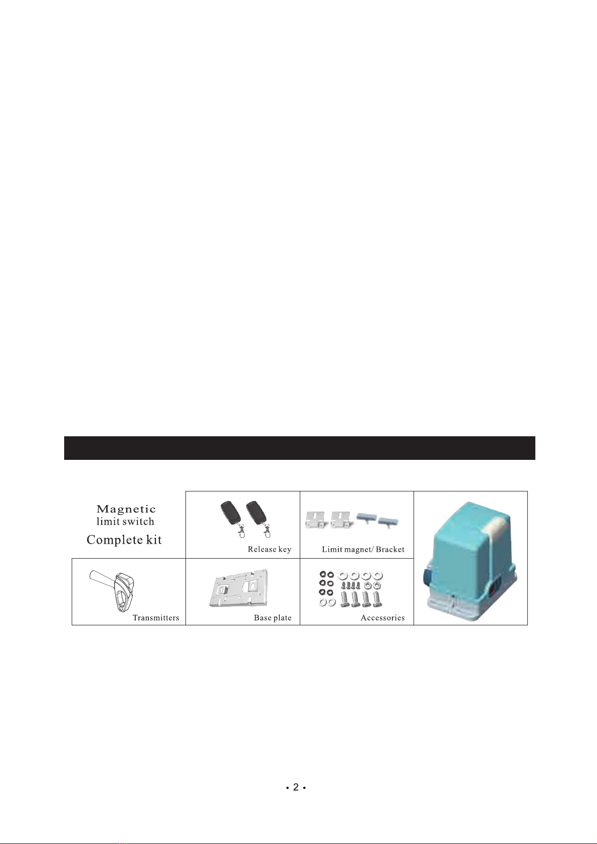
1.1 Main Components
1.2 Dimension
Built-in control board.
Terminals for Push button,Photocell,Alarm lamp.
Auto-closing is available,time delay is adjustable.
(1) Gearbox
(2) Release Clutch
(3) DC Motor
(4) Electromagnetic Brake
(5) Transformer
(6) LED Light
(7) Motor Cover
(8) Gear Reducer
(9) Control Board
(10) Limit Switch
(11) Output Pinion

4
Model
Type
Motor voltage
Motor Power
Output rotational speed
Operate speed
Max weight of gate
Working temperature
Remote range
BS-PY82L-120DC
DC Brushless Motor
24VDC
120W
54r/min
12m/min
<1200Kg
-30℃~+60℃
≥30m
1.4 Feature
1.3 Technical Specifications
1.The eletromagnetic brake could lock the operator when power off.
2.In case of power failure, the gate can be opened and closed manually after
release clutch.
3. Soft start function.
4.Reverse or stop when meet obstacle, the two functions is optional.
5.Soft stop or limit brake function is optional.
6.Auto close delay function.
7.Applicable to access control system.

2.1 Example of a sliding gate operator installation
Before using the machine, check power supply, grounding, voltage, etc.
Check whether it is connected according to the demand of wiring diagram.
The gate should be pulled easily and smoothly manually when the worm gears are
released.
The worm gears will be coupled before power on.
The product must be installed by professional person.
Means for disconnection must be incorporated in the fixed wiring in accordance
with the wiring rules.
The diameter of wire on the wall not less than 1mm²,the diameter of wire that con-
nect to appliance not less than 0.5mm²
The external diameter of power line not more than 14mm, the power line should
have polychloroprene sheathed cable and at least normal polychloroprene
sheathed cable.
2. Installation
BS-PY82L
Alarm Lamp
Gate wheel
Photocell (Optional)
Rack
Transmitter
Photocell (Optional)
1
2
3
4
5
6
7+8
2
3
4
5
6
7
8
1

6
2.2.1 Install baseplate on the ground, then,fasten the sliding motor on the baseplate.
Key: Ensure baseplate on level position.
M8 Bolt
Door opener
Base Plate
2.2 installation and adjustment
~
Bolt
Output pinion of sliding gate opener
Rack
173m
m
300mm
20mm
B
AC
Power
>300mm
Baseplate
Baseplate
Wheel
Slide way
Gate
Rack
Expansion
Bolt
Concrete base

7
AC Fire line
Null line
220V
2.2.2 Before place the limit magnet on the rack, the gear box of the operator
must be released asper Fig7, use the key turn clockwise to release the gear.
release key
unlock
lock
release cover
2.3 Power Connection
Rack
Gate
Output Pinion
Wheel
Slide way
Gasket
Base plate
Fig7
Concrete base

8
DIP1--DIP3 back up
DIP4:
ON: Change running direction of motor, if the motor rotate in opposite direction,
turn this switch.
OFF: Default state display.
Running state display:
1 2 3 4
ON DP
Dip switch
Function
Opening Closing Stop
Reach open limit Reach close limit
Set transmitter
LED Set transmitter
button
DIP Switch
Loop
Close
Stop
Open
Photoccll
Close limit
Open limit
Electromagnetic
Brake
Motor wires
Transformer
24V input
LED
Alarm Lamp
Yellow
Green
Blue
10A Fuse
Airwave
switch
Receiue Trans
mitter
Y G B
3. Control board
Display
9
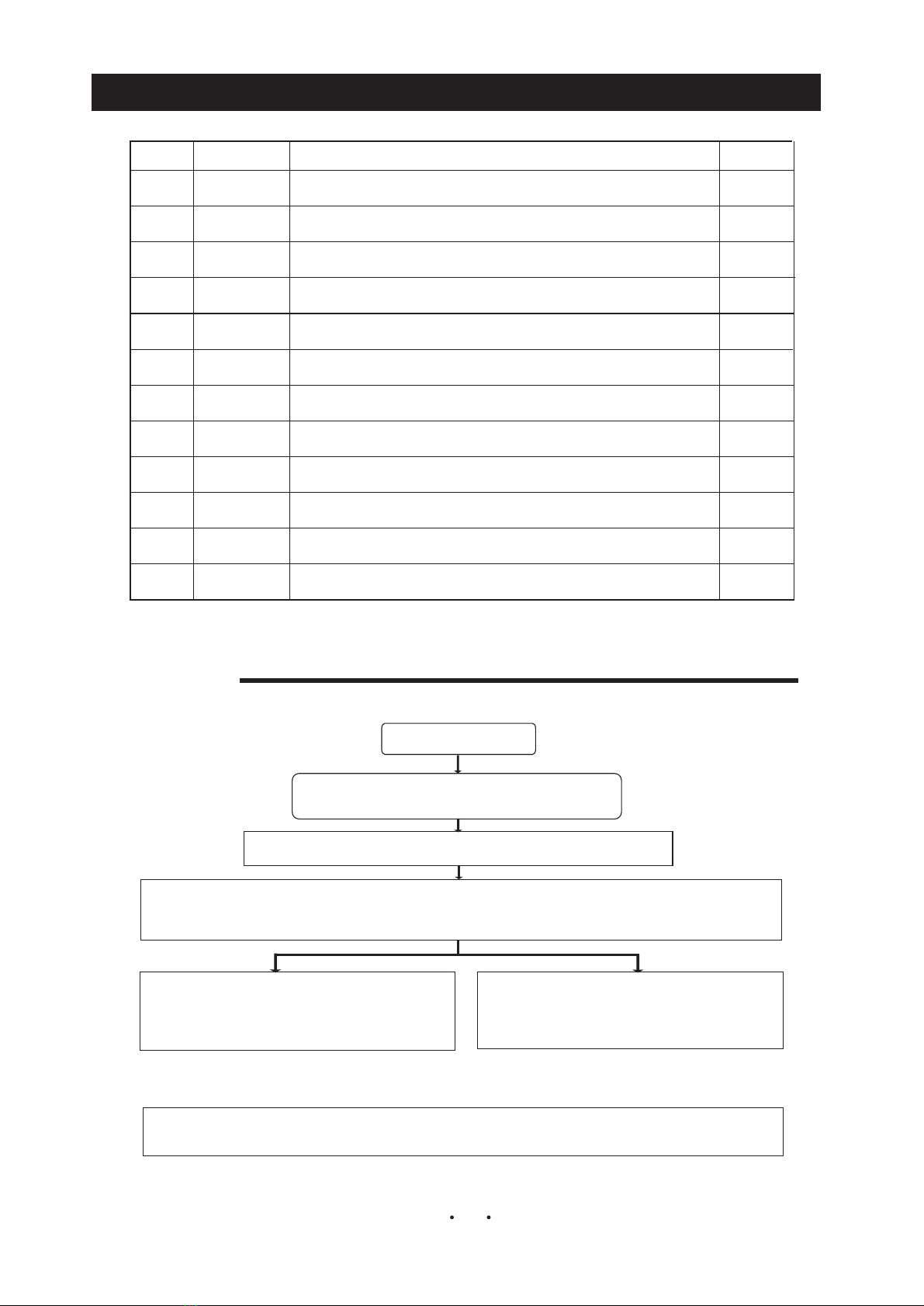
4.1 Setting
Press and hold “SET” for 3 seconds, display “P1”
Power on
Press “OPEN” or “CLOSE” to switch Parameters
Each click “OPEN” increases value by 1; press and hold “OPEN” value increase till reduse the button.
Each click “CLOSE” reduces value by 1; press and hold “CLOSE” value reduced till reduse the button.
Press "SET" ,enter next parameter set interface
(Save parameter only finish setting the final interface).
Mark : 1. In any state from "P1" to "L2", press "STOP " to save parameters.
2. In“L2”state,press "SET" to save parameters.
Press "STOP" save and quit set interface
Px setting ,X=1-9
No Parameter Description
Protect time for motor running,unit:second,motor will stop when over time
Motor speed:Lever 1 to 5 ,Min=1, Max=5
Reduce speed distance : 0-15
Sensitivity of reverse when obstacle 0-50
Limit set : 0=Normal Open, 1=Normal Close
Auto close delay time: 0-99. 0=no Auto close
Sofe stop reduce speed 1-5, 1=Fastest, 5=Slowest
Sofe stop, 0=no Soft stop, 1=valid
Test mode for engineer only default=0
Brake rate for engineer only default=0
Display mode. 0=Running state, for engineer only, default=0
Motor speed when the first time after power on, lever1 to 5 ,Min=1, Max=5
Factory set
1
2
3
4
6
7
5
8
9
10
11
P1
P2
P3
P4
P5
P6
P7
L0
L1
P8
P9
20
1
1
1
0
0
0
80
4
3
6
12
L2
0
4. Parameters setting
Questo manuale è adatto per i seguenti modelli
1
Indice
Altri manuali BISEN Apricancello


