Black & Webster Products Division
545 Hupp Ave. P.O. Box 831, Jackson, MI 49203
Phone: (517- 787-9444 Fax: (517) 787-7585
Email: info@airhydraulics.com
3
Warranty
Air-Hydraulics, Inc. warrants to the original user that all products manufactured will be free from
defects in material and workmanship and will possess the characteristics represented in writing
by us. Claim for breach of the above warranty must be made within a period of one year from
date of delivery to the user. Upon satisfactory proof of claim, we will make any necessary
repairs or corrections, or at our discretion, replace defective parts at the factory, transportation
charges prepaid. Charges for correcting defects will not be allowed, nor can we accept goods
returned for correction unless we are notified in writing and the return or correction is authorized
by us in writing. The foregoing is in lieu of all other warranties, expressed or implied,
including any warranties that extend beyond the description of the product. This paragraph
set forth the extent of our liability for breach of any warranty in connection with the sale or use
of our products. It is understood we will not be liable for consequential damages such as loss of
profit, or expense, whether based on tort or contract. This warranty is void if the articles covered by
the warranty have not been properly installed, maintained and used.
NOTE
The Air Hydraulic booster system has been carefully and accurately built to give long, trouble-free
service if properly installed and maintained. Follow carefully the instructions, making sure no dirt or
foreign materials are allowed to get into the cylinder or other working parts. If you have any unusual
problems regarding controls or tooling, notify AIR-HYDRAULICS, INC., JACKSON, MICHIGAN, at 1-
800-837-4355 and our Engineering Department will be glad to assist you.
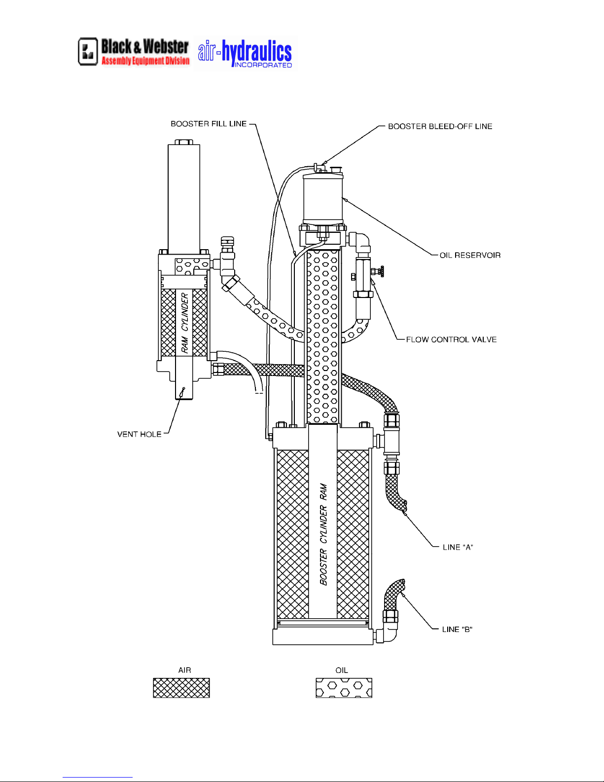
BOOSTER SYSTEM INSTALLATION INSTRUCTIONS
The booster is generally installed in a vertical position but may be installed horizontally. The reservoir
must always be located higher than the top of the booster or the ram cylinder. Securely fasten the booster
to a machine frame that does not move. Install the ram cylinder in a frame sufficient to withstand the
forces that the cylinder produces. Failure to do so will result in damage and potential danger to the
machine operator.
Install incoming air supply (35-110 P.S.I.) through an approved safety lockout valve which is upstream of
an FRL unit. The FRL unit consists of a filter, pressure regulating valve, and an air lubricator connected
in proper order with arrows indicating the direction of air flow. It should be installed in the air line in a
horizontal position as close to the booster system as possible with the pressure gauge visible from the
operating position in front of the system.
The ability to bleed air out of the system is absolutely necessary. Be sure to install bleed caps near the top
of the booster and near the top of the ram cylinder when plumbing the system. When filling the system,
make sure the ram is in the fully retracted position, the booster piston is fully retracted and then fill the
system with the proper oil. Also fill the reservoir so that it is half full and no air bubbles are seen in the
tube from the bottom of the reservoir. After filling, make sure no air is left in the lines and install the and
reinstall the bleed caps.
Turn on air and make sure there are no air leaks. Unscrew filler plug in lubricator and fill with a good
grade of number 10 lubricating oil. Operate system and adjust nut on top of lubricator until an occasional
drop of oil is passed into the air line. Use Mobil 24 or 25 hydraulic oil or the equivalent.
Caution: Incoming air pressure should never exceed 110 psi.