Blue Ice BLUI-150A Manuale utente
ver.201701_01
Installation and User’s Manual
I512A-023
BLUI-150A
BLUI-250A
Freight Claim Procedure (IMPORTANT)
1.
Specifications ........................................................................................... 4
1.1Technical Specification
1.2 Product Dimensions
1.3 Accessories Included in the Machine
1.4 Nameplate Format
2. Installation & Operation Guide ............................................................... 7
2.1
IMPORTANT : Before Installation
2.1.1 Installation Requirements
2.1.2 Location
2.2 Electrical Requirements
2.3 Water Supply & Drain Connections
2.3.1 Water Supply
2.3.2 Water Supply Line
2.3.3 Drainage Line
2.4 Final Check
2.5Test Run
2.6 Operation
2.6.1 Button
2.6.2 Status Light
2.6.3 7-segment
2.7 Operation Cycle
2.8 Safety
2.9 Error Code
3. Maintenance & Cleaning ....................................................................... 16
3.1 Maintenance
3.2 [BLUI-150A] Interior Cleaning & Sanitizing Procedure
3.3 [BLUI-150A] Product Disassembly
3.4 [BLUI-250A] Interior Cleaning & Sanitizing Procedure
3.5 [BLUI-250A] Product Disassembly
3.6 Exterior Cleaning
3.7 Accessories & Parts Cleaning
3.8 How to prepare for long time storage
Table of Contents
23

Freight Claims Procedure(Important)
23
Inspect Promptly
This product has been carefully inspected and packed in accordance with the
carrier’s packing specifications. Responsibility for safe delivery has been
assumed by the carrier. If loss or damage occurs, you as the consignee must file
a claim with the carrier and hold the container for carrier’s inspection.
Visible Loss or Damage
Any external evidence of loss or damage must be fully described and noted on
your freight bill or express receipt and signed by the carrier’s agent.The claim
should be filed on a form available from the carrier.
Concealed Loss or Damage
Concealed loss or damage should be reported to the carrier and vendor within 24
hours after delivery.
After this time the seller is not responsible for any freight damage incurred.
Keep the product as well as all of original packaging material in receiving area for
carrier's inspection.
1. Specifications
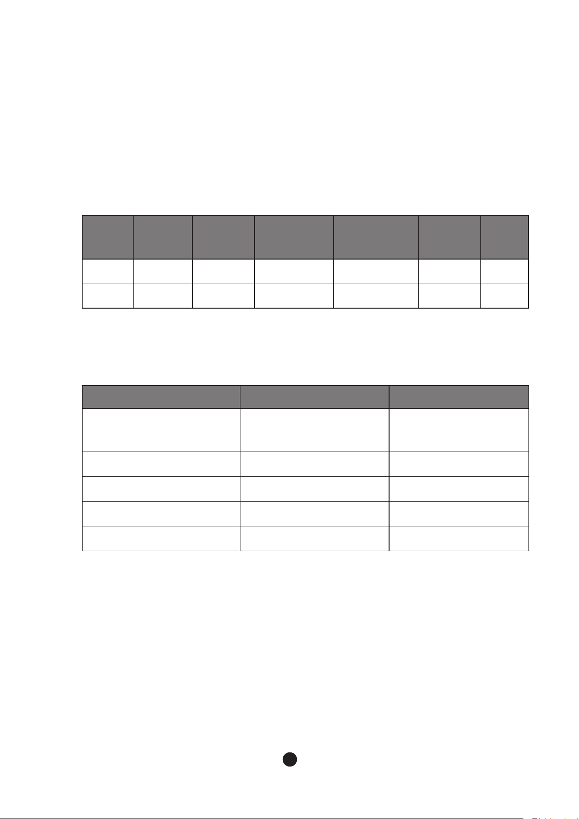
1.1 Technical Specification
Model Total AMPs Condenser
Maximum Fuse/
Circuit Breaker Rating Maximum
Current
Energy
Star
BLUI-150A 7.0A Air Cooling 15A 115V/60Hz/1Ph 7.5A Certified
BLUI-250A 8.3A Air Cooling 15A 115-120V/60Hz/1Ph 9.5A Certified
BLUI-150A BLUI-250A
Design Pressure
HI - 220 psig
LOW - 105 psig
HI - 460 psig
LOW - 210 psig
Refrigerant R-134a (8.46 OZ) R-404A (15.9 OZ)
Compressor 98-132V 28.0LRA 5.6RLA 103-127V 39.7LRA 7.6RLA
Pump 115V 0.50FLA 33.4W 115V 0.93FLA 57.5W
Fan 115V 0.53FLA 59.6W 115V 0.53FLA 59.6W
45
● Electrical Data
● Refrigerant Data
CONTENTS1. Specifications
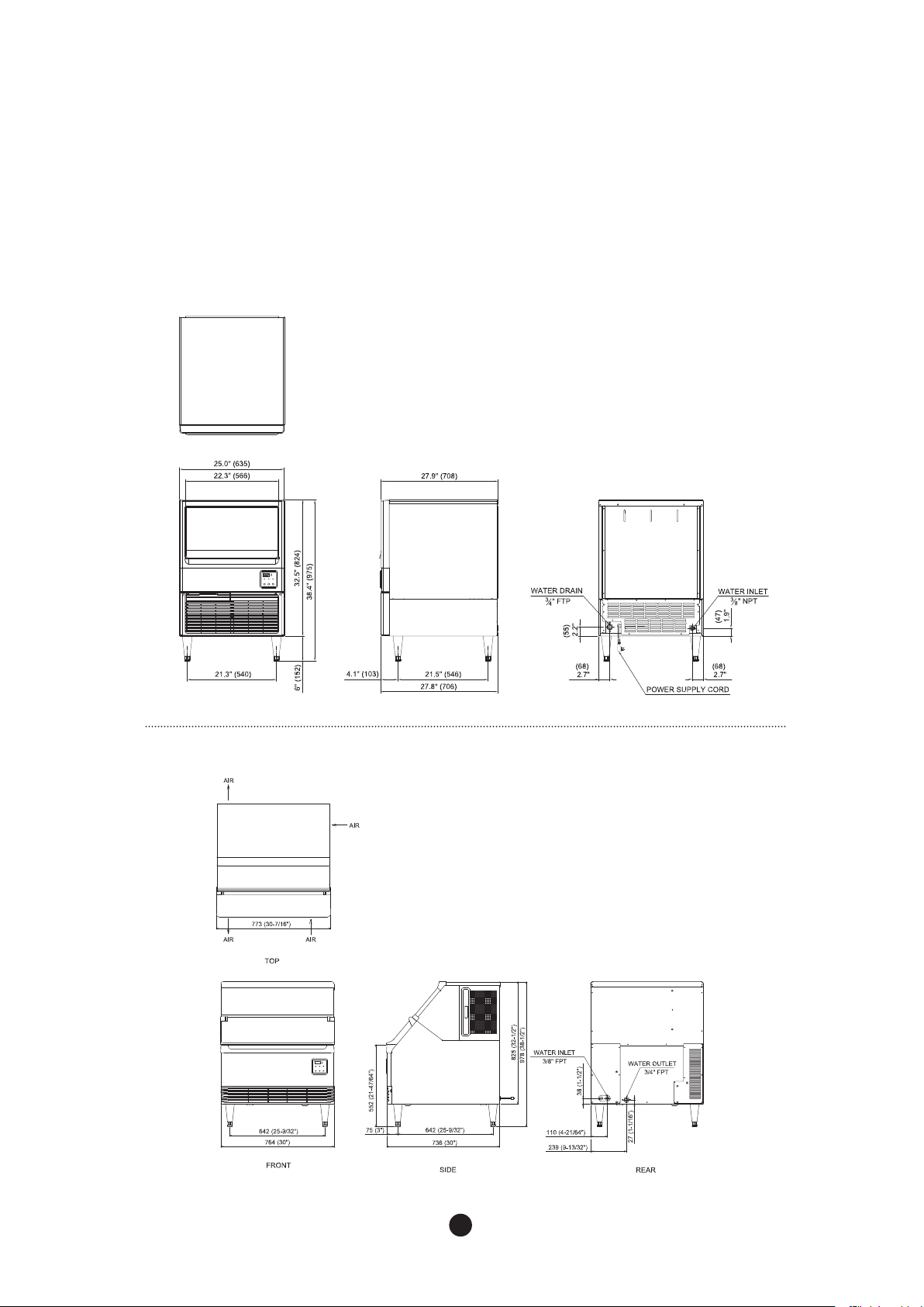
1.2 Product Dimensions
45
● BLUI-150A
● BLUI-250A
67
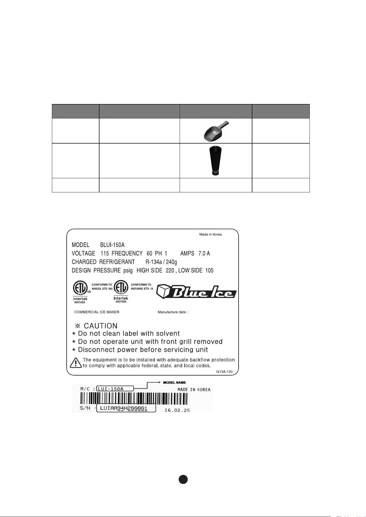
1.3 Accessories Included in the Machine
1.4 Nameplate Format
No Name Picture Quantity
1 Scoop 1
2Legs
6"(150 ~ 176 mm) 4
3 User Manual 1
See the Nameplate for electrical and refrigeration specifications.
This Nameplate is located on the upper part of the Left Side Panel.
We reserve the right to make changes in specifications and design without prior notice.
67
2. Installation & Operation Guide
2.1 IMPORTANT: Before Installation
2.1.1 Installation Requirements
2.1.2 Location
Condition Minimum Maximum
AmbientTemperature
°F 45 100
°C 7 38
WaterTemperature
°F 45 90
°C 7 32
Voltage V 100 130
Water Pressure psig 30
100
WARNING
Our qualified service technicians can only install the product. Likewise, the owner/manager
should not proceed to operate the product until the installer instructs them on its proper use.
Failures to install, operate, and maintain the equipment in accordance with this manual may
adversely affect safety, performance, components’ life, and warranty coverage.The warranty
statement for this product is provided separately from this manual.
In general, warranty covers defects in material or workmanship. It does not cover
maintenance, corrections to installations, or situations when the machine is operated in
circumstances that exceed the limitations printed below.
* Power should be off when installing an ice machine.
*The marking “CAUTION or WARNING - Parts. Do Not Operate Unit With Enclosure
Removed.” (When disassembly for cleaning or similar servicing exposes moving parts
WARNING
Do not put heavy objects over 33 lbs(15kg) on top of the machine. It will need at least 39
inches (1 meter) for service.
89
CONTENTS
-The icemaker is designed for indoor use only.
- Level the icemaker from side to side and front to rear by adjusting the legs.
Location should provide a firm and level foundation for the machine.
-The icemaker should not be located next to ovens, grills, or other high heat producing equipment.
-The legs must be installed before starting the machine.
- After installation, make sure that all the components, fasteners, and screws are all fixed in proper
positions. Check if any of them fell into the storage container.
Please read the following cautions;
-The Icemaker must have the earthwork done.
-The Icemaker must have exchangeable fuse or circuit breaker.
- Decide the appropriate size of the wire based on the length, thickness, and position of the wires.
- Above work has to be done by a qualified electrical engineer.
NOTE : The icemaker requires no clearance at either side. But allow approximately 5” (12cm)
at rear for water supply and drain connections.
2.2 Electrical Requirements
WARNING
- All kinds of power wiring work including power cable connection and earth have to be done
in accordance to the law and regulations of the Country, State, and District.
-The earthwork for icemaker has to be done in accordance to the law and regulations of the
Country, State, and District.
● Voltage
- When operating the icemaker (with maximized electrical load) range of variation in maximum
voltage allowed is +10%/-5% of the rate voltage.
- Specification of the power cord when released from the factory is 6.5’ (2.0m) with NEMA 5-15P Plug.
● Fuse/Circuit Breaker
- Must have the exclusive fuse/circuit breaker for the icemaker.
- As for circuit breaker, US HACR (Heating, Air Conditioning, and Refrigeration) type must be used.
● TOTAL CIRCUIT AMPACITY
- For details about size of cable for power supply, please refer to the “1.1Technical Specification.”

89
In the place where icemaker is installed, it may require an additional processing system to
prevent formation of scale and removing impurities and chlorine for the water quality side.
Please refer to the following instructions for installing water supply line.
- Do not connect hot water system to the icemaker.
- Appropriate water pressure is 30 ~ 100 psig.
- Install shut-off valve to the water supply line.
- Insulate the water supply line to prevent condensation.
To prevent backflow of icemaker and storage container, please refer to the following instructions
for installing drainage line.
- For the smooth drainage, gradient of 1 inch for every 5’ (2.5cm per meter) is needed.
- Do not install any trap.
- Do not connect drainage pipe directly into the sewage pipe.
-There must be minimum 2’’ of air gap vertically between end of drainage pipe and the
drain hole.
- Must install vent.
2.3 Water Supply & Drain Connections
2.3.1 Water Supply
2.3.2 Water Supply Line
2.3.3 Drainage Line
WARNING
- Installation of water supply and pipe system has to be done in accordance to the law and
regulation of the Country, State, and District.
-The icemaker is to be installed with adequate backflow protection to comply with applicable
federal, state, and local codes.
- Water pipe work has to be done by qualified service technicians.
10 11
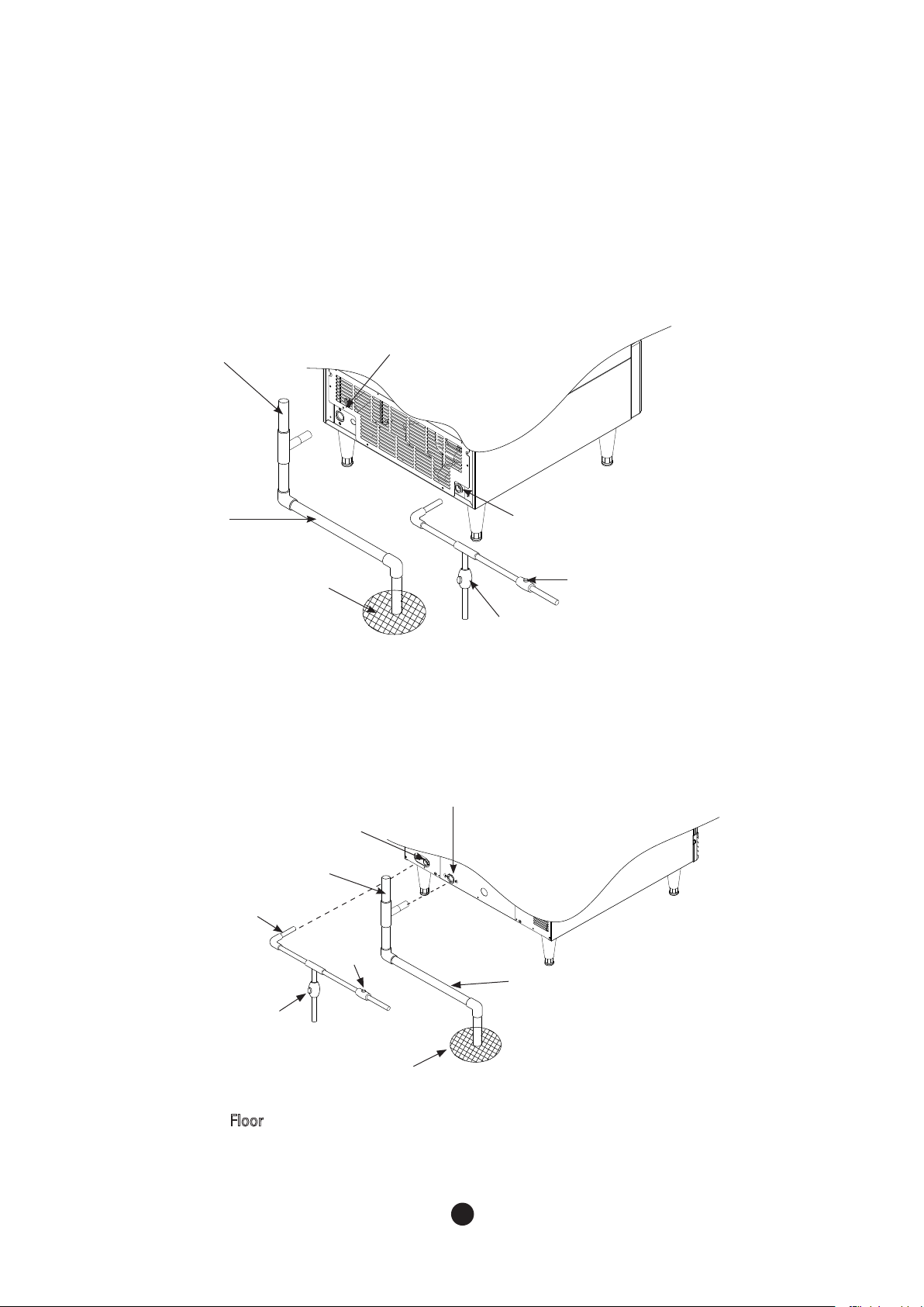
● BLUI-150A
Floor
* Leave a 2”(5 cm) vertical air gap between the end of each pipe and the drain.
Vent tube
Minimum 3 ⁄4:”
ID Hard pipe
Shut- Off
Valve
Floor
Water supply
inlet - 3/8”FPT
Drain Valve
Drain Outlet
- 3 ⁄ 4” FPT
Minimum 1/4”
ID copper pipe
Shut- Off
Valve
Drain Outlet
- 3 ⁄ 4” FPT
Minimum 1/ 4”
ID copper pipe
Water supply
inlet - 3/ 8”FPT
Vent tube
Drain Valve
● BLUI-250A
Minimum 3/ 4
ID Hard pipe
Floor
Questo manuale è adatto per i seguenti modelli
1
Indice


