
Blueview BV5000 Manuale di istruzioni

www.blueview.com
BV5000 User Handbook
Part Number: 202882-01
Revision: A
Updated: April 2010
©BlueView Technologies, Inc. All rights reserved.
All product names are trademarks of their respective companies.

© BlueView Technologies Corp BlueView BV5000 User Handbook
2
BlueView Technologies has made every effort to ensure the
accuracy and completeness of this document; however, because
ongoing development efforts are made to continually improve the
capabilities of our products, we cannot guarantee the accuracy of
the contents of this document. We disclaim liability for errors,
omissions, or future changes herein.
The accompanying Software and Documentation are proprietary
products owned by BlueView Technologies, Inc., and protected
under U.S. and international copyright law. Except as authorized
under this License Agreement, the Software may be used only on
computers owned, leased, or otherwise controlled by you. You may
not reverse assemble, reverse compile, or otherwise translate
ProScan.
Copyright © 2003-2010 BlueView Technologies Corp. All rights
reserved. No part of this publication may be copied, reproduced, or
translated, without the prior written consent of BlueView
Technologies. No part of this publication may be stored or
transmitted in any electronic form without the prior consent of
BlueView Technologies. Any unauthorized use is a violation of
copyright laws. ProScan® is a registered trademark of BlueView
Technologies Corp.

© BlueView Technologies Corp BlueView BV5000 User Handbook
3
Table of Content
Chapter 1 Introduction................................................................5
System Contents......................................................................................5
System Overview .....................................................................................6
Typical 3D Point Cloud Collection Overview...................................................7
Chapter 2 Software Installation...............................................8
ProScan Installation..................................................................................8
Meshlab Installation..................................................................................8
Leica Cyclone...........................................................................................9
Chapter 3 System Assembly and Testing ............................... 11
Assembling the Hardware ........................................................................ 11
Connect Components .............................................................................. 12
Installing the Pan and Tilt Drivers ............................................................. 13
Setup PC IP Address ............................................................................... 16
Connect to the BV5000............................................................................ 17
Installation of the Pan & Tilt Unit .............................................................. 18
Chapter 4 ProScan Software Basics ........................................... 20
Typical ProScan Screenshot...................................................................... 20
Image Display........................................................................................ 21
Toolbar ................................................................................................. 22
Toolbar ................................................................................................. 23
Range Controls....................................................................................... 24
Range and Bearing ................................................................................. 24
Playback Controls ................................................................................... 25
Settings/Sonar Control............................................................................ 26
Manual Image Calibration ........................................................................ 27
Pan and Tilt Controls............................................................................... 28
Screen Information................................................................................. 29
Scan Setup............................................................................................ 30
Chapter 5 Recording and Reprocessing Data ............................. 33
Configure Recording................................................................................ 33
Scan Intensity Files (.son) ....................................................................... 34
3D Point Cloud Files (.xyz & .off) .............................................................. 34
Sonar Settings File (.txt) ......................................................................... 35

© BlueView Technologies Corp BlueView BV5000 User Handbook
4
Reviewing Data...................................................................................... 35
Reprocessing Saved Data ........................................................................ 35
Chapter 6 System Troubleshooting........................................37
Sonar + Pan & Tilt Connection Issues........................................................ 37
Pan & Tilt Connection Issues .................................................................... 37
Sonar Head Connection Issues ................................................................. 40
Image and Scan Problems ....................................................................... 43
BlueView Customer Support..................................................................... 45
Chapter 7 System Specifications............................................46
Appendix A Typical Installation Configurations ..................... 47
Typical Tripod and Fixed Configurations ..................................................... 47
Typical ROV Configuration........................................................................ 48
Appendix B System and Cable Diagrams................................ 49
Sonar / Pan and Tilt Cable ....................................................................... 49
Pan and Tilt Outline Drawing .................................................................... 50
MB2250-45 Outline Drawing..................................................................... 51
MB1350-45 Outline Drawing..................................................................... 52

© BlueView Technologies Corp BlueView BV5000 User Handbook
5
Chapter 1 Introduction
The BV5000 is a 3D mechanical scanning system that combines the data quality
of BlueView’s high-frequency microbathymetry sonar with the ease of use of
traditional 2D scanning sonar. This manual covers setup, installation, operation,
and technical specifications of BlueView’s 3D mechanical scanning sonar system.
When ordered, the BV5000 ships with either a 1.35 or 2.25 MHz sonar head, which
are both covered in this manual. For specific details on individual sonar head
specifications, see the specifications tables listed in the specification section of this
manual.
System Contents
Verify that your delivered system includes the following components:
•Sonar Head
•Pan & Tilt Unit
•Sonar, Pan & Tilt Junction Box
•Shipping Case, BV-5000
•Hex Driver
•Cable, Cat5, Ethernet
•Cable, USB
•Cable, Power
•Proscan CD w/ Meshlab
•USB Driver CD
•Test Cable, 15 ft.
•BV5000 User’s Handbook

© BlueView Technologies Corp BlueView BV5000 User Handbook
6
System Overview
Through mechanical rotation of the sonar head, the BV5000 is capable of
producing 3D point clouds from a stationary location. Some of the more common
delivery methods (tripods and ROVs) are shown in the figures below. Notice the
volumetric scan zones around the sonar. With each scan, a large amount of high
resolution 3D data is collected.
The system works by mechanically scanning a thin vertical sonar slice around
the selected area as shown in the figure below. At each direction, a profile of the
surface is taken and added to the other direction profiles to create a final 3D point
cloud similar to the one shown below.

© BlueView Technologies Corp BlueView BV5000 User Handbook
7
Typical 3D Point Cloud Collection Overview
This section provides a quick overview of a typical collection process.
Deploy the System
Position the BV5000 into the desired scan location. For tripod type systems,
verify that sonar is upright by viewing proper movement of the bottom imagery as
the sonar is tilted up and down using the pan and tilt controls.
Set Sound Speed
Open the File/Settings/Sonar Controls menu and enter the measured or
estimated sound speed of water for the scan location.
Image Calibration
To calibrate the image, first make sure that the sonar is thermally stabilized to
the ambient water temperature, then use the pan and tilt controls to point the
sonar so that its beam is grazing a relatively flat surface as described later in this
manual. Press the auto-calibration icon, then visually assess the calibration.
Enter Scan Parameters and Start Scan
Select the “Scan” button located under the pan and tilt controls to bring up the
“Scan Controls” window. Setup the desired scan process and enter any position
and orientation data available (not required). Press “Start Scan” to begin the scan
process. Depending on how the scan is configured, scans can take between 1-18
minutes to complete.
Monitor Scan Process
ProScan visually shows the intensity map (copper) and the selected point cloud
surfaces (blue) the current ping position. ProScan also brings up a status window
for the current scan. No 3D imagery is available until the scan is complete.
Point Cloud Viewing and Measurements
Use a point cloud viewer to spin the 3D point cloud around and view from
different angles. Take point to point measurements to make accurate distance
and size measurements. Once such viewer, MeshLab, is supplied with your
BV5000 system. All measurements are in meters.
Advanced Data using Cyclone
If required, use a third party software such as Cyclone by Lieca Geosystems to
perform advanced cleaning, registration, and modeling functions on the data.

© BlueView Technologies Corp BlueView BV5000 User Handbook
8
Chapter 2 Software Installation
Your mechanical scanning system includes a disk containing BlueView’s ProScan
sonar software, as well as Meshlab, a point cloud viewing program. For proper
system testing and operation, ProScan and Meshlab should both be installed on
your collection PC. Cyclone by Leica Geosystems is sold separately.
ProScan Installation
To install ProScan, insert the ProScan CD into your computer’s CD-ROM drive
and follow the instructions to complete the installation. You may also launch the
installation by double clicking on “setup.exe” in the CD’s root directory.
When ProScan starts, if a personal firewall is enabled, a warning message may
pop up saying that ProScan is attempting to connect to the network. BlueView
recommends selecting the option that will always allow ProScan to access the
network (which it needs to do to communicate with sonar).
ProScan Software System Requirements
ProScan requires a system that meets or exceeds the following requirements for
optimum performance.
•Windows 2000, XP, or Vista operating system
•Dual-Core 1.8 GHz or faster processor
•1GB or more of RAM
•2GB or more of free disk space
•CD-ROM drive for installation
•1 Ethernet Port and 1 USB Port
Meshlab Installation
The installer for Meshlab, a 3D point cloud viewer and measurement package, is
included on the ProScan CD. To install Meshlab, just double click the
Meshlab_v121.exe file. Follow the instructions and accept the default options to
complete the installation. Refer to Help menu in Meshlab for operational
information.

© BlueView Technologies Corp BlueView BV5000 User Handbook
9
Leica Cyclone
Note: The Cyclone software package is sold separately from the base BV5000
package. Contact BlueView sales for more information on obtaining trial and
permanent licenses for the Cyclone software package.
Cyclone by Leica Geosystems is a point cloud manipulation software package
that provides advanced operations such as cleaning, registering scans from
several locations, and modeling engineering objects for output to standard cad
products. BlueView sells the Cyclone package as an optional software accessory
for those requiring this type of package.
Software Options
Cyclone is originally installed with only its Viewer functionality enabled. By
purchasing additional licenses, some of the more advanced features can be
activated for use. The table below outlines some of the different features
associated with the different license options available.
Feature Cyclone
Viewer Cyclone
Register Cyclone
Model
Point Cloud Viewing X X X
Measurement X X
Data Cleaning X X
Insert Reference Points X X
Insert Reference Surface X X
Global & Local Registration X
Advanced Modeling (from catalogs) X
Point Cloud Export X X
CAD Export X X
© BlueView Technologies Corp BlueView BV5000 User Handbook
10
Cyclone Installation Instructions
1. The Cyclone software installation files can either be downloaded directly
from the Lieca Geosystems website or found on CDs that come you’re your
purchased Cyclone software suite.
2. Install Cyclone and take note of the installation directory.
3. If you either requested a trial license, or purchased a permanent license, a
license file should have been provided to you as a file named “license.dat.”
4. Copy this file into the installation directory.
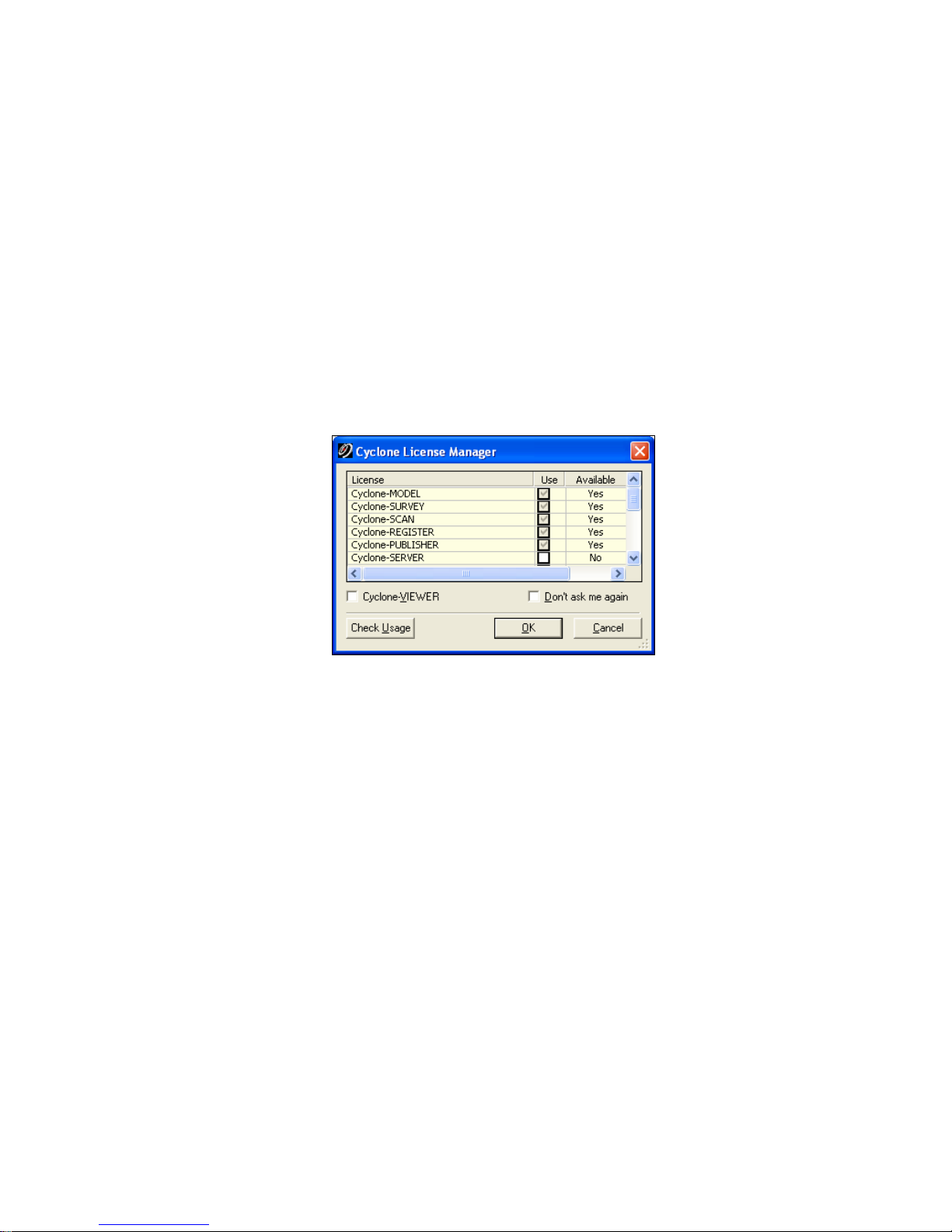
5. Launch Cyclone. A dialog should appear outlining the available licenses and
expiration dates.
6. If the available licenses do not appear in the dialog, the individual licenses
may need to be activated in the “License Manager” from the Help dropdown
in the Navigator window.
Indice


